ALLEN + ROTH and logo design are trademarks or
registered trademarks of LF, LLC. All rights reserved.
Español p. 29
ATTACH YOUR RECEIPT HERE
SG24392
Serial Number__________________
Purchase Date__________________
Thank you for purchasing this ALLEN + ROTH product.
Questions, problems or missing parts?
Before returning contact us on:
, 8 a.m. - 8 p.m., EST, Monday - Sunday or
866-439-9800
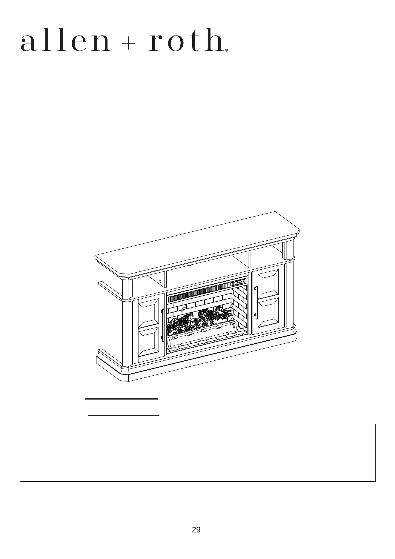
ITEM #5691735
MODEL #1010MFP-58-26-501
58-IN ELECTRIC
FIREPLACE
1

TABLE OF CONTENTS
Package Contents ............................................................................................................................... 3
Hardware Contents.............................................................................................................................. 4
Safety Information ............................................................................................................................... 4
Preparation .......................................................................................................................................... 8
Assembly Instructions.......................................................................................................................... 8
Maximum Recommended Weight Loads ........................................................................................... 22
Operating Instructions ....................................................................................................................... 23
Care And Maintenance ...................................................................................................................... 25
Troubleshooting ................................................................................................................................. 26
One-Year Limited Warranty ............................................................................................................... 27
Replacement Parts List ..................................................................................................................... 28
2
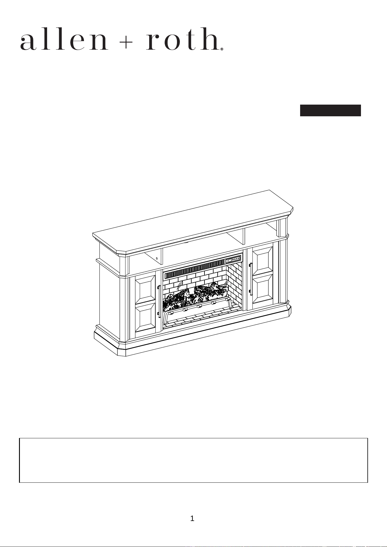
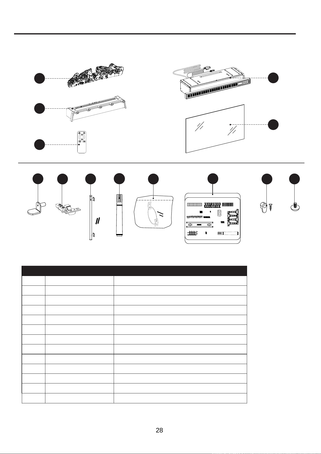
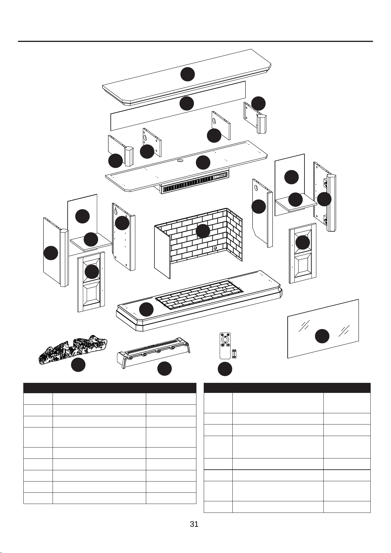
PACKAGE CONTENTS
A
Top
1
B
Corner Panel
2
C
Partition Panel
2
E
1
F
Left Middle Wall
1
G
Right Middle Wall
M 1
N 1
O
Fireplace Grate
1
K
Remote Control
(with Battery)
1
L
Fireplace Glass Front
2
H
Outer Wall
I
J
Shelf
2
2
Door
2
R
Center Back Panel
1
Q
Back Panel
Base
1
Fireplace Brick Wall
Fire Log
1
QUANTITYDESCRIPTIONPART
QUANTITYDESCRIPTIONPART
A
K
B
BB
C
C
D
J
Q
O
N
M
R
L
L
H
G
I
E
F
H
G
I
Center Shelf And
Heater
1
D
3
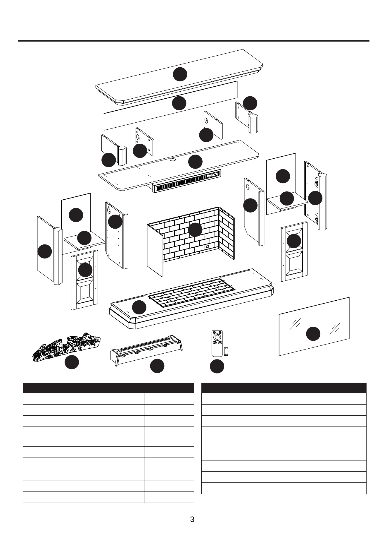
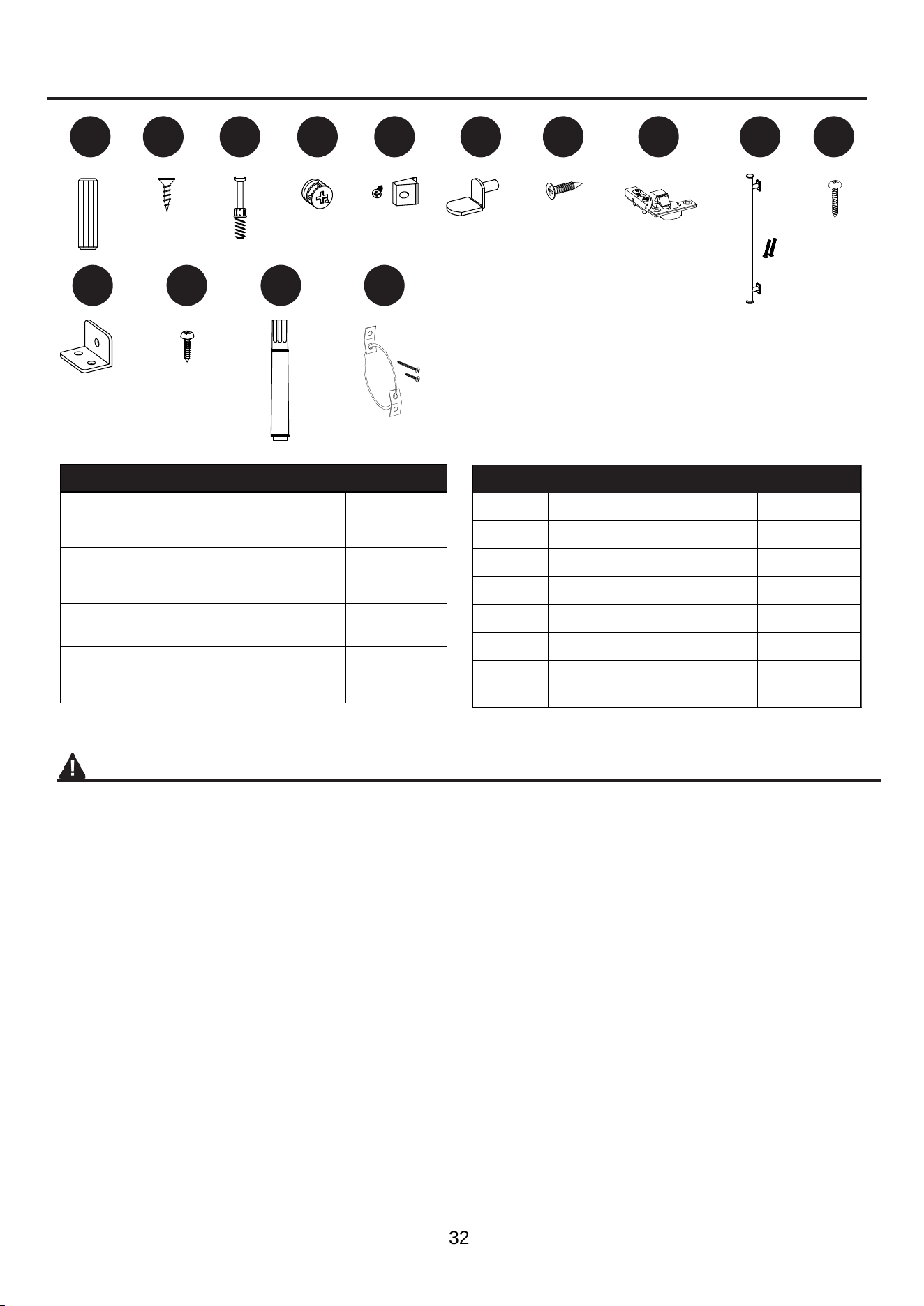
HARDWARE CONTENTS (NOT SHOWN ACTUAL SIZE)
AA BB II JJCC DD EE FF GG HH
KK LL MM NN
QUANTITYDESCRIPTIONPART QUANTITYDESCRIPTIONPART
SAFETY INFORMATION
Please read and understand this entire manual before
attempting to assemble, operate or install the product.
This equipment has been tested and found to comply
with the limits for Class B digital devices, pursuant to
Part 15 of the FCC rules. These limits are designed
to provide reasonable protection against harmful
interference in a residential installation. The equipment
generates, uses and can radiate radio frequency
energy and, if not installed and used in accordance
with the instructions, may cause harmful interference
to radio or television reception, which can be
determined by turning the equipment off and on. The
user is encouraged to try and correct the interference
by one or more of the following measures:
• Reorient or relocate the receiving antenna.
•
Increase the separation between the equipment and
the receiver.
• Connect the equipment into an outlet on a
circuit different from that to which the receiver is
connected.
•
Consult the dealer or an experienced radio/TV
technician for help.
This device complies with Part 15 of the FCC rules.
Operation is subject to the following two conditions:
1. This device may not cause harmful interference,
and
2. This device must accept any interference received,
including interference that may cause undesired
operation.
KEEP THESE INSTRUCTIONS FOR FUTURE REFERENCE.
AA
Wooden Dowel
32
BB
Short Screw
2
CC
Connecting Rod
32
DD
Locknut
32
EE
Back panel mounting
hardware with screw
14
FF
Shelf Pin
8
GG
Hinge Screw
8
HH
Hinge
4
II
Door Pull
2
JJ
KK
Long Screw
2
LL
L-Bracket
2
MM
Screw
6
Touch-up Pen
1
NN
Tip Restraint Hardware
2
4
SAFETY INFORMATION (CONTINUED)
Modifications not approved by the party responsible
for compliance could void user’s authority to operate
the equipment.
This Class B digital apparatus complies with Canadian
ICES-003.
IMPORTANT INSTRUCTIONS
When using electrical appliances, basic precautions
should always be followed to reduce the risk of fire,
electric shock and injury to persons, including the
following:
DANGER
• To reduce the risk of electrical shock, ensure the
product is stable and avoid tipping.
• Read all instructions before installing or using this
heater.
• If the information in this manual is not followed
exactly, an electric shock or fire may result causing
property damage, personal injury or loss of life.
• ALWAYS unplug this appliance/furnishing from the
electrical outlet before cleaning or servicing.
• This product is intended to fit most plasma and
LCD televisions (up to 72 inches and weighing a
maximum of 95 pounds). Using this item with loads
heavier than the stated maximum can result in
tipping and/or instability, which can result in injury or
even death.
WARNING
• This appliance is hot when in use. To avoid burns,
DO NOT let bare skin touch hot surfaces. Keep
combustible material, such as furniture, pillows,
bedding, papers, clothes and curtains at least 3 feet
from this appliance and keep them away from the
sides and rear.
• Extreme caution is necessary when any heater
is used by or near children or individuals with
disabilities and whenever the fireplace is left
operating and unattended.
• DO NOT run cord under carpeting. DO NOT cover
cord with throw rugs, runners, or similar coverings.
• DO NOT route cord under furniture or appliances.
Arrange cord away from traffic areas and where it
will not be tripped over.
• DO NOT insert or allow foreign objects to enter any
ventilation or exhaust opening as this may cause
an electric shock or fire or damage the appliance.
• This appliance has hot and arcing or sparking parts
inside. DO NOT use it in areas where gasoline,
paint or ammable vapors or liquids are used or
stored. This fireplace should not be used as a
drying rack for clothing. Christmas stockings or
decorations should not be hung in the area of it.
• Use this appliance only as described in the manual.
Any other use is NOT recommended by the
manufacturer and may cause fire, electric shock or
injury to persons.
• Reduce the risk of burns, fire, electrical shock, or
injury to persons:
• Unplug from outlet before putting on or taking off
parts.
• Close supervision is necessary when this furnishing
is used by, or near children, invalids, or disabled
persons.
• Use this furnishing only for its intended use
as described in these instructions. DO NOT
use attachments not recommended by the
manufacturer.
• Keep the cord away from heated surfaces.
• Never operate the furnishing with the air openings
blocked. Keep the air openings free of lint, hair, and
other debris.
• Never drop or insert any object into any opening.
• DO NOT operate where aerosol (spray) products
are being used or where oxygen is being
administered.
• To disconnect, turn all controls to the off position,
then remove plug from outlet.
• Each surface intended to support a load shall have
a corresponding statement in the use instructions
specifying the maximum intended load for that
surface in pounds (kilograms).
• Risk of electric shock-connect this furnishing to
a properly grounded outlet only. See Grounding
Instructions.
5

SAFETY INFORMATION (CONTINUED)
• To avoid electric shock, fire, or injury, review the
assembly instruction to confirm that the appropriate
critical components and accessories are being used
with the furnishing.
• Death or serious injury may occur when children
climb on audio and/or video equipment furniture. A
remote control or toys placed on the furnishing may
encourage a child to climb on the furnishing and as
a result the furnishing may tip over on to the child.
• Relocating audio and/or video equipment to
furniture not specifically designed to support audio
and/or video equipment may result in death or
serious injury due to the furnishing collapsing or
overturning onto a child.
CAUTION
• DO NOT operate any heater with a damaged cord
or plug or after the heater malfunctions. DO NOT
operate any heater if it has been dropped or
damaged in any manner. Disconnect power at
service panel and have heater inspected by a
reputable electrician before reusing.
• Any repairs to this fireplace should be carried out by
a qualified service person.
• Under no circumstances should this fireplace be
modified. Parts having to be removed for servicing
must be replaced prior to operating this fireplace
again.
• Household use only.
• DO NOT use outdoors.
• “WARNING – Death or serious injury may occur
when children climb on audio and/or video
equipment furniture. A remote control or toys placed
on the furnishing may encourage a child to climb on
the furnishing and as a result the furnishing may tip
over on to the child”.
• “WARNING – Relocating audio and/or video
equipment to furniture not specifically designed to
support audio and/or video equipment may result
in death or serious injury due to the furnishing
collapsing or overturning onto a child”.
• This heater is not intended for use in bathrooms,
laundry areas and similar indoor locations. NEVER
place heater where it may fall into a bathtub or other
water container.
• To disconnect this appliance, turn controls to the
OFF position, then remove plug from outlet.
• ONLY connect to properly grounded outlets.
• This appliance, when installed, must be electrically
grounded in accordance with local codes, with the
current CSA C22.1 Canadian Electrical Code or
follow U.S.A. Installations, follow local codes and
the National Electrical Code, ANSI/NFPA N0.70.
• To prevent a possible fire, DO NOT block air intakes
or exhaust in any manner. DO NOT use on soft
surfaces, like a bed, where opening may become
blocked.
• The heaters MUST NOT be located immediately
below a socket-outlet.
• ALWAYS plug heaters directly into a wall outlet /
receptacle. NEVER use with an extension cord,
re-loadable power tap (outlet / power strip) or a
smart outlet.
• DO NOT slide insert on top of wood to avoid
scratching wood surface.
• DO NOT place any object on top of the insert or
block the air intakes / vents as this can cause the
unit to overheat and could cause a fire.
6
SAFETY INFORMATION (CONTINUED)
Electrical Connection
• A 15-Amp, 120-volt, 60 Hz circuit with a properly
grounded outlet is required. Preferably, the
fireplace will be on a dedicated circuit as other
appliances on the same circuit may cause the circuit
breaker to trip or the fuse to blow when the heater
is in operation. The unit comes standard with 6-ft.
three-wire cord, exiting from the rear of the
fireplace. DO NOT exceed the current rating of the
current tap.
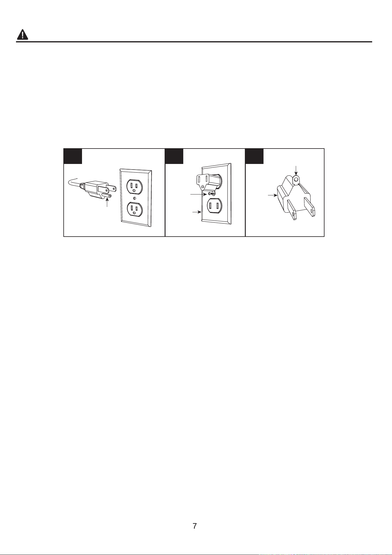
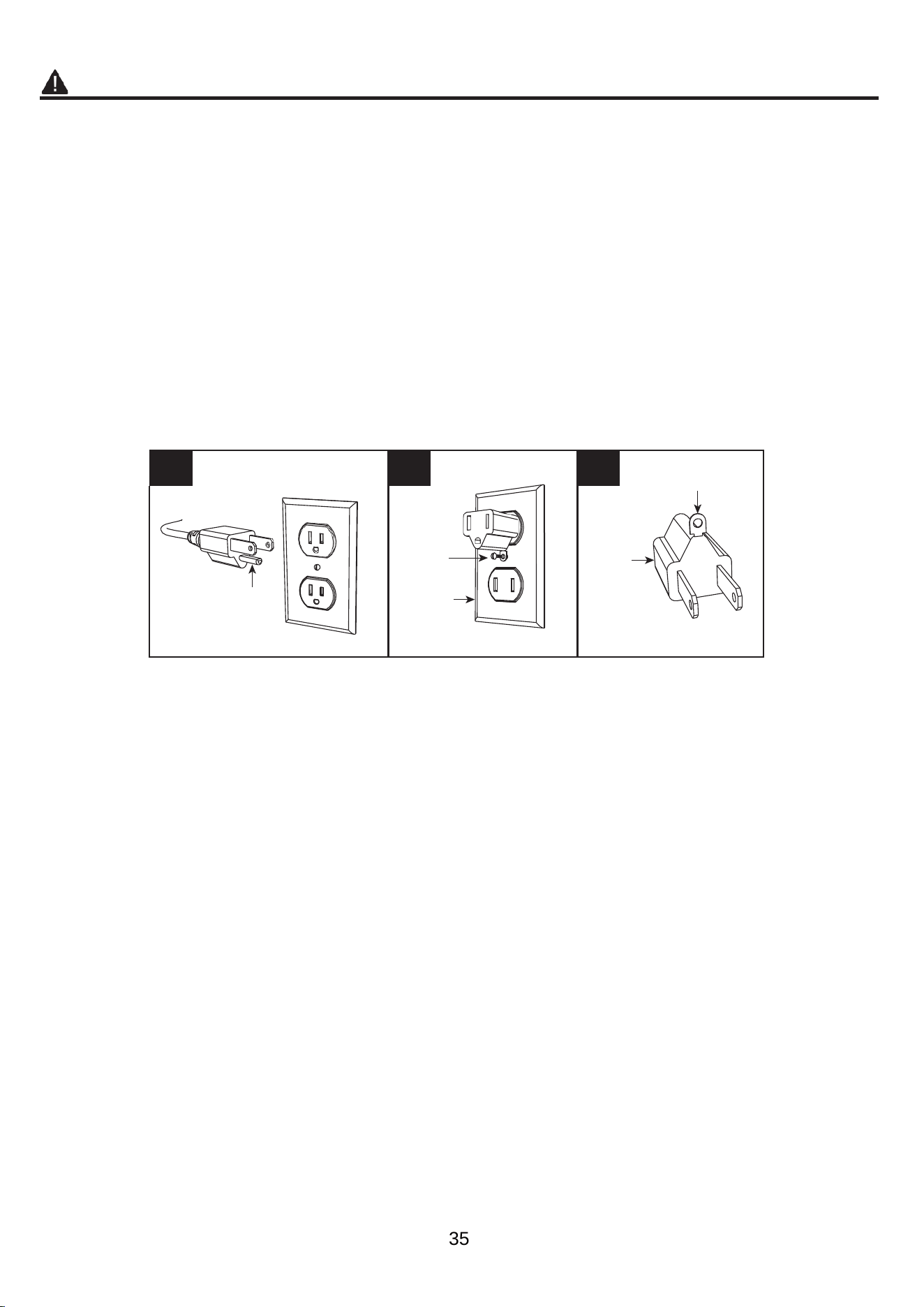
Grounding Instructions
• This heater is for use on 120-volt. The cord has a
plug as shown below. See illustration or grounding
instruction. An adapter as shown at C is available
for connecting three-blade grounding type plugs
to two-slot receptacles. The green grounding plug
extending from the adapter must be connected to
a permanent ground such as a properly grounded
outlet box. The adapter should not be used if a
three-slot grounded receptacle is available.
A B C
Grounding Pin
Grounding Means
Metal
Screw
Cover of
Grounding
Box
Adapter
SAVE THESE INSTRUCTIONS
7
PREPARATION
Before beginning assembly of product, make sure
all parts are present. Compare parts with package
contents list and hardware contents list. If any part is
missing or damaged, do not attempt to assemble the
product.
Estimated Assembly Time
: 40 minutes
Tools Required for Assembly (not
included): Phillips screwdriver
ASSEMBLY INSTRUCTIONS
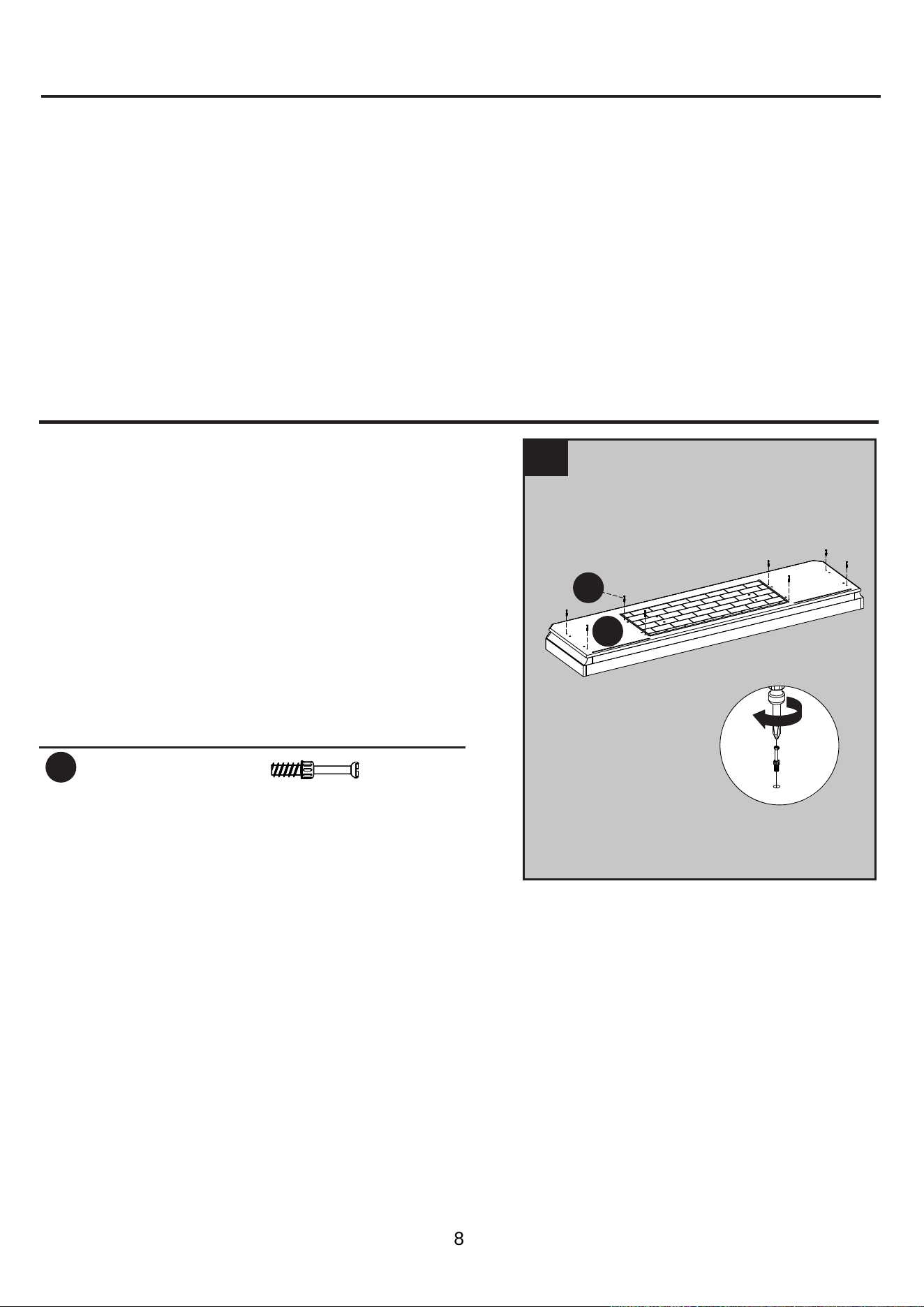
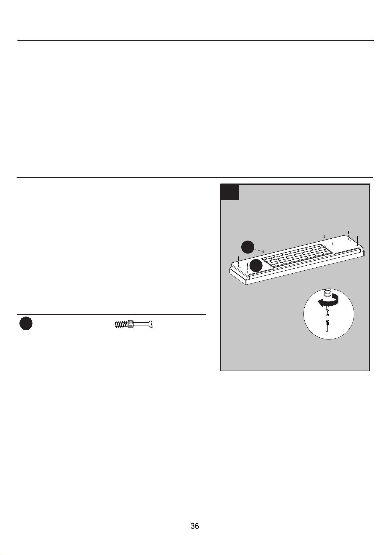
1.
Hardware Used
CC
Connecting Rod
x 8
1
CC
Q
Screw eight connecting rods (CC) into the holes
on the top of the base (Q).
8
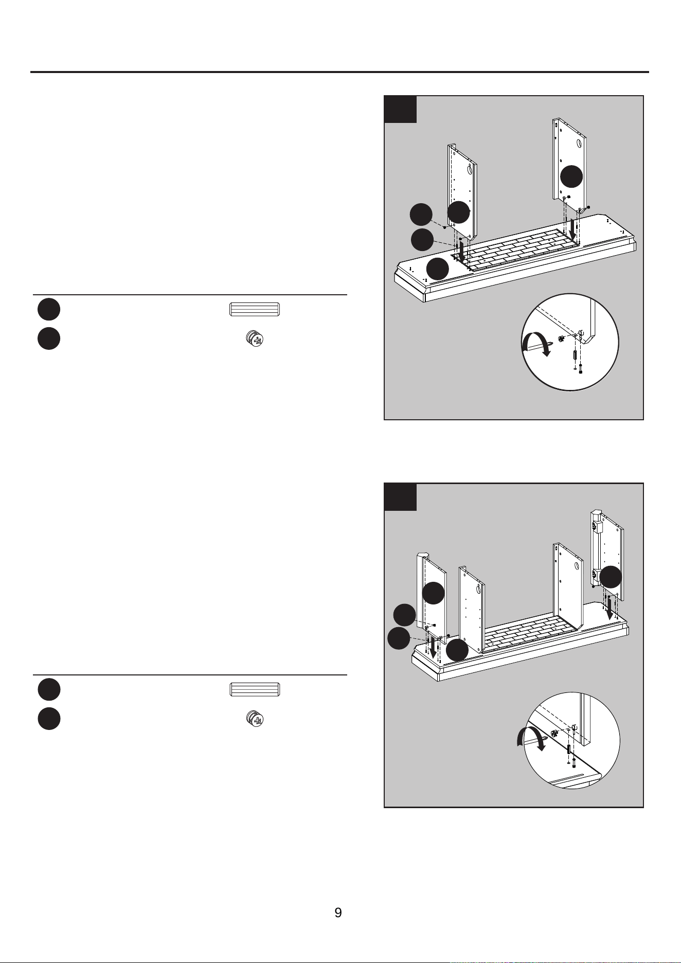
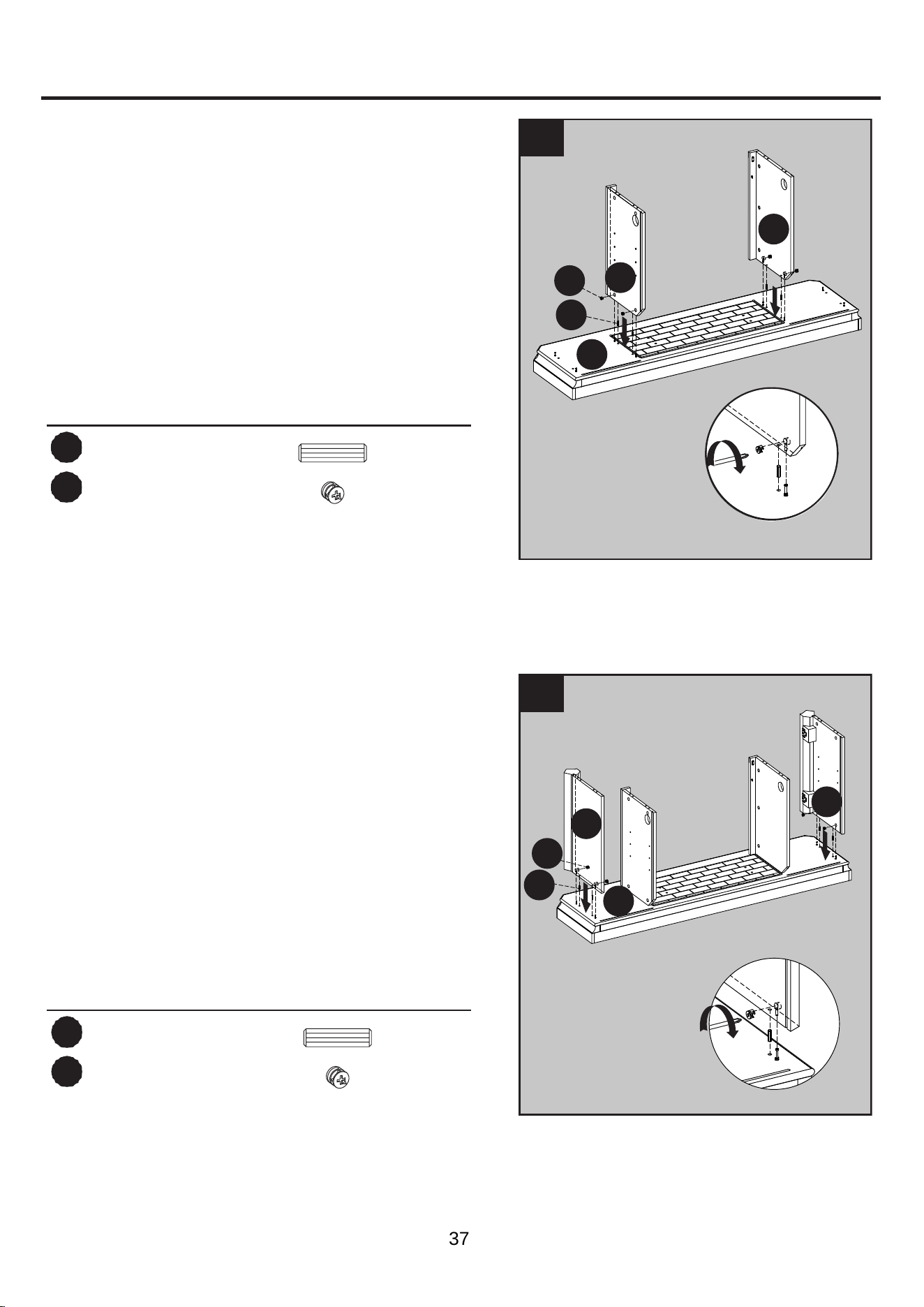
2.
As shown in the diagram, insert four wooden
dowels (AA) into the holes of base
(Q).
four locknuts
(DD) by
Phillips screwdriver.
Hardware Used
AA
Wooden Dowel
x 4
DD
Locknut
x 4
ASSEMBLY INSTRUCTIONS (CONTINUED)
2
3
1
1
1
AA
DD
Q
F
E
2
3. Insert two wooden dowels (AA) into the outer
holes to the right of the base (Q).
Attach the outer wall (G), secure with screwing
two locknuts (DD) by Phillips screwdriver.
Repeat for the remaining outer wall (G).
Attach the left middle wall (E) and right middle
wall (F), secure with screwing
Hardware Used
AA
Wooden Dowel
x 4
DD
Locknut
x 4
2
AA
DD
Q
G
G
1
1
9
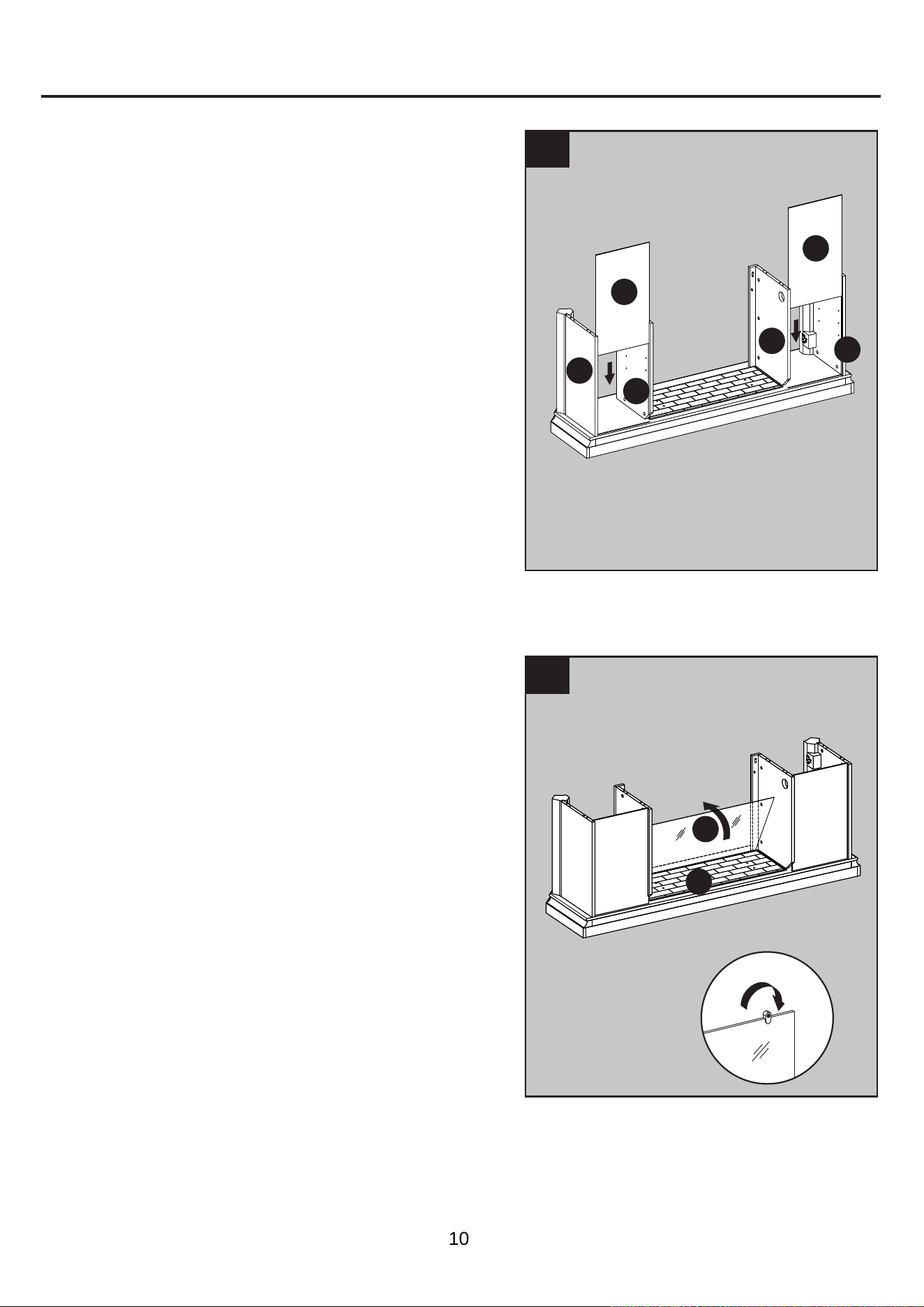
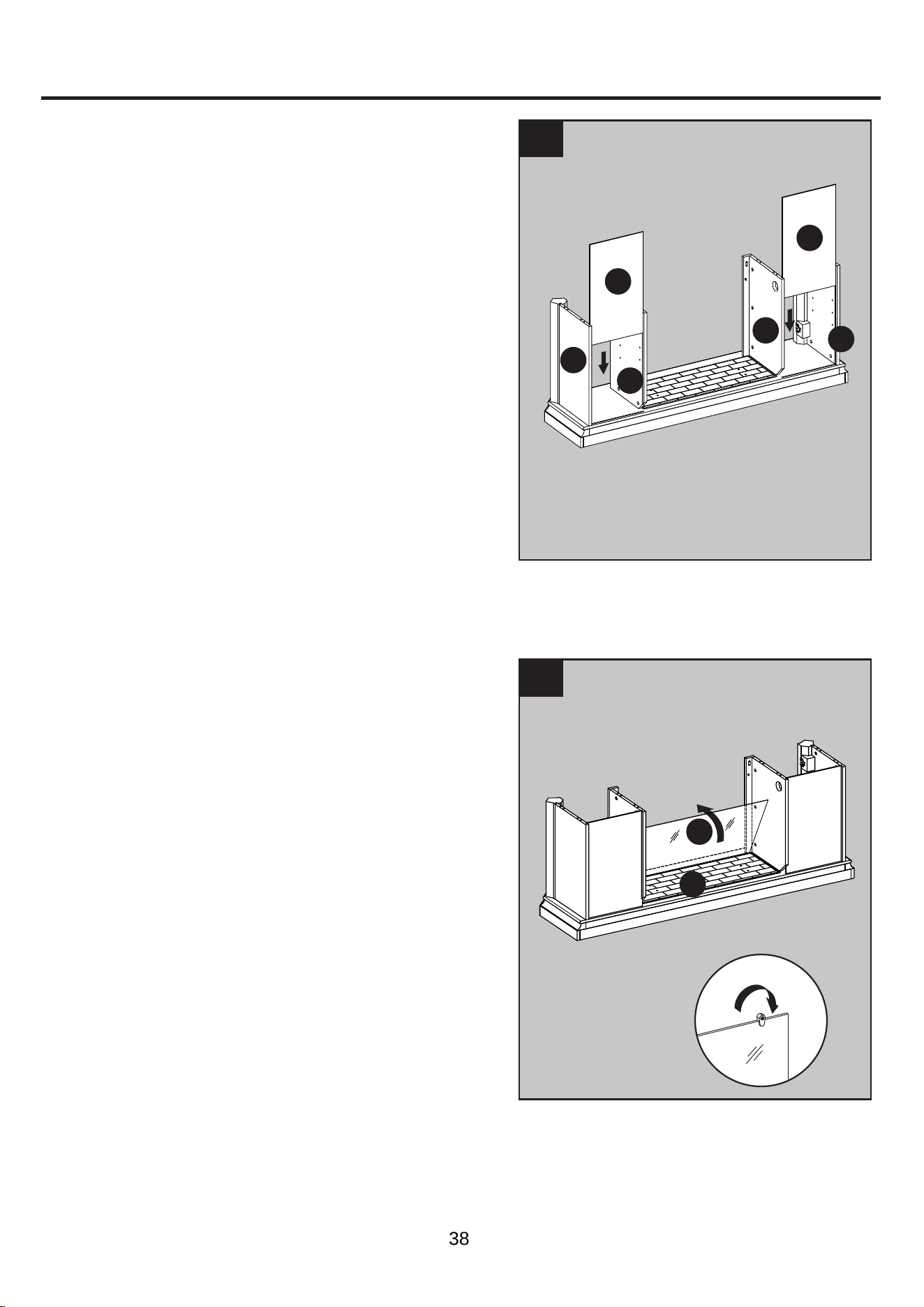
4. As shown in the diagram, insert the back panels
(L) along the grooves of the middle walls (E, F)
and outer walls (G).
ASSEMBLY INSTRUCTIONS (CONTINUED)
4
5
L
L
G
G
F
E
2
1
R
Q
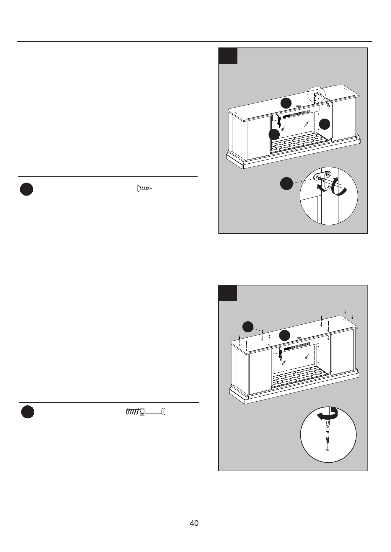
5.
Attach the
fireplace
glass front (R), lowering
it into the front groove
on base
(Q). Secure
the glass by
turning the pre-assembled
plastic knobs.
10
ASSEMBLY INSTRUCTIONS (CONTINUED)
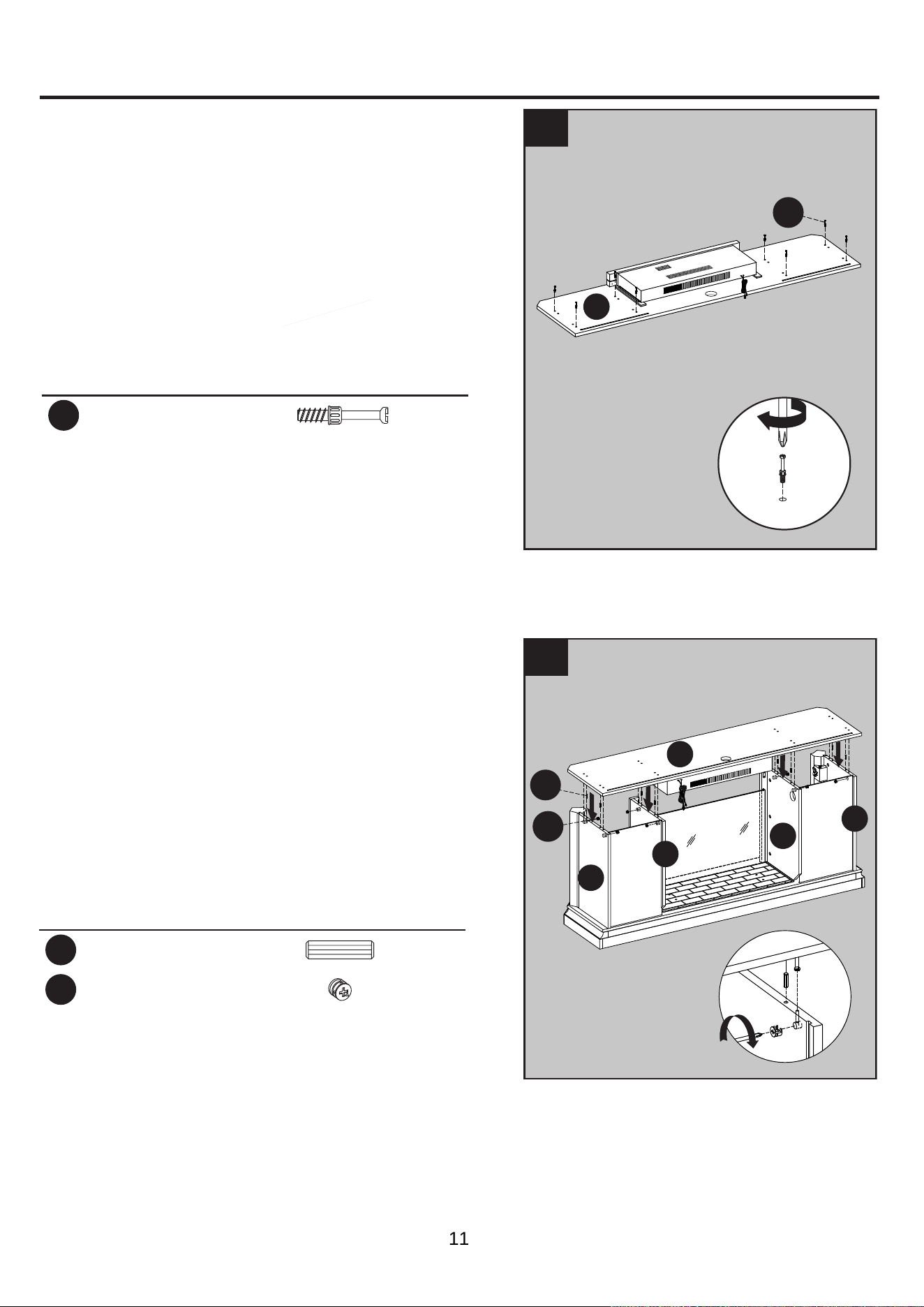
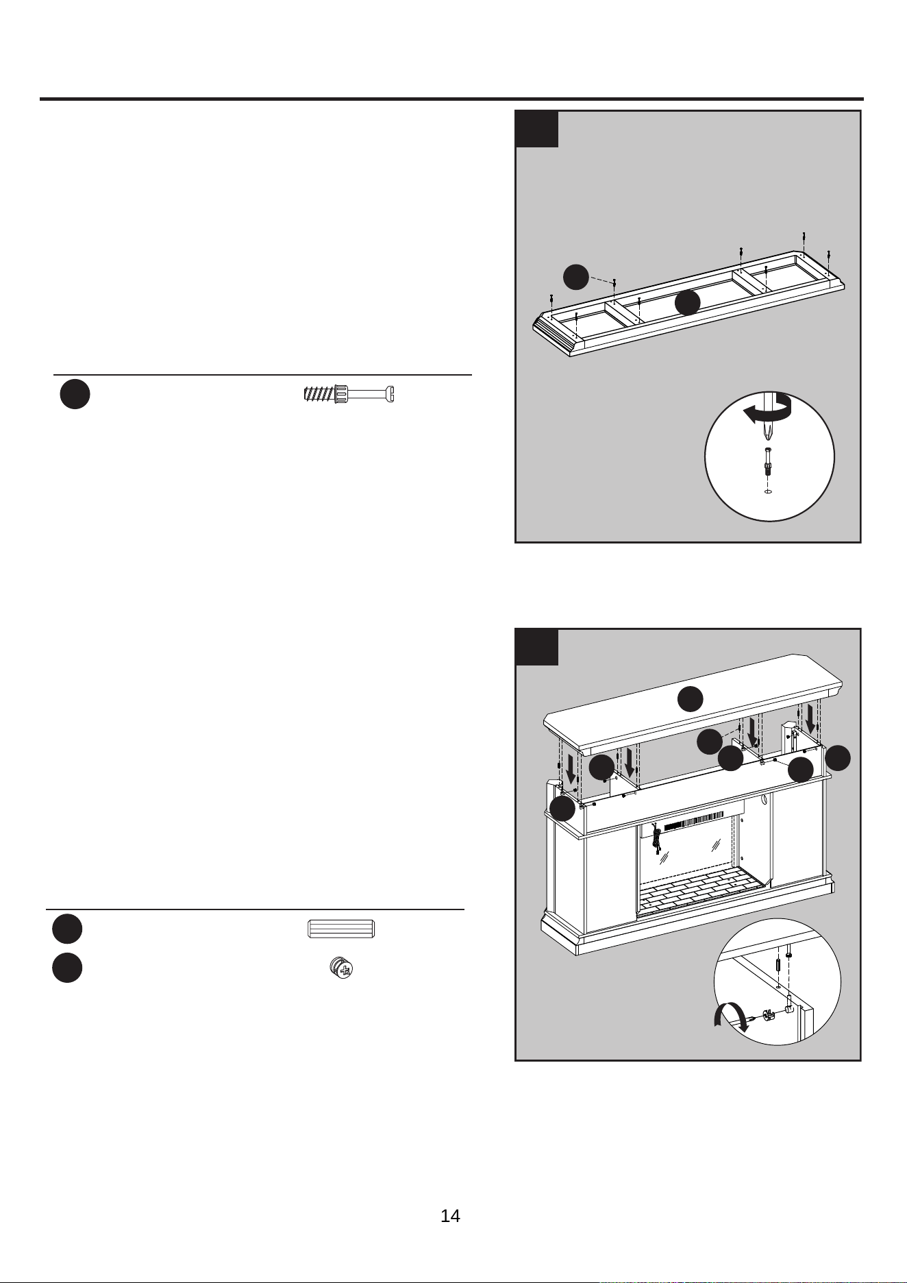
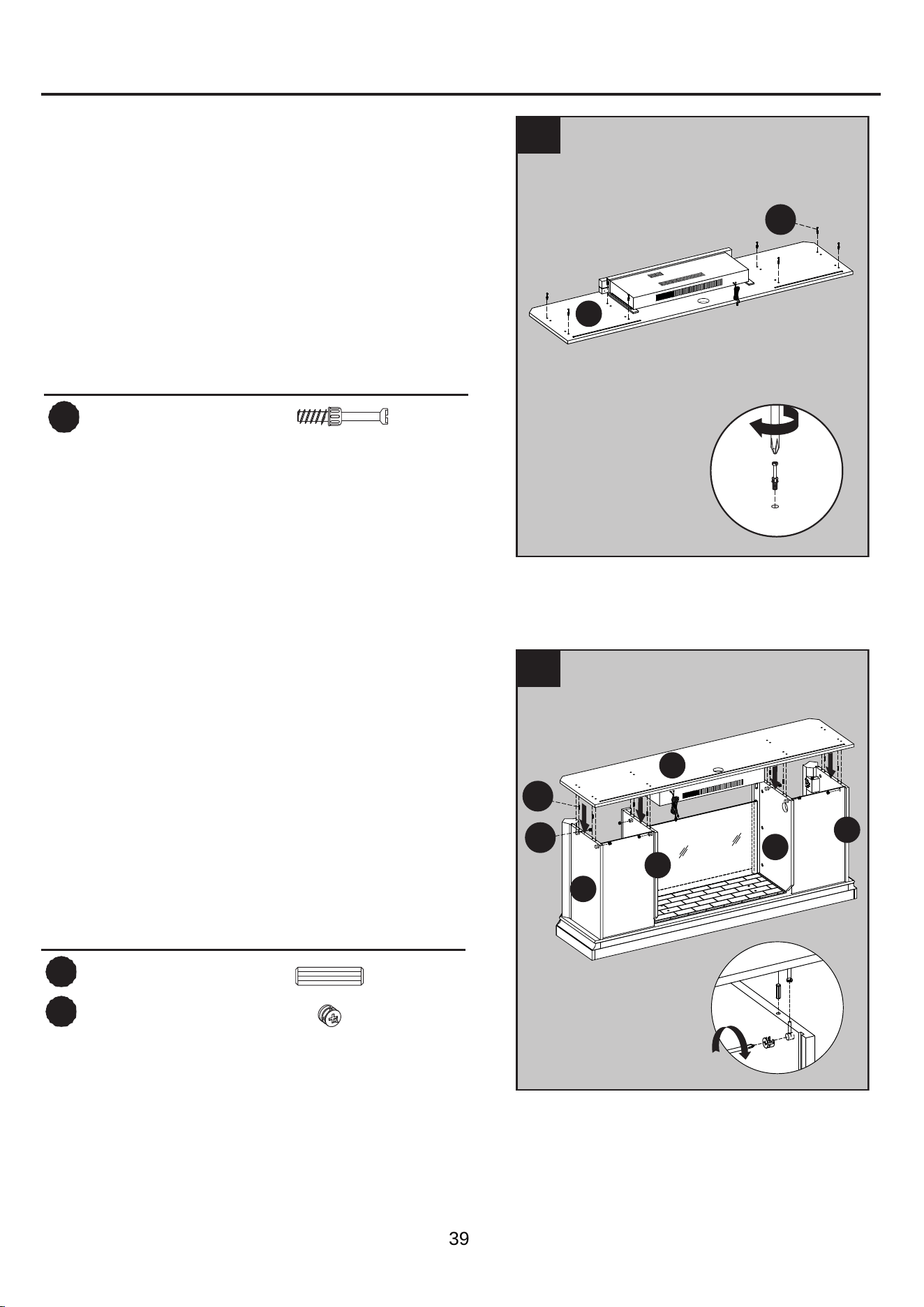
6. Screw eight connecting rods (CC) into the
designated holes on the top of the center
shelf and heater (D).
Hardware Used
CC
Connecting Rod
x 8
6
7
CC
D
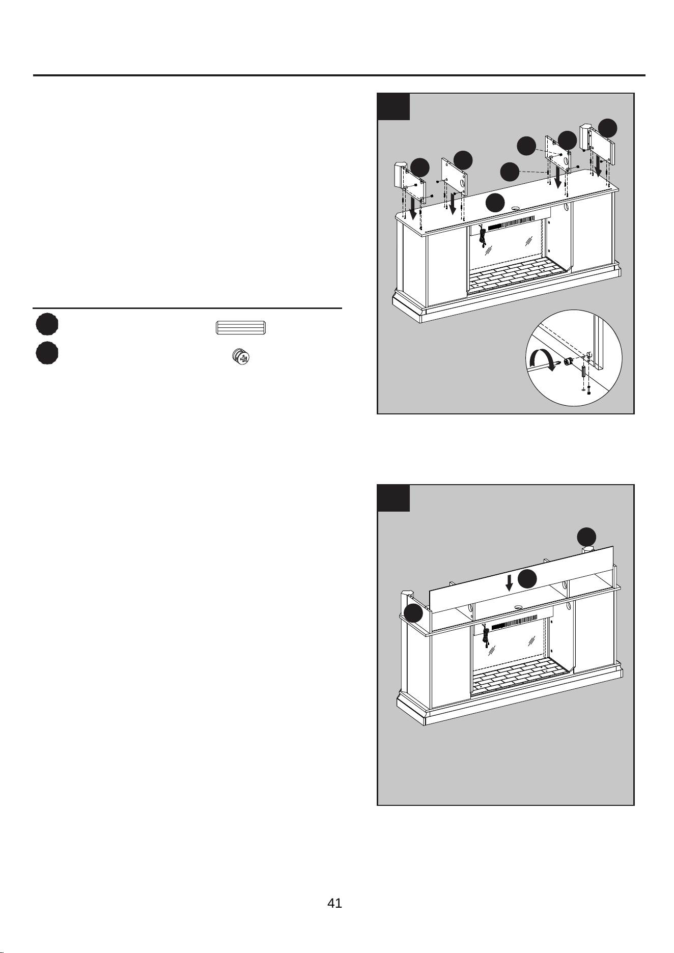
7. Insert ten wooden dowels (AA) into the top
outer holes of the outer walls (G) and middle
walls (E, F). With assistance from another adult,
align the holes in the center shelf and heater (D)
with the inserted dowels and lower into place.
Secure the center shelf and heater (D) to the
middle walls (E, F), outer walls (G) using eight
locknuts
(DD).
Hardware Used
AA
Wooden Dowel
x 8
DD
Locknut
x 8
2
1
1
1
1
AA
DD
D
G
F
E
G
11
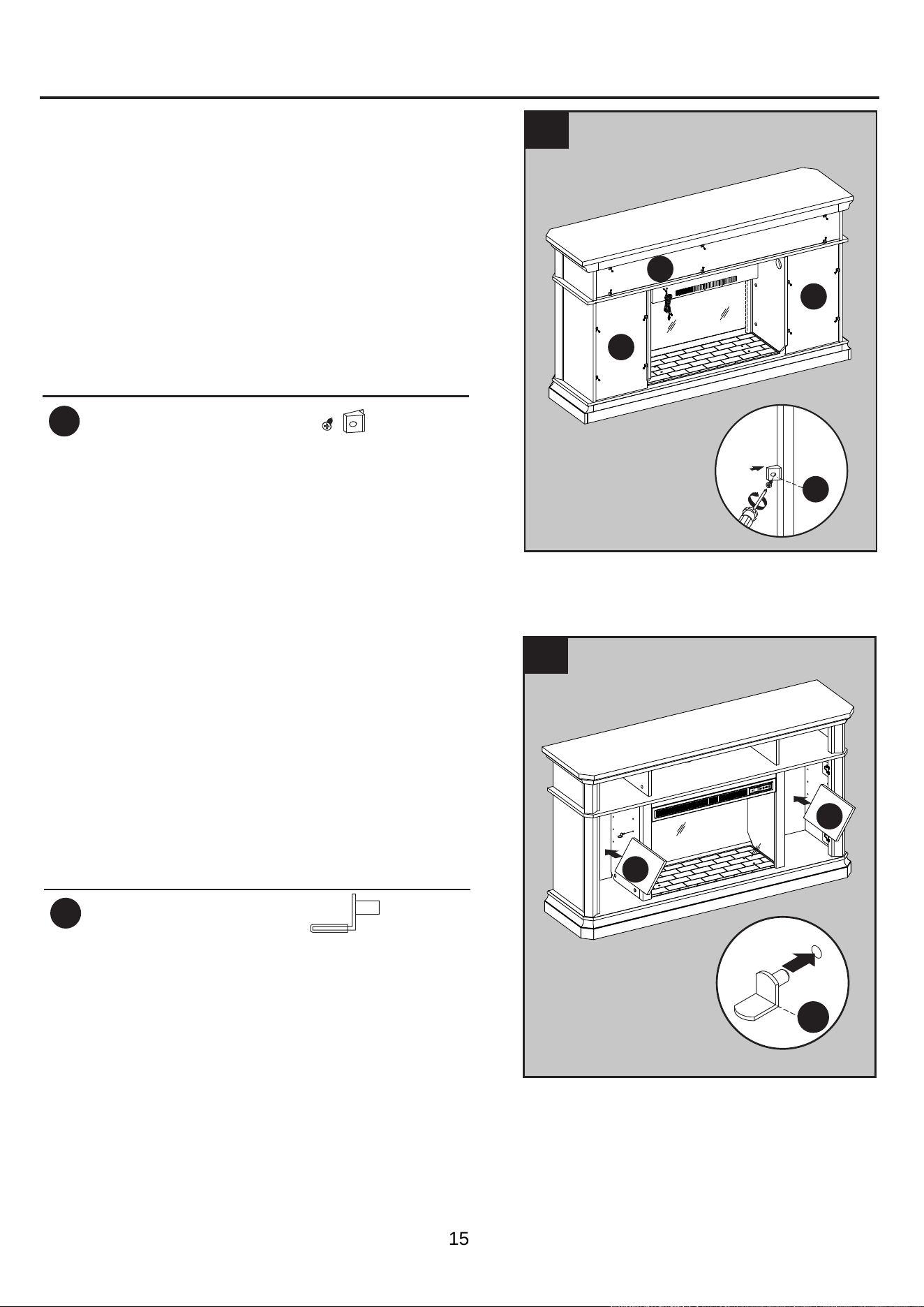
ASSEMBLY INSTRUCTIONS
Hardware Used
BB
Short Screw
x 2
1
2
BB
8
D
F
E
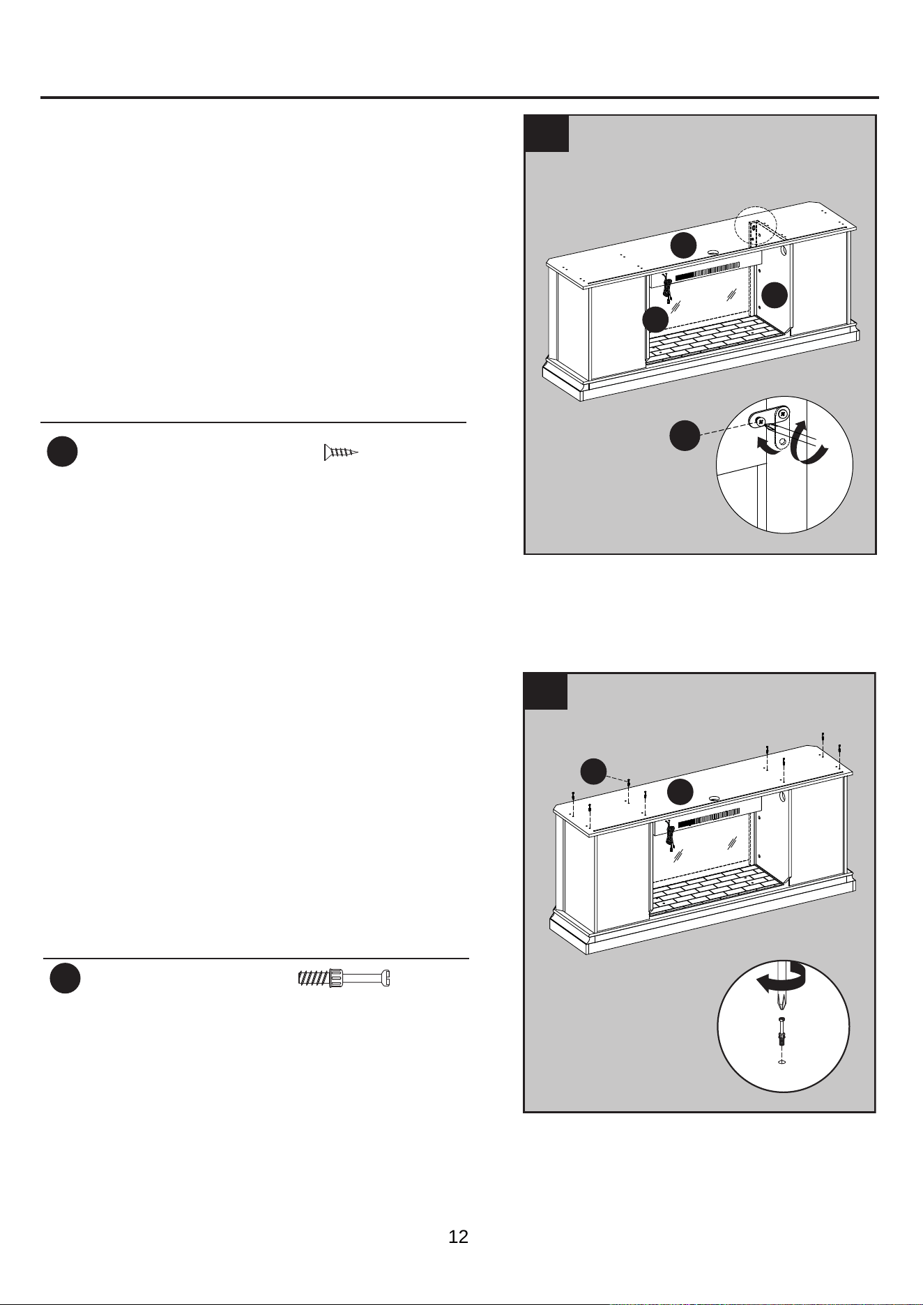
9. Screw eight connecting rods (CC) into the
designated holes on the top of the center
shelf and heater (D).
Hardware Used
CC
Connecting Rod
x 8
9
CC
D
8.
Adjust the metal plate of the left middle wall
panel (E)
and right middle wall panel (F) to
align with
the corresponding holes on the
center shelf
and heater (D)
. Secure the
center shelf and heater (D) with two short
screws (BB).
12
ASSEMBLY INSTRUCTIONS (CONTINUED)
1
11
1
0
1
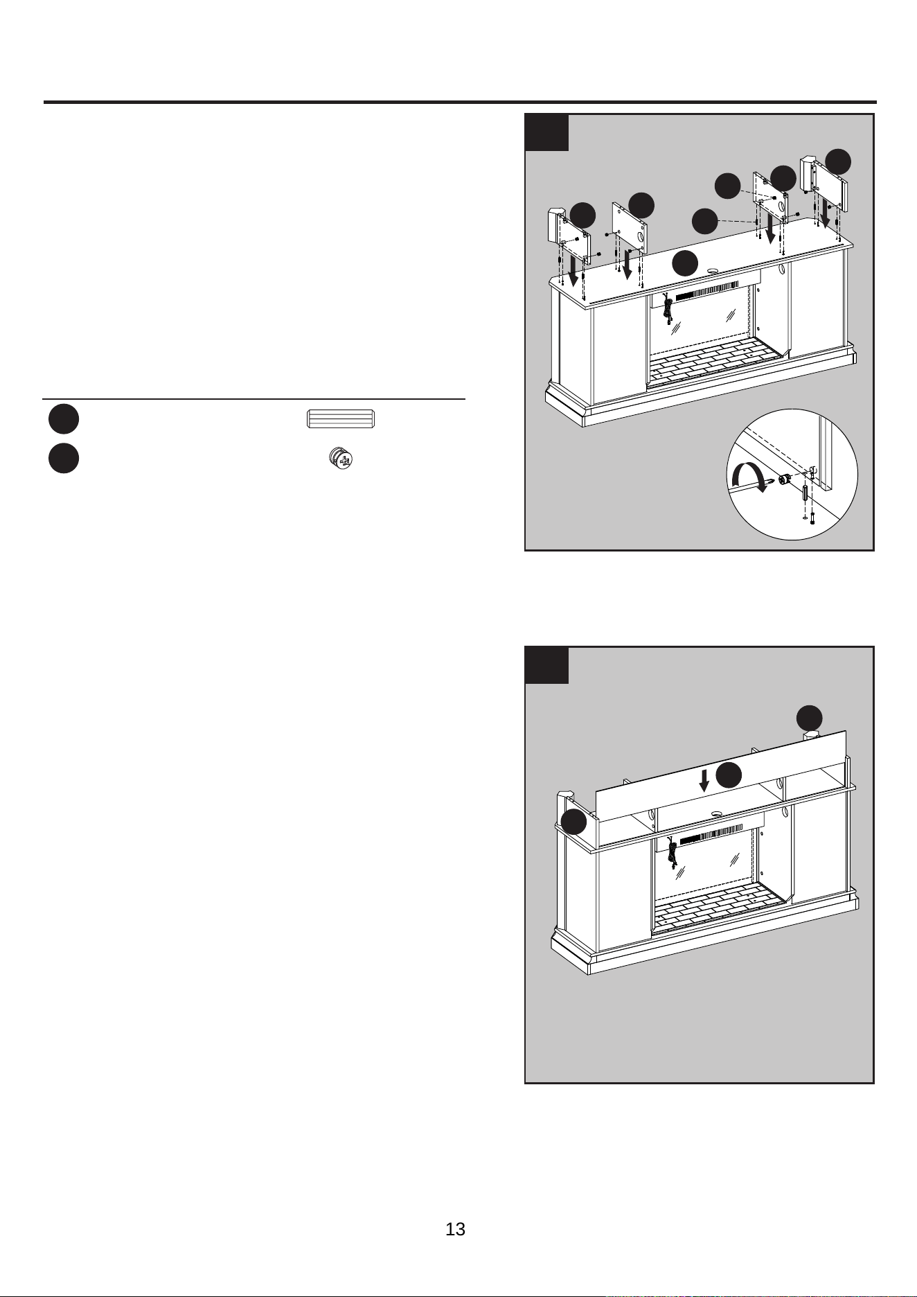
10.
Insert wooden dowels (AA) into the top holes of
the center shelf and heater (D), align the holes
in the corner panels (B) and the partition panels
(C) with the inserted dowels and lower into place.
Secure the corner panels (B) and partition
panels (C) to the center shelf and heater (D)
using eight locknuts (DD).
Hardware Used
AA
Wooden Dowel
x 8
DD
Locknut
x 8
1
1
1
DD
AA
B
D
B
C
C
2
K
As shown in the diagram, insert the center
back panel (K) along the grooves of the corner
panels (B).
B
B
11.
13
ASSEMBLY INSTRUCTIONS (CONTINUED)
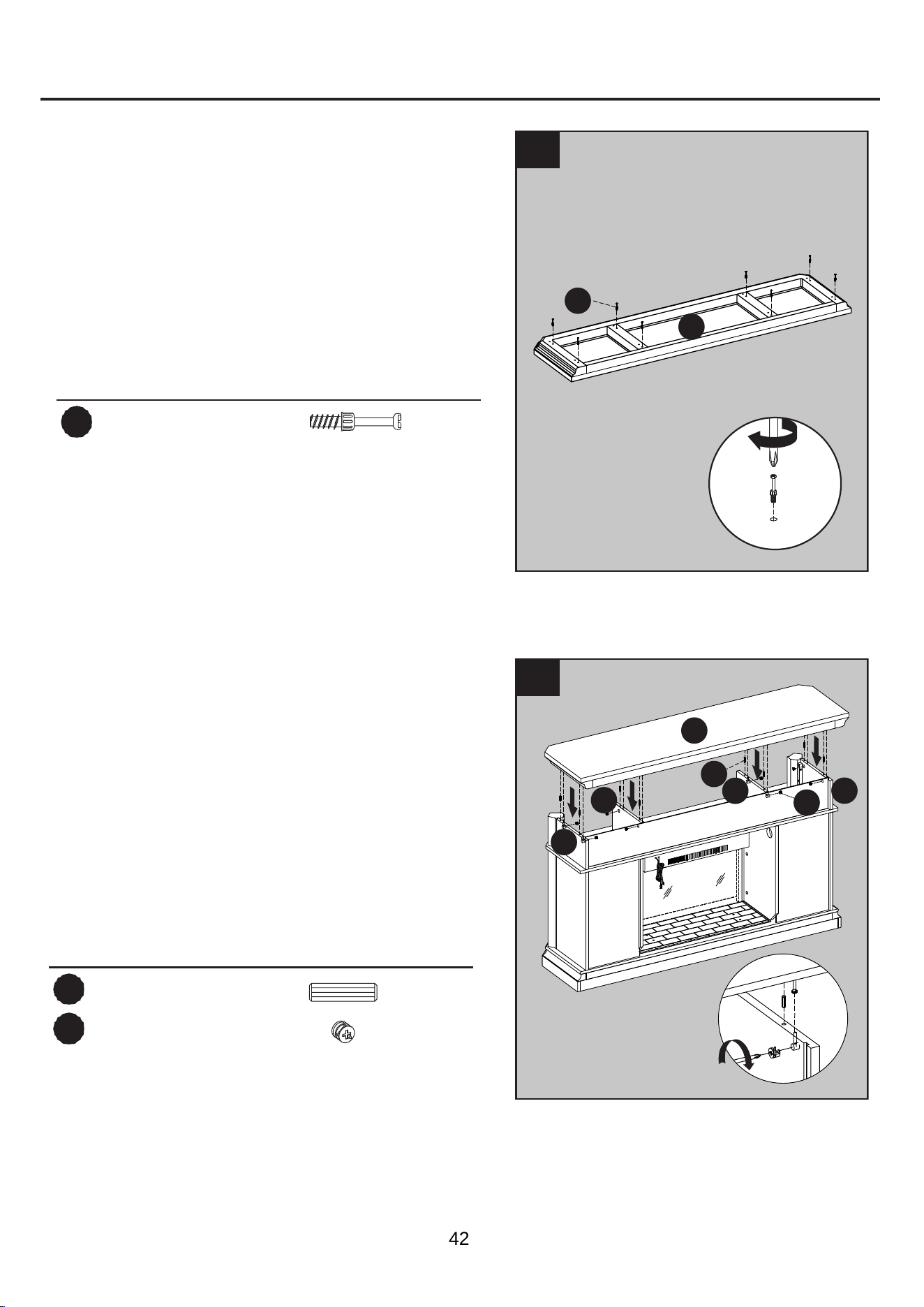
12.
12
13.
Screw eight connecting rods (CC) into the
designated holes on the back of the top (A).
Hardware Used
CC
Connecting Rod
x 8
13
CC
A
2
A
Hardware Used
AA
Wooden Dowel
x 8
DD
Locknut
x 8
Insert wooden dowels (AA) into the top holes of
the corner panels (B) and the partition panels
(C), align the holes in the top (A) with the
inserted dowels and lower into place. Secure
the top (A) to the corner panels (B) and the
partition panels (C) using eight locknuts
(DD).
AA
DD
B
B
C
C
B
1
1
1
1
14
ASSEMBLY INSTRUCTIONS (CONTINUED)
14.
14
15.
EE
1
2
Secure the back panels (L) and center back
Hardware Used
EE
Back panel mounting
hardware with screw
x 14
K
L
L
Insert the shelf pins (FF) at the desired height,
ensuring they are level. Place the shelf (H) on
top of the shelf pins (FF).
Repeat for the remaining shelves (H).
15
1
FF
Hardware Used
FF
Shelf Pin
x 8
2
2
H
H
panel (K) to the product using the back panel
mounting hardware with screw (EE), screwing
the screws by Phillips screwdriver (As shown in
diagram
14).
15
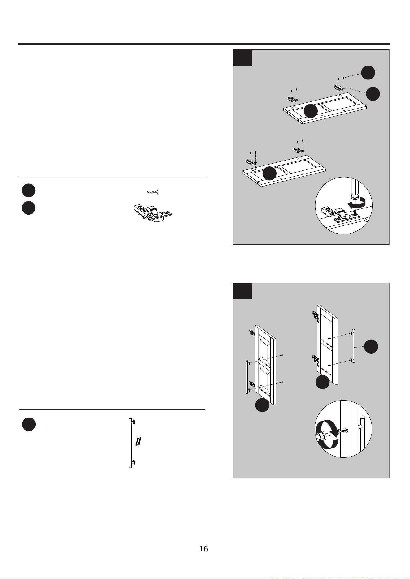
ASSEMBLY INSTRUCTIONS (CONTINUED)
Hardware Used
16
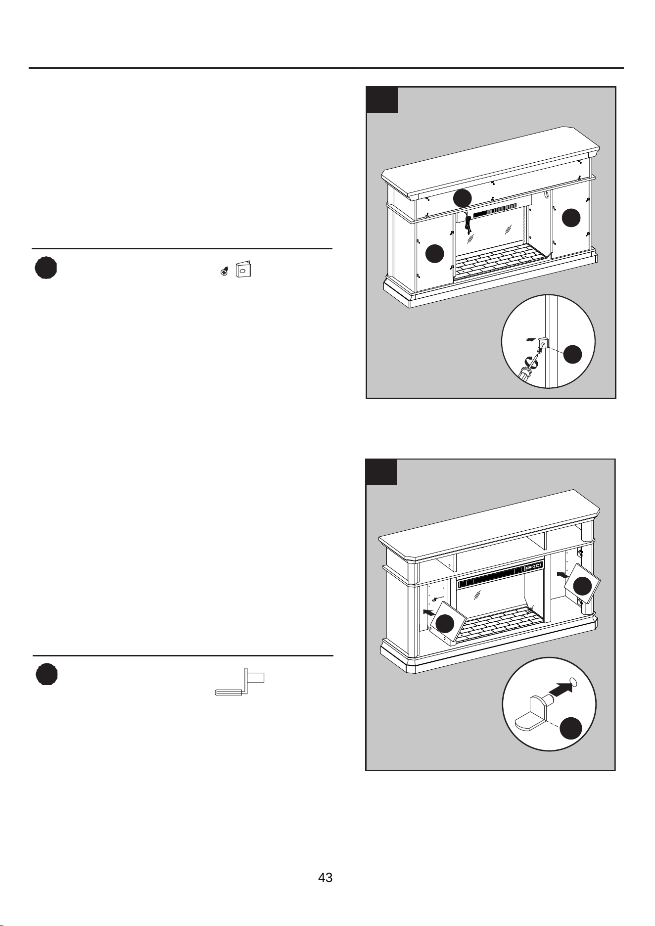
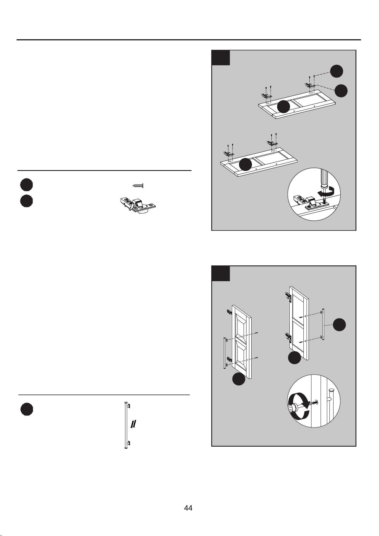
17.
Place the hinges (HH) into predrilled hole on
the door (I), securing with two hinge screws
(GG).
Repeat for the remaining hinges (HH).
Hardware Used
GG
Hinge Screw
x 8
HH
x 4Hinge
17
GG
HH
16.
II
Door Pull
x 2
Place the door pull (II) into predrilled hole
on the door (I), securing with two door pull
screws.
Repeat for the remaining door pull (II).
I
I
I
I
II
16
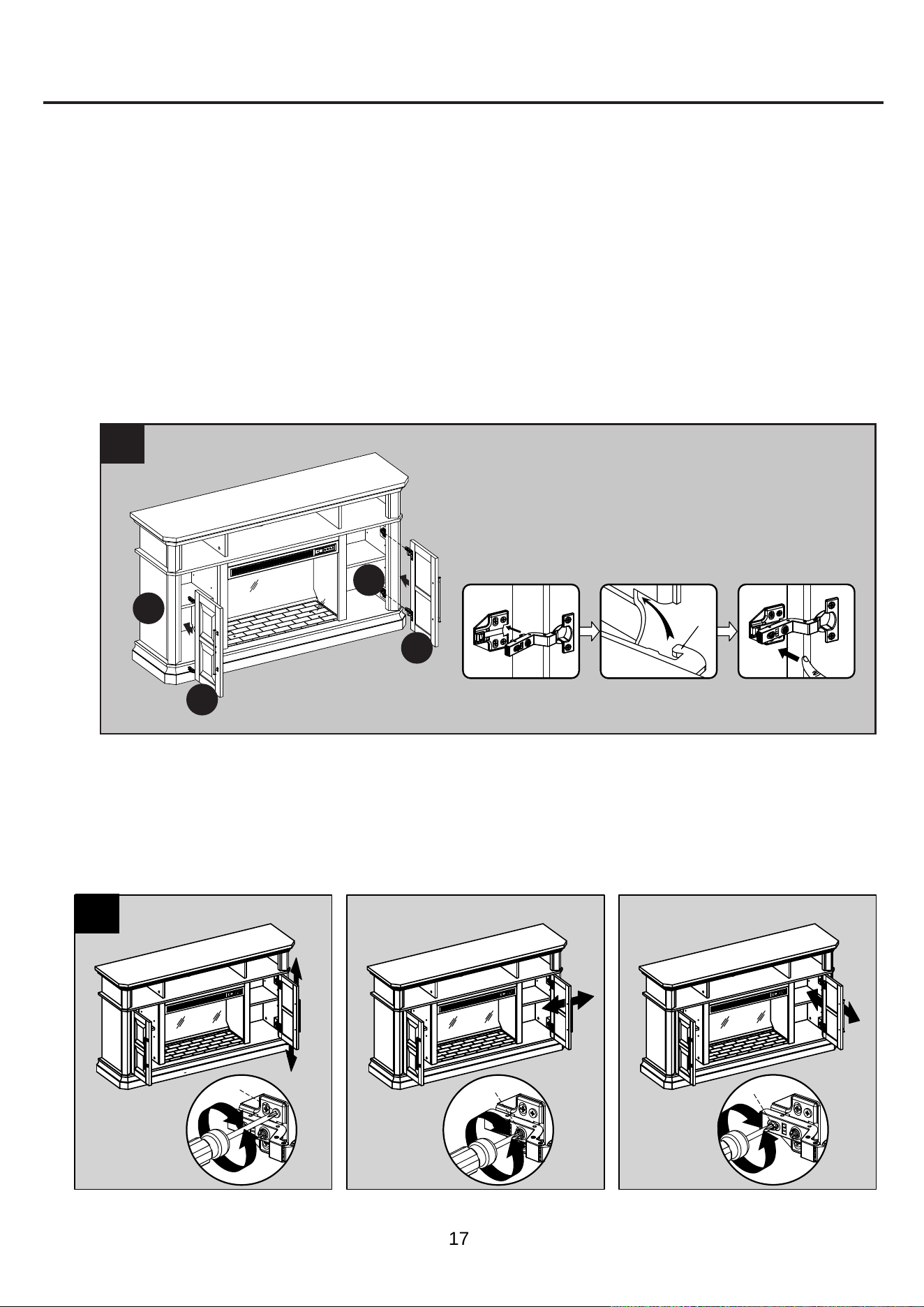
ASSEMBLY INSTRUCTIONS (CONTINUED)
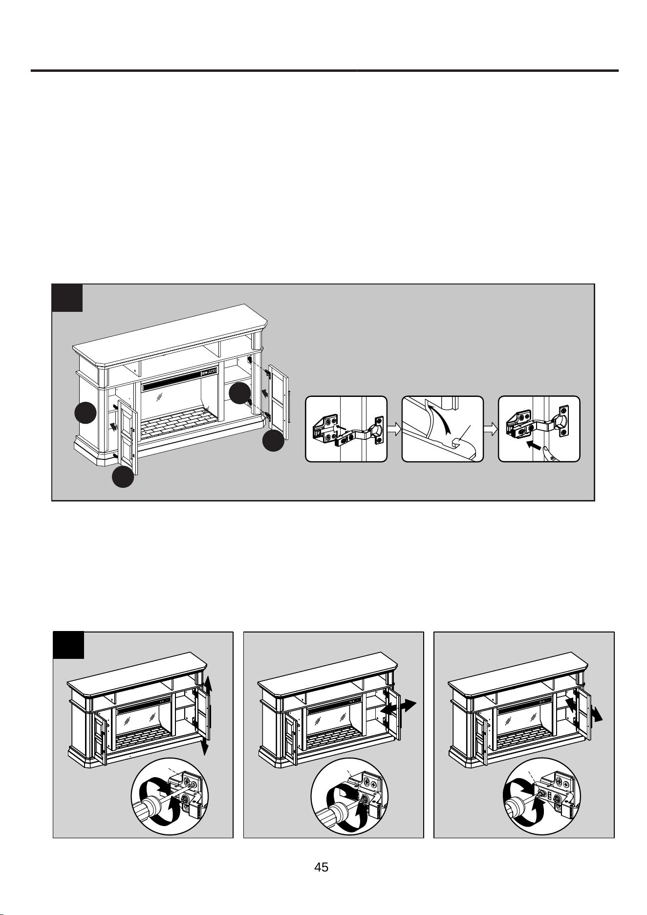
18.
Install the doors
18
I. Pick up door (I) and attach it to left outer wall (G) by engaging both door hinges
simultaneously. Please follow the steps below to combine the door hinges together.
i. Extend both hinge arms on the door (I) to open position.
ii. Insert the “J” hooks beneath the hinge arms into the lugs on mounting plates pre-attached on
left outer wall (G).
iii. Press lightly on the end of both hinge arms to engage the catch.
iv. To remove the hinge arms from the mounting plates, press gently in the release lever on the
back of hinge arms.
II. Repeat the same procedure to attach the other door (I) at the opposite side.
III. Open and close the doors to make sure they are aligned and shut correctly. If necessary,
adjust the screws for a good fit.
“J” hook
(ii)
(i)
(iii)
19. If you need to adjust the doors, do so in the following manner.
To adjust door up or down, loosen screws (a) on both hinges, adjust door, and retighten screws.
To adjust door left or right, turn screws (b) on both hinges, in and out.
To adjust door in or out, loosen screws (c) on both hinges, adjust door, and retighten screws.
19
2
2
2
2
2
2
a
1
1
b
1
1
c
1
1
I
I
G
G
17

ASSEMBLY INSTRUCTIONS (CONTINUED)
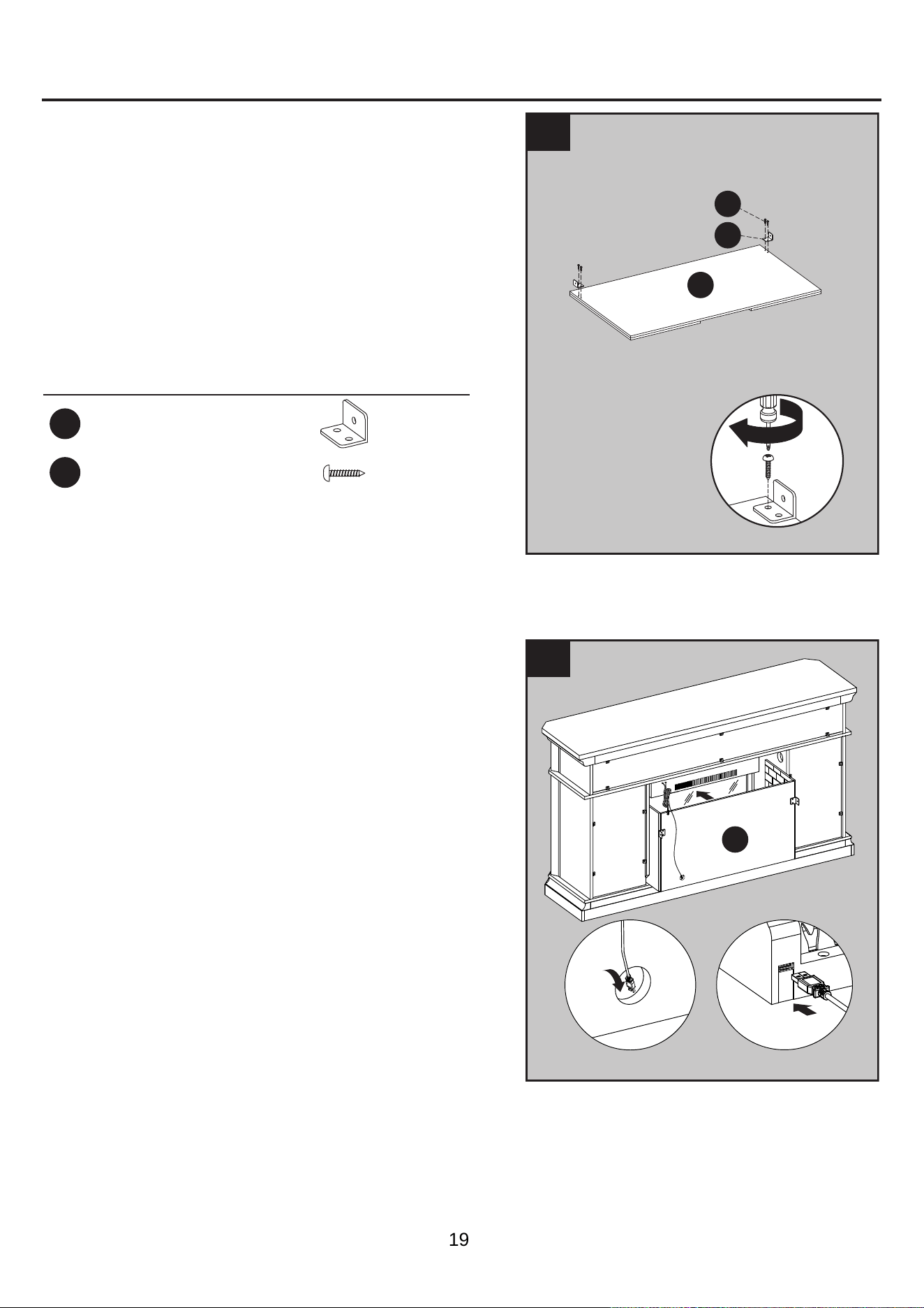
20.
20
21.
21
Hardware Used
JJ
Long Screw
x 2
JJ
N
Q
2
1
M
N
1
2
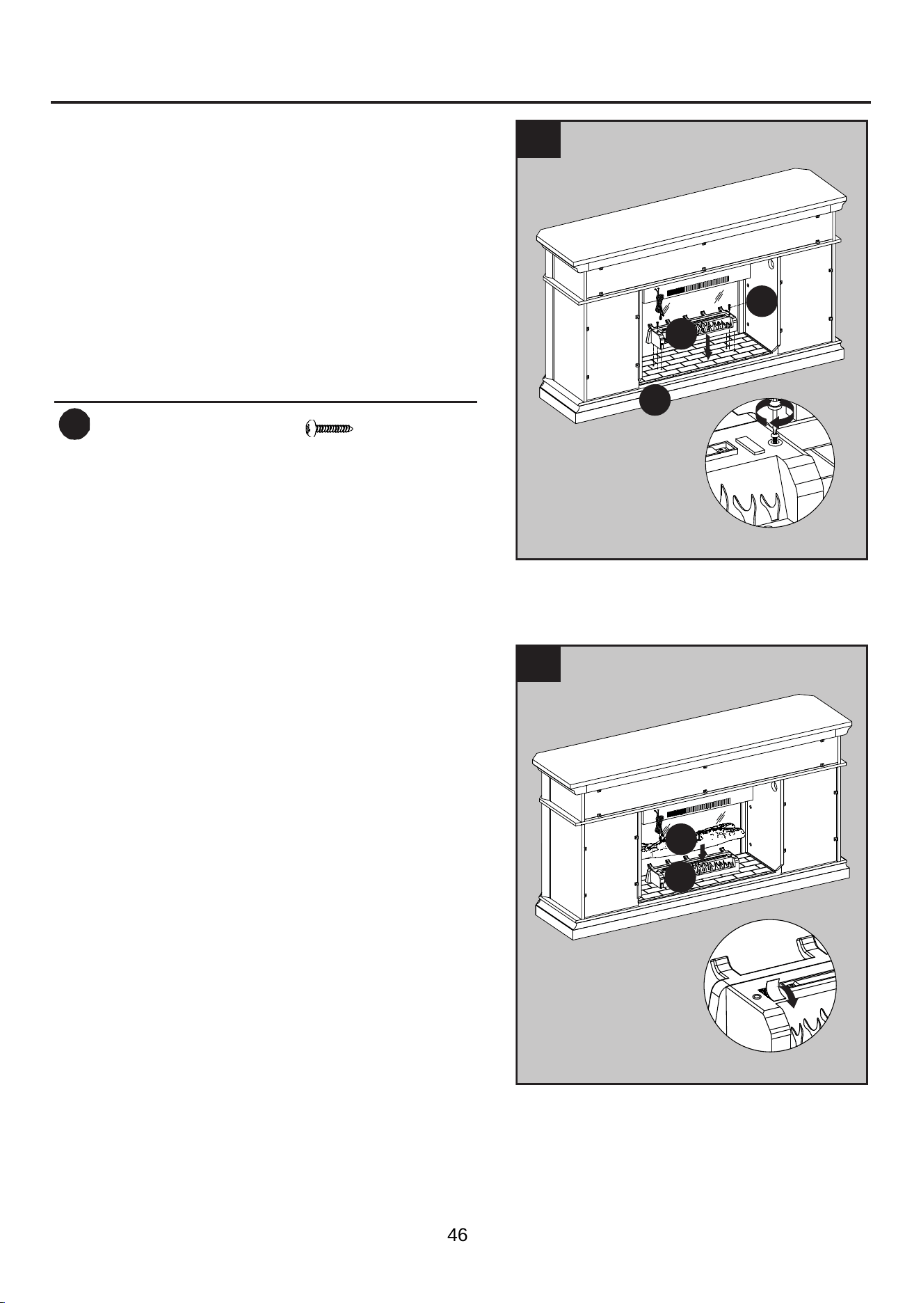
Place the fireplace grate (N) by inserting the
bottom pins into the holes in the
base (Q),
securing with two long screw (JJ) by
Phillips
screwdriver.
Remove the film from the adhesive on the top
of the fireplace grate (N) and place the fire log
(M) on the center of the fireplace grate (N).
18
ASSEMBLY INSTRUCTIONS (CONTINUED)
22.
22
23.
Hardware Used
KK
L-Bracket
x 2
LL
Screw
x 4
23
LL
J
KK
3
2
1
Insert the fi
replace brick wall (J) into the
mantel by haft way, put the USB cable
from the heater
pass through the hole
on the back of
fireplace brick wall (J).
Attach the USB
cable into the
USB port
behind the
fi
replace grate (N).
J
Screw two L-bracket (KK) onto the fireplace
brick wall (J) using four screws (LL).
19
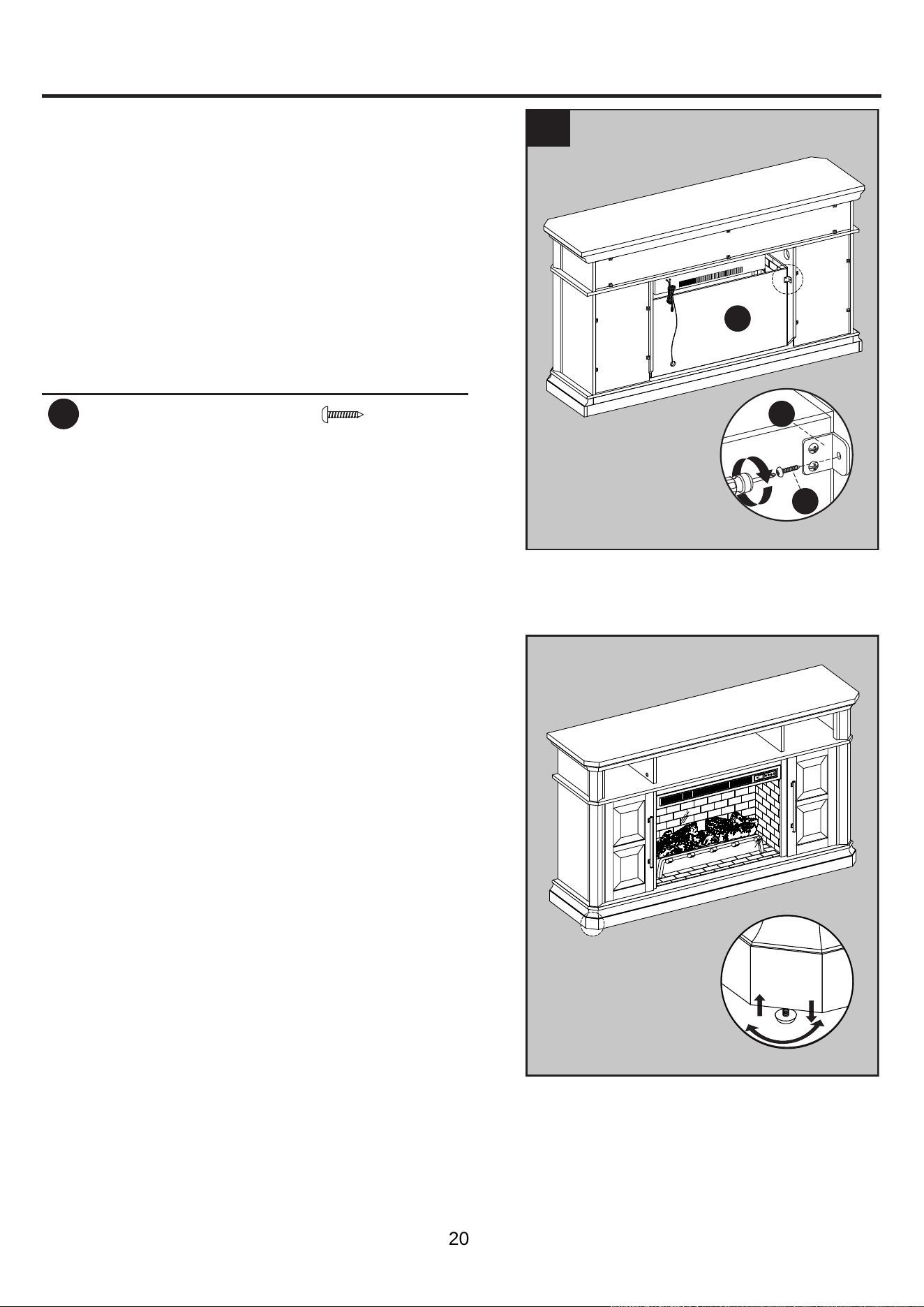
ASSEMBLY INSTRUCTIONS (CONTINUED)
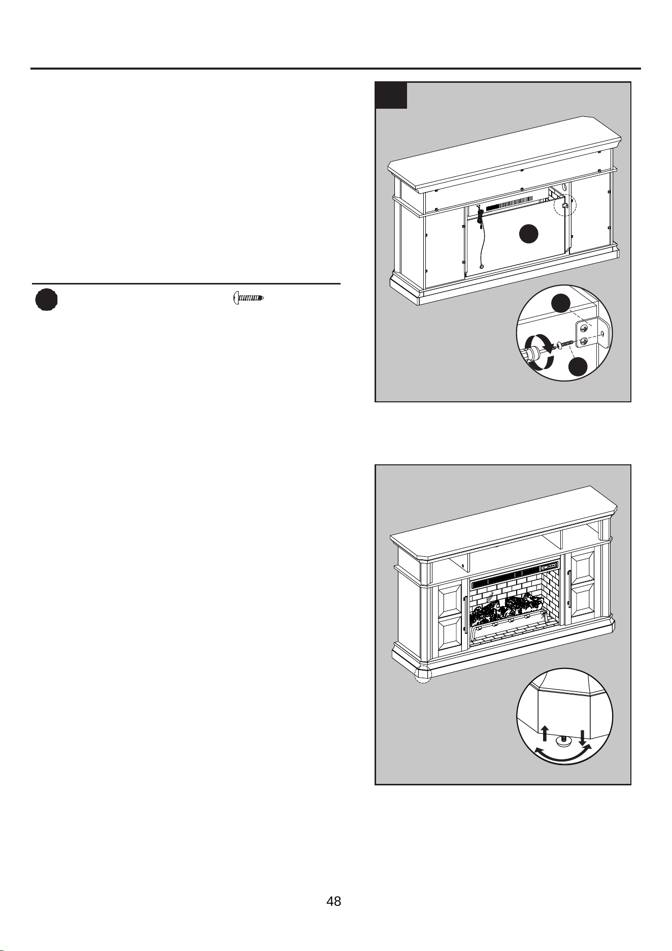
24. Insert the fireplace brick wall (J) into the
mantel, slotting it into the grooves on the base
(Q
). Secure it by using two screws
(LL) into
the L-bracket (KK).
Hardware Used
LL
Screw
x 2
24
LL
KK
J
NOTE:
Use the pre-assembled levelers on the base of
the fireplace to level the unit. Twist the levelers
counterclockwise to increase the height, twist the
levelers clockwise to decrease the height.
20
ASSEMBLY INSTRUCTIONS (CONTINUED)
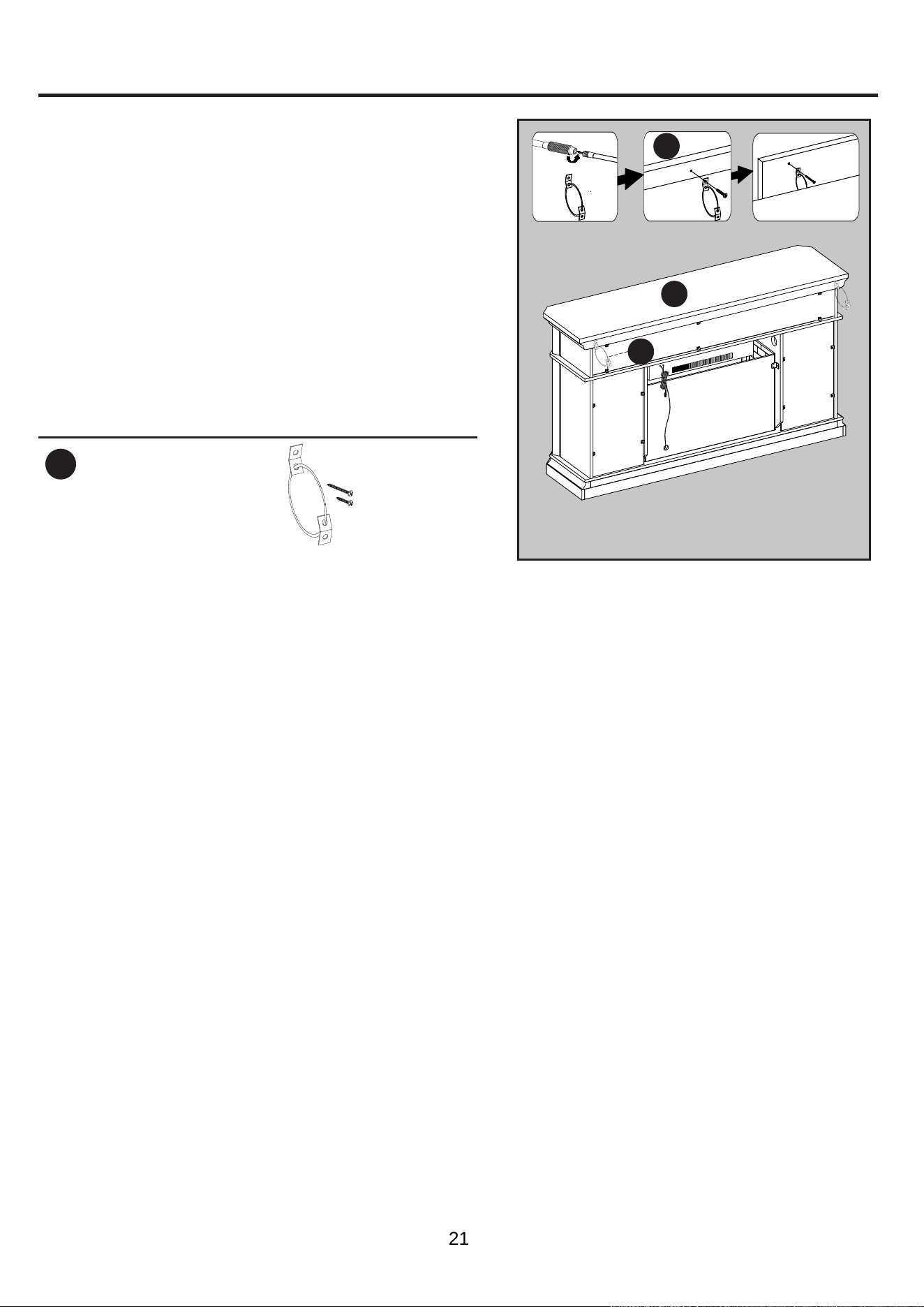
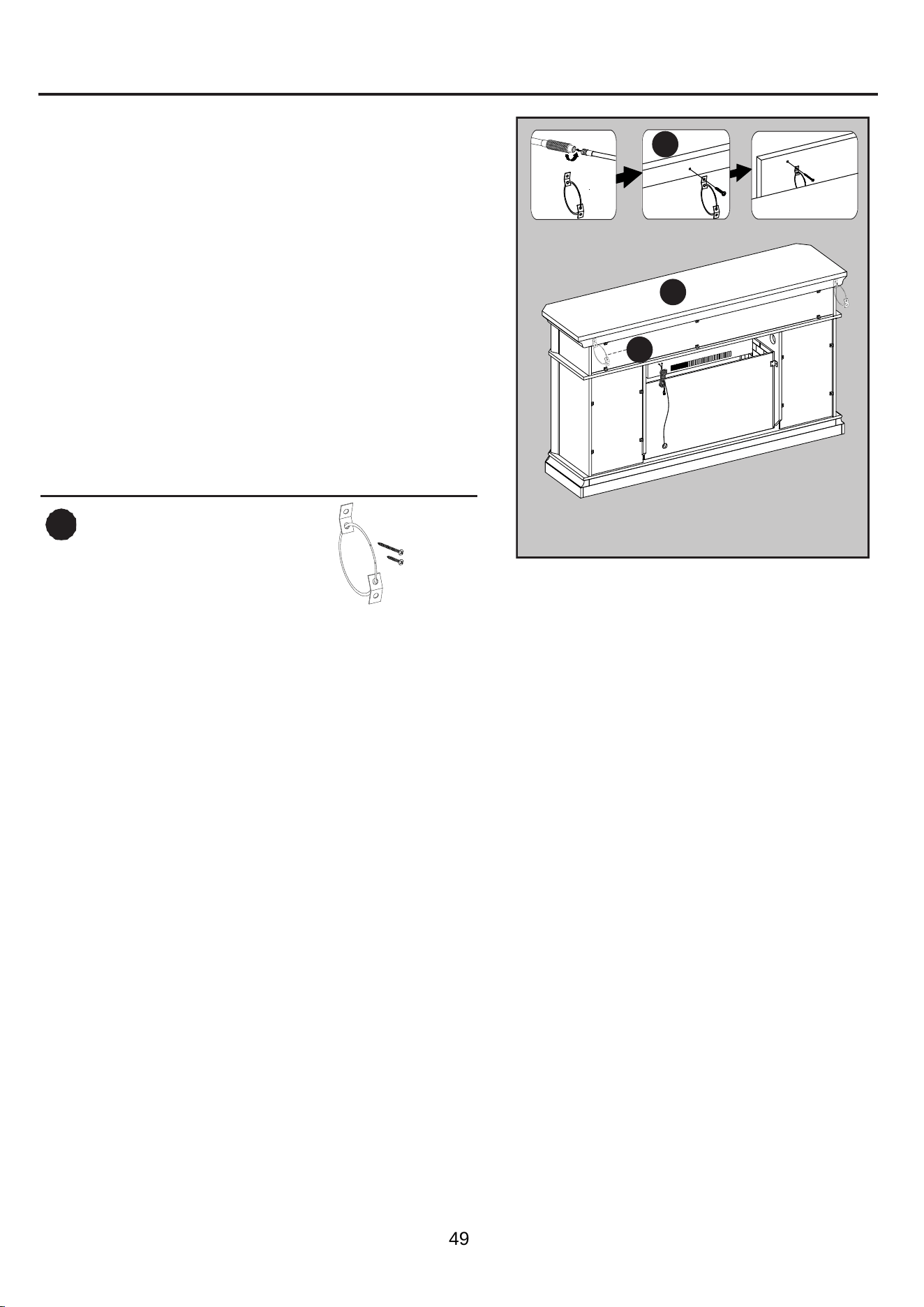
WARNING: You must install the tip restraint
hardware to help prevent any accidents or damage
to the unit. We strongly recommend attaching the tip
restraint hardware to a wall stud and your unit. For
all other wall types, please visit your local hardware
store to obtain the proper hardware.
Assembly is now complete. With the help of another
person, move the unit to the final desired position.
Once in the final position, you may attach the tip
restraint hardware to the wall. You may now plug
the heater into the power outlet.
Hardware Used
NN
Wall Stud
1
2
3
(i) (ii)
(iii)
x 2
NN
A
A
Hardware
Tip Restraint
21

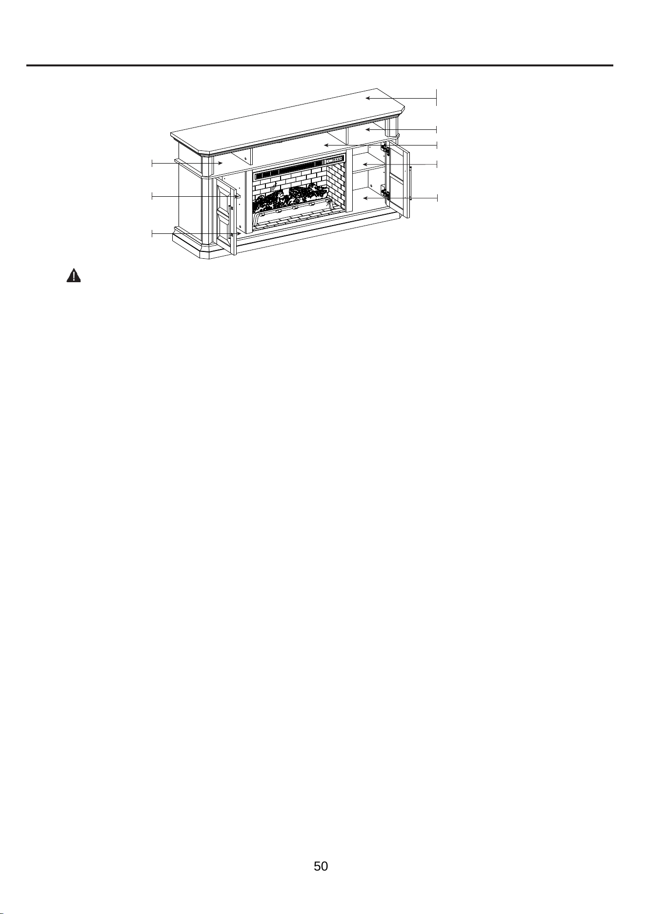
MAXIMUM RECOMMENDED WEIGHT LOADS
CAUTION: This console is intended for use with flat panel TV’s only. Do not exceed the maximum
weights indicated. Use with products heavier than the maximum weights may result in instability causing
possible injury.
MAXIMUM LOAD 16.36 kg / 36 lb
MAXIMUM LOAD 4.54 kg / 10 lb
MAXIMUM LOAD 4.54 kg / 10 lb
MAXIMUM LOAD 6.8 kg / 15 lb
MAXIMUM LOAD 4.54 kg / 10 lb
MAXIMUM LOAD 4.54 kg / 10 lb
FITS UP TO MOST 132.08 cm / 52 in FLAT PANEL TVS
MAXIMUM LOAD 22.72 kg / 50 lb
MAXIMUM LOAD 6.8 kg / 15 lb
22
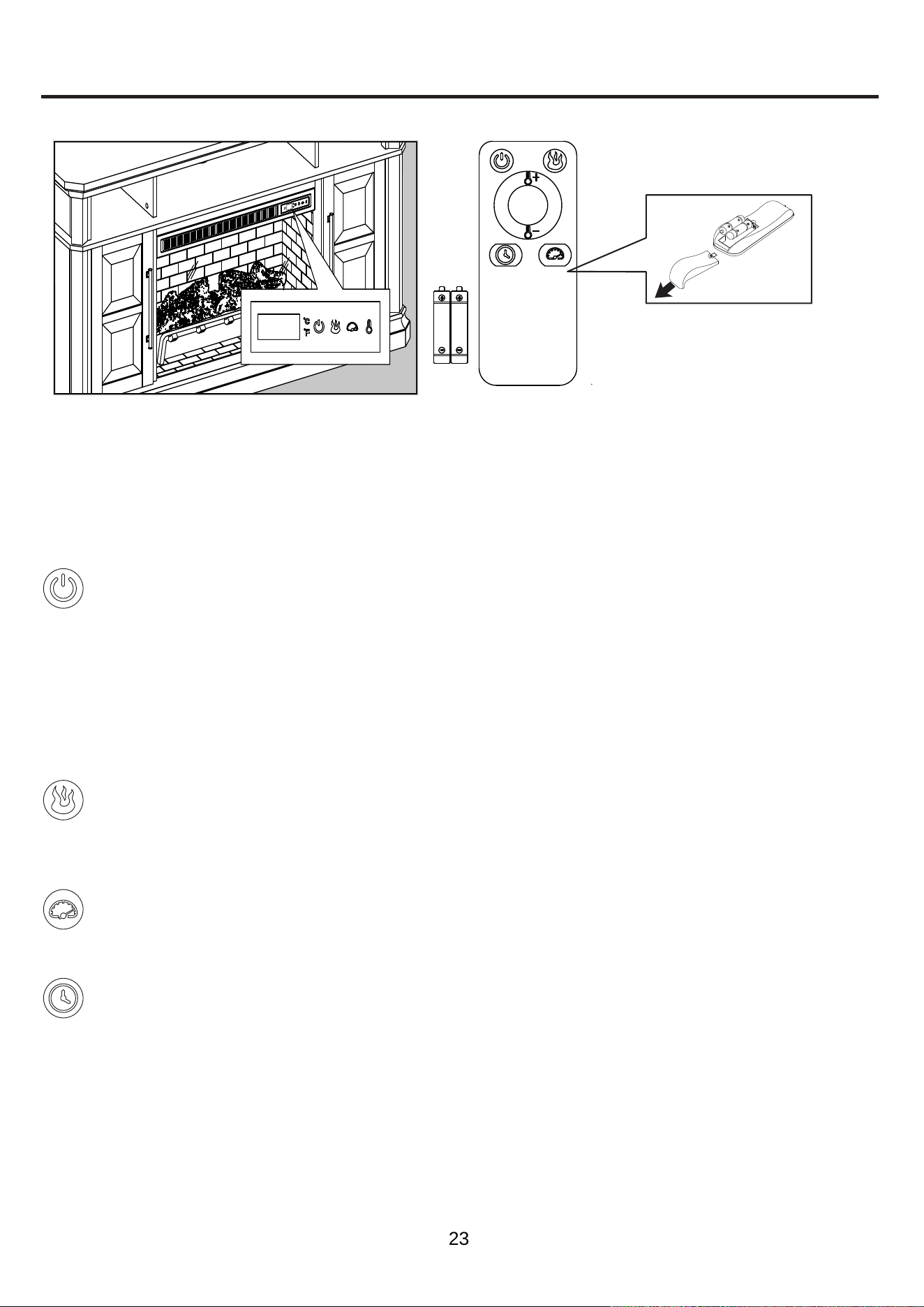
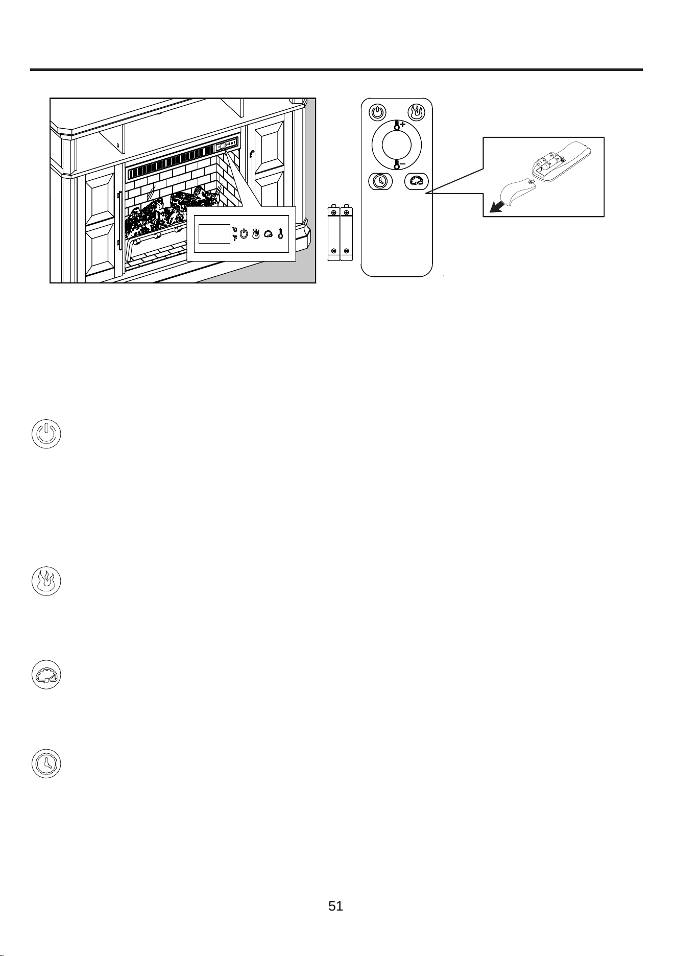
OPERATING INSTRUCTIONS
Remote ControlControl Panel
Controls and Display
The control panel will display the heater setting when the unit power is turned ON. Whichever control icon
you press will display the current setting of the corresponding function. Press the control icon again to adjust
the setting. Following adjustment of any setting(s), the unit will resume to display the heater setting after 5
seconds.
Power Function
• When the unit is plugged-in but not in use, F or C will illuminate to indicate that it is in stand-by
mode.
• Press the POWER ICON to turn the main power to the unit ON or OFF.
•
When the unit is powered ON, the control panel will display the heater setting to indicate the unit
has power.
•
Functions stored in memory will resume at the last setting.
•
When the unit is powered OFF, the fan will continue to blow for a 40 second cool-down cycle prior
to shutting down (a countdown will be displayed).
Flame Brightness Function
• Press the FLAME BRIGHTNESS ICON to display the current ame brightness setting.
•
Press the FLAME BRIGHTNESS ICON again to scroll down through the ame brightness settings:
5, 4, 3, 2, 1, oF (OFF).
Flame Speed Function
• Press the FLAME SPEED ICON to display the current ame speed setting.
• Press the FLAME SPEED ICON again to scroll down through the ame speed settings: 5, 4, 3, 2, 1.
Sleep Timer Function (Remote Control Only)
• The Sleep TIMER function will set a countdown to shut down the unit’s main power.
•
Press the TIMER ICON to display the current Sleep Timer setting.
• Press the TIMER ICON again to scroll through the timer settings, which are: 30 (minutes), 1H, 2H,
3H, 4H, 5H, 6H, 7H, 8H, 9H, oF (OFF).
• When the timer reaches zero, it will turn OFF the main power and will maintain all the settings in
memory.
To use the remote control, first insert two
AAA batteries (included) into the remote
control. Ensure the polarities of the
batteries match the inside of the battery
compartment.
23
OPERATING INSTRUCTIONS (CONTINUED)
• You can scroll upwards or downwards through the heater settings using the remote control for
added convenience.
• Press the PLUS ICON to scroll upwards through the heater settings.
• Press the MINUS ICON to scroll downwards through the heater settings.
HEATER OVERRIDE
The power to the heater can be disengaged to prevent the heater from being accidentally or unintentionally
powered on. This feature is primarily added to help prevent children from powering on the heater when it is not
desired.
Note: The heater override can only be set from the control panel and will not work if using the remote control.
•
First turn the main power OFF. Press the POWER ICON; as the heater setting display is ashing, press the
POWER ICON again and long-hold 20 seconds. The E3 symbol will display to indicate that the heater is
now disengaged.
• Note: The Flame and Timer functions will operate normally. Only the heater is disengaged.
• Repeat the same process to re-engage the heater function. The E3 symbol will change back to display the
heater setting when the heater is re-engaged.
MEMORY FUNCTION
• This unit has a memory function that allows you to turn off the MAIN POWER and retains all the other
function settings (excluding the SLEEP TIMER function).
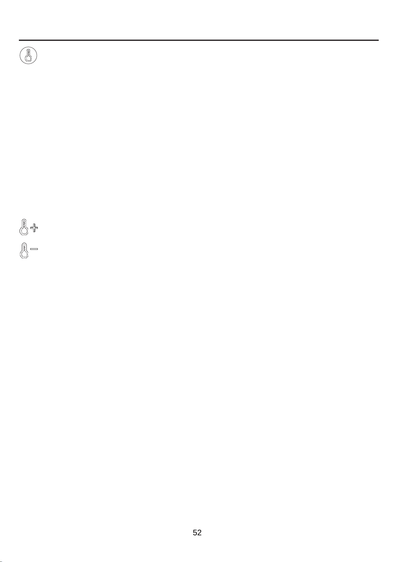
Heater Function (Control Panel Only)
•
Press the HEATER ICON to display the current heater setting.
•
Press the HEATER ICON again to scroll down through the heater settings.
Note:
Long-hold the icon to quickly scroll through settings.
•
Set the heater to “HI” (High) to have the heater run continually.
• Set the heater to “oF” (OFF) to use the ame functions without heat.
•
This heater has a thermostat sensor to control the ambient temperature in the surrounding area
of the fireplace. The heater will cycle ON and OFF to maintain the selected temperature. The
thermostat setting range is 90ºF (32°C) to 65°F (18°C), HI (High) and oF (OFF).
Note:
This may not exactly match the room thermostat reading as their sensors are located in
different areas.
•
Hold down the FLAME SPEED ICON for 10 seconds to toggle between Fahrenheit and Celsius. “F”
or “C” will be displayed on the control panel (°F/°C can only be toggled from the control panel and
will not work if using the remote control).
•
See HEATER OVERRIDE section to disengage the heater.
Adjusting the Heater Setting from the Remote Control
24
CARE AND MAINTENANCE
• Make sure the unit is turned OFF, unplugged and the heating elements of heater are cool whenever you are
cleaning the heater or fireplace.
• Clean the metal trim using a water-dampened soft, clean cloth. DO NOT use brass polish or household
cleaners as these products will damage the metal trim.
•
The motors used on the fan and the ame generator assembly are pre-lubricated for extended bearing life
and require no further lubrication. However, periodic cleaning/vacuuming of the fan/heater and air intake/
output vents are recommended.
•
When the heater is not in use, the power cord should be stored properly to avoid contact with hot or sharp
objects.
•
Any other servicing should be performed by an authorized service representative.
• Tips for using touch-up pen (MM): For scratches, stroke in direction of scratch. For worn areas, stroke in the
direction of wood grain. Rub excess colorant promptly with a soft cloth.
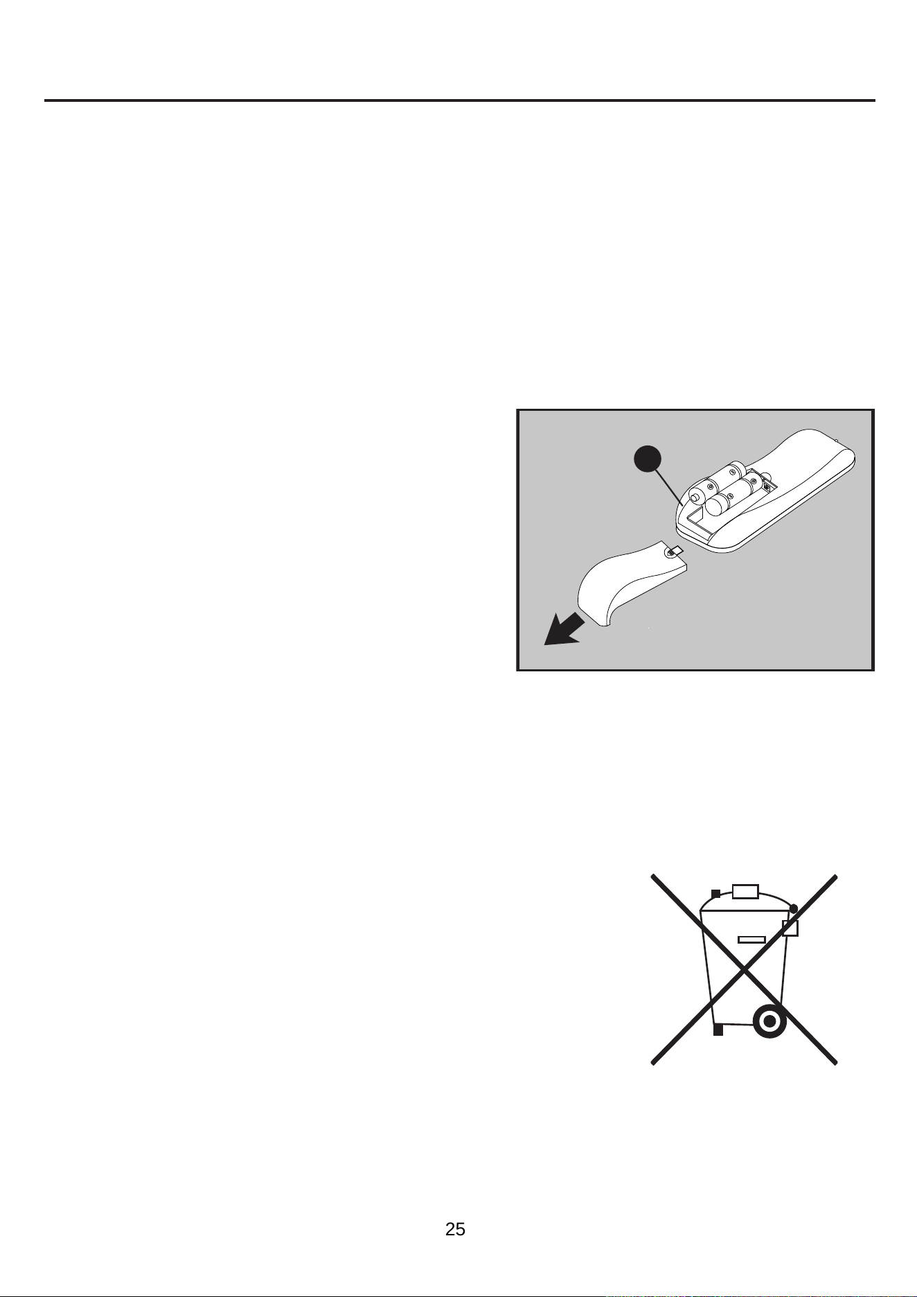
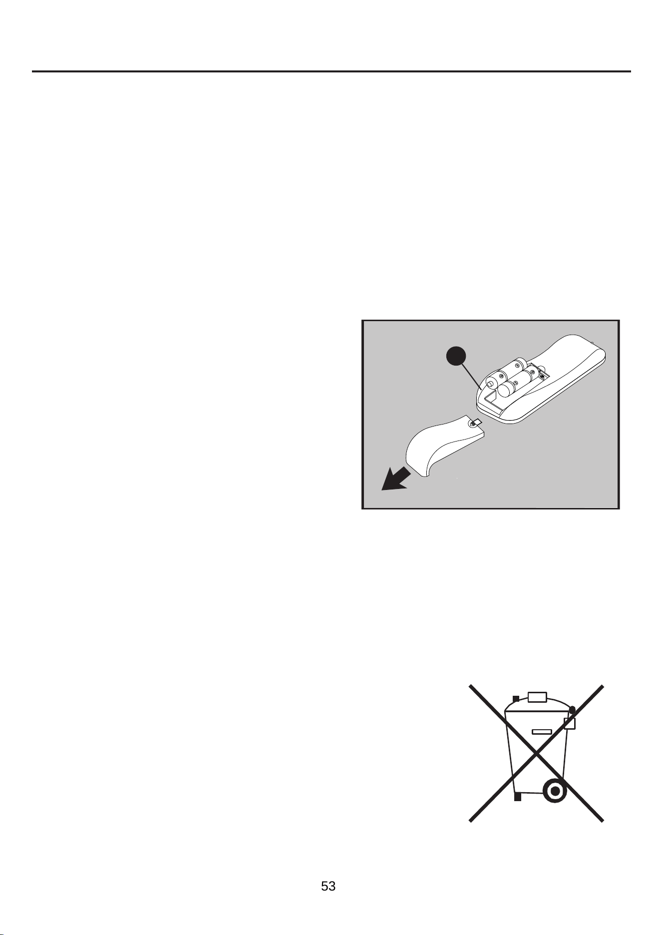
Replacing the Remote-Control Battery
When the remote control (O) stops operating or its range
seems reduced, it is time to replace the battery. Note: The
battery should be removed if the product is to be left unused
for a long time.
1. The battery compartment is located on the back end of the
remote control (O).
Disposal of Used Battery
A battery may contain hazardous substances that could be endangering the environment and human health.
• This symbol marked on the battery and/or packaging indicates that used
battery shall not be treated as municipal waste. Instead, it shall be left at
the appropriate collection point for recycling.
• By ensuring the used battery is disposed of correctly, you will help
prevent potential negative consequences for the environment and human
health. The recycling of materials will help to conserve natural resources.
• Do not dispose of battery in fire. Battery may explode or leak.
For more information about collection and recycling of used battery, please
contact your local municipality, your waste disposal service or the
point-of-sale where you purchased this battery.
and remove old batteries.
Insert 2pcs AAA batteries, ensuring the polarities of the
battery match the inside of the battery compartment.
Re-insert the battery door.
2.
3.
4.
Remove battery cover from the back of remote control (O)
Note:
Do not mix old and new batteries.
Do not mix alkaline, standard (carbon-zinc), or rechargeable (nicad, nimh, etc.) batteries.
Non-rechargeable batteries are not to be recharged. Exhausted batteries are to be removed from the
product.
Harmful if swallowed.
•
•
•
•
O
25

TROUBLESHOOTING
POSSIBLE CAUSEPROBLEM CORRECTIVE ACTION
Error E1 displayed on
control panel.
The overheat sensor has
been engaged.
Unplug unit, wait 15-20 minutes, then the sensor will reset
itself. Plug the unit back in and turn on the heater. If the
problem persists, call customer service.
Note: The other functions will work normally excluding the
heater.
Error E2 displayed on
control panel.
The thermostat sensor
is broken or not working
correctly.
Unplug unit, wait 15-20 minutes, then the sensor will reset
itself. Plug the unit back in and turn on the heater. If the
problem persists, call customer service.
Note: The other functions will work normally excluding the
heater.
Error E3 displayed on
control panel.
Heater override function is
engaged.
See page 24 Heater Override Section for more details.
The unit does not haveNo power.
power.
Check that the power cord is securely plugged into a
standard 120V outlet. Then check to make sure the unit is
powered on.
No ame effect but the
unit is powered on.
The ame effect is
powered off.
Push the ame brightness button until desired level is
achieved.
Connect the USB cable into the USB port behind theUSB cable.
Fireplace Grate.
Heater and blower
do not power on but
rest of functions are
working.
Set the heater to "HI" (High) to have the heater runHeater setting.
continually.
Power cord gets warm
to the touch.
This is normal for a heater appliance as it requires moreNormal operation.
current to operate. Check the connections of the appliance
cord and the outlet. Make sure the plug
fits tightly into the
outlet. During use, check the plug and outlet frequently to
determine if it is HOT; if so, discontinue use of the appliance
and consult with a qualified technician to check or change
the overheating outlet(s).
Remote control does
not work.
Weak or failing battery.
Replace with 2pcs AAA batteries (See page 25 for more
information).
Remote control signal
is weak and only work
sometimes.
Pressing the buttons too
quickly.
Press the buttons slowly and steadily to ensure the
transmitter recognizes the request.
Using the remote control
too far away or at an off
angle.
Move closer to the insert; the remote control will only work
within a distance of 20 feet and 45 degrees to either side
from the front of the fireplace insert.
Fan motor continues
to blow after the unit is
powered off.
This is a standard feature; the blower runs for an additionalNormal operation.
time to cool off the heater tubes.
26

ONE-YEAR LIMITED WARRANTY
The manufacturer warrants that your new electric fireplace is free from manufacturing and material
defects for a period of one year from date of purchase, subject to the following conditions and
limitations.
Install and operate this electric fireplace in accordance with the installation and operating instructions
furnished with the product at all times. Any unauthorized repair, alteration, willful abuse, accident, or
misuse of the product shall nullify this warranty.
This warranty is non-transferable, and is made to the original owner, provided that the purchase was
made through an authorized supplier of the product.
The warranty is limited to the repair or replacement of part(s) found to be defective in material or
workmanship, provided that such part(s) have been subjected to normal conditions of use and service,
after said defect is confirmed by the manufacturer’s inspection.
The manufacturer may, at its discretion, fully discharge all obligations with respect to this warranty by
refunding the wholesale price of the defective part(s).
Any installation, labor, construction, transportation, or other related costs/expenses arising from
defective part(s), repair, replacement, or otherwise of same, will not be covered by this warranty, nor
shall the manufacturer assume responsibility for same.
The owner/user assumes all other risks, if any, including the risk of any direct, indirect or consequential
loss or damage arising out of the use, or inability to use the product, except as provided by law.
All other warranties-expressed or implied-with respect to the product, its components and accessories,
or any obligations/liabilities on the part of the manufacturer are hereby expressly excluded.
The manufacturer neither assumes, nor authorizes any third party to assume on its behalf, any other
liabilities with respect to the sale of the product.
The warranties as outlined within this document do not apply to non-accessories used in conjunction
with the installation of this product.
This warranty is void if:
1. The fireplace is subjected to prolonged periods of dampness or condensation.
2. Any unauthorized alteration, willful abuse, accident, or misuse of the product.
3. You do not have the original receipt of purchase.
27
M
N
O
P
R
O
M
Fire Log
Fire Log 2
N
Fire Grate
Fire Grate B
O
Remote Control
RC-HE85EL03
P
Heater-Black
KDI-01-26
R
Fireplace Glass Front
PU-703x395-GLASS FRONT
FF
Shelf Pin
HH
Hinge
B1044
PU-1010MFP HINGE
II
Door Pull
NN
Tip Restraint Hardware
OO
KD Hardware Pack
PP
Glass Clips
GLASS CLIPS
ANTI-TIP HARDWARE SET
PH-1010MFP CB DOOR PULL
PH-1010MFP-58-26-501 HARDWARE PACK
Printed in Vietnam
PART #
DESCRIPTIONPART
O
FF
O
HH
OII
O
NN
O
OO
O
PP
O
QQ
O
MM
QQ
Leveler
T-1007
MM
Touch-up Pen
M-8505
REPLACEMENT PARTS LIST
For replacement parts, call our customer service department at
866-439-9800
,
8 a.m. - 8
p.m., EST, Monday - Sunday. You could also contact us at
28
ALLEN+ROTH y el diseño del logotipo son marcas
comerciales o marcas registradas de LF, LLC.
Todos los derechos reservados.
Número de serie
Fecha de compra
SG24392
Gracias por comprar este producto ALLEN+ROTH.
¿Preguntas, problemas o piezas faltantes?
Antes de volver a la tienda, póngase en contacto con nosotros al:
866-439-9800, de lunes a domingo, de 8 a.m. a 8 p.m., hora estándar del Este, o al correo
electrónico [email protected].
29
ADJUNTE SU RECIBO AQUÍ
ARTÍCULO #5691735
MODELO
#1010MFP-58-26-501
147.32 CM
CHIMENEA
ELÉCTRICA

ÍNDICE
Contenido del paquete ................................................................................................
......................
31
Aditamentos ................................................................................................................................
......
32
Información de seguridad ................................................................................................
..................
32
Preparación ................................................................................................................................
.......
36
Instrucciones de ensamblaje ................................................................................................
.............
36
Cargas máximas de peso recomendadas .........................................................................................
50
Instrucciones de funcionamiento .......................................................................................................
51
Cuidado y mantenimiento .................................................................................................................
53
Solución de problemas ......................................................................................................................
54
Garantía limitada de un año ..............................................................................................................
55
Lista de piezas de repuesto ..............................................................................................................
56
30
O
N
R
L
H
F
H
G
Q
G
I
I
J
CONTENIDO DEL PAQUETE
A
K B
C
C
B D
L
E
M
PIEZA DESCRIPCIÓN CANTIDAD
A
Parte superior
1
B
Panel de esquina
2
C
Panel de separación
2
D
Estante central
y calefactor
1
E
Pared central izquierda
1
F
Pared central derecha
1
G
Pared exterior
2
H
Estante
2
I
Puerta
2
PIEZA DESCRIPCIÓN CANTIDAD
J
Pared de ladrillos de
la chimenea
1
M
Leños para fuego
1
N
Parrilla para chimenea
1
O
Control remoto
(con batería)
1
K
Panel posterior central
1
L
Panel posterior
2
R
Frente de vidrio de
la chimenea
1
Q
Base
1
A
K
B
BB
C
C
D
J
Q
O
N
M
R
L
L
H
G
I
E
F
H
G
I
31
ADITAMENTOS (NO SE MUESTRAN EN TAMAÑO REAL)
Lea y comprenda completamente este manual antes
de intentar ensamblar, usar o instalar el producto.
Este equipo se probó y se verificó que cumple con
los límites para los dispositivos digitales de clase B,
conforme a la sección 15 de las reglas de la FCC.
Estos límites están diseñados para proporcionar
protección razonable contra interferencias
perjudiciales en una instalación residencial.
El equipo genera, utiliza y puede irradiar energía
de radiofrecuencia y, si no se instala y usa de
acuerdo con las instrucciones, puede causar
interferencia perjudicial a las comunicaciones
de radio o televisión, la que se puede determinar
al encender y apagar el equipo. Se insta al usuario
a intentar corregir la interferencia con una o más
de las siguientes medidas:
• Reorientar o reubicar la antena de recepción.
• Aumentar la separación entre el equipo y el
recibidor.
• Conectar el equipo a un tomacorriente de un
circuito distinto al que usa el receptor.
• Solicitar ayuda al distribuidor o a un técnico
con experiencia en radio/TV.
Este dispositivo cumple con la sección 15 de las
reglas de la FCC. El funcionamiento está sujeto a las
siguientes dos condiciones:
1. Este dispositivo no debe causar interferencia
perjudicial.
2. Este dispositivo deberá aceptar cualquier
interferencia recibida, incluyendo la interferencia
que pudiese causar la operación no deseada.
GUARDE ESTAS INSTRUCCIONES PARA REFERENCIA FUTURA.
PIEZA DESCRIPCIÓN CANTIDAD
AA
Espiga de madera
32
BB
Tornillo corto
2
CC
Varilla de conexión
32
DD
Contratuerca
32
EE
Aditamentos de montaje del
panel posterior con tornillo
14
FF
Soporte para estante
8
GG
Tornillo para bisagra
8
PIEZA DESCRIPCIÓN CANTIDAD
HH
Bisagra
4
II
Tirador de puerta
2
JJ
Tornillo largo
2
KK
Soporte en L
2
LL
Tornillo
6
MM
Aplicador de retoque
1
NN
Aditamento de contención
antivuelcos
2
INFORMACIÓN DE SEGURIDAD
AA BB II JJCC DD EE FF GG HH
KK LL MM NN
32
INFORMACIÓN DE SEGURIDAD (CONTINUACIÓN)
• NO pase el cable debajo de muebles o
electrodomésticos. Coloque el cable lejos de zonas
de tránsito y donde nadie se pueda tropezar y caer.
• NO introduzca objetos extraños ni permita que estos
entren en las aberturas de ventilación o escape, ya
que podrían provocar descargas eléctricas, incendios
o daños en el electrodoméstico.
• Este electrodoméstico tiene en su interior piezas
calientes y piezas que forman arcos eléctricos o que
echan chispas. NO lo use en áreas donde se utilice
o almacene gasolina, pintura o vapores o líquidos
inflamables. Esta chimenea no debe utilizarse
como un estante de secado para la ropa. Las botas
o decoraciones navideñas no deben colgarse en
esta zona.
• Utilice este electrodoméstico solo como se describe
en el manual. Cualquier otro uso NO recomendado
por el fabricante puede ocasionar incendios,
descargas eléctricas o lesiones personales.
• Para reducir el riesgo de quemaduras, incendios,
descargas eléctricas o lesiones en las personas:
• Desenchufe antes de instalar o retirar piezas.
• Es necesario supervisar de cerca cuando niños,
personas inválidas o personas discapacitadas
utilicen el equipo o estén cerca de él.
• Utilice esta unidad solo para el fin especificado
según se describe en las instrucciones. NO utilice
accesorios no recomendados por el fabricante.
• Mantenga el cable alejado de superficies calientes.
• Nunca haga funcionar el equipo con las aberturas
para el aire bloqueadas. Mantenga las aberturas para
el aire libres de pelusas, cabellos y otros residuos.
• Nunca deje caer ni inserte objetos dentro de
cualquier abertura.
• NO haga funcionar en lugares donde se usen
productos en aerosol (rociador) o donde se
suministre oxígeno.
• Para desconectar, gire los controles a la posición de
apagado y luego retire el enchufe del tomacorriente.
• Cada superficie diseñada para soportar una carga
deberá tener una declaración correspondiente en
las instrucciones de uso que especifique la carga
máxima prevista para dicha superficie en libras
(kilogramos).
• Riesgo de descarga eléctrica: conecte este equipo
solamente a un tomacorriente con la debida puesta
a tierra. Consulte las instrucciones de puesta a tierra.
33
Las modificaciones que no estén
aprobadas por la
parte responsable del cumplimiento con las
regulaciones podrían anular la autorización del
usuario para utilizar el equipo.
Este instrumento digital clase
B cumple con la norma
ICES-003 de Canadá.
INSTRUCCIONES
IMPORTANTES
Cuando
utilice electrodomésticos, siempre tome
medidas de precaución básicas para reducir
el
riesgo de incendios, descargas eléctricas
y
lesiones personales, incluidas las siguientes:
PELIGRO
• Para reducir el riesgo de descarga eléctrica,
asegúrese de que el producto esté estable
y
evite que se vuelque.
• Lea todas las instrucciones antes de instalar
o usar este calefactor.
• Si no se sigue con precisión la información de
este manual, se podrían producir descargas
eléctricas o incendios que resulten en daños
materiales, lesiones personales o la muerte.
• SIEMPRE
desenchufe el electrodoméstico/equipo
antes de limpiarlo o repararlo.
• Este producto se diseñó para adaptarse a la
mayoría de los televisores de plasma y LCD
(hasta 72
pulgadas y un peso máximo de
45.35
kg). Usar
este artículo con cargas más
pesadas que el máximo establecido puede
provocar inclinación o inestabilidad, lo que puede
provocar lesiones o incluso la muerte.
ADVERTENCIA
• Este electrodoméstico se calienta cuando está
en
funcionamiento. Para evitar quemaduras,
NO
toque superficies calientes con la piel desnuda.
Mantenga los materiales inflamables, como
muebles, almohadas, ropa de cama, papeles,
ropa
y cortinas, a 91.44
centímetros como mínimo
de este electrodoméstico y manténgalos alejados
de los laterales y de la parte posterior.
• Se debe tener extrema precaución cuando niños
o personas con discapacidad usen un calefactor
o
cuando se use cerca de ellos y siempre que la
chimenea se deje funcionando sin vigilancia.
• NO
pase el
cable debajo de alfombras.
NO
cubra
el cable con alfombras de pasillo,
tapetes u
objetos similares.

INFORMACIÓN DE SEGURIDAD (CONTINUACIÓN)
• Para evitar el riesgo de descargas eléctricas,
incendios o lesiones, revise las instrucciones de
ensamblaje para confirmar que los componentes
y accesorios críticos apropiados se están utilizando
con el equipo.
• Pueden ocurrir lesiones graves o la muerte cuando
los niños se suben a los muebles de los equipos
de audio o video. Un control remoto o juguetes
colocados sobre el mueble pueden alentar al
niño a trepar sobre el mueble y, como resultado,
el mueble puede volcarse sobre el niño.
• La reubicación del equipo de audio o video en
muebles que no estén específicamente diseñados
para soportar estos equipos puede resultar en
la muerte o lesiones graves, debido a que el
mueble puede derrumbarse o voltearse encima
de un niño.
PRECAUCIÓN
• NO opere ningún calefactor que tenga un
cable o enchufe dañado ni después de que este
presente fallas. NO opere ningún calefactor si se
cayó o se dañó de alguna manera. Desconecte la
electricidad en el panel de servicio y haga que un
electricista acreditado inspeccione el calefactor
antes de volver a utilizarlo.
• Cualquier reparación en esta chimenea debe
realizarla un técnico calificado.
• En ninguna circunstancia se debe modificar esta
chimenea. Las piezas que se deben retirar para la
reparación se deben reemplazar antes de volver
a hacer funcionar esta chimenea.
• Solo para uso doméstico.
• NO utilice en exteriores.
• “ADVERTENCIA: Pueden ocurrir lesiones graves
o la muerte cuando los niños se suben a los
muebles de los equipos de audio o video. Un
control remoto o juguetes colocados sobre el
mueble pueden alentar al niño a trepar sobre
el mueble y, como resultado, el mueble puede
volcarse sobre el niño”.
• “ADVERTENCIA: La reubicación del equipo
de audio o video en muebles que no estén
específicamente diseñados para soportar estos
equipos puede resultar en la muerte o lesiones
graves, debido a que el mueble puede
derrumbarse o voltearse sobre un niño”.
• Este calentador no se debe usar en baños,
cuartos de lavado o en espacios interiores
similares. NUNCA coloque el calefactor donde se
pueda caer dentro de una bañera u otro contenedor
de agua.
• Para desconectar este electrodoméstico, gire los
controles a la posición de APAGADO y luego retire
el enchufe del tomacorriente.
• SOLO conéctelo a tomacorrientes con la debida
puesta a tierra.
• Cuando lo instale, debe contar con una puesta a
tierra conforme a los códigos locales, al Código de
Electricidad de Canadá CSA C22.1 o a los códigos
de instalación de los Estados Unidos, los códigos
locales y el Código Nacional de Electricidad,
ANSI/NFPA No. 70.
• Para evitar posibles incendios, NO bloquee las
entradas ni salidas de aire de ninguna manera.
NO lo use sobre superficies blandas, como una
cama, donde las aberturas se puedan bloquear.
• NO DEBE ubicar el calefactor inmediatamente
debajo de un tomacorriente fijo.
• SIEMPRE enchufe el calefactor directamente en un
tomacorriente/receptáculo de pared. NUNCA use
con cables de extensión, tomacorrientes recargables
(enchufes o regletas) ni tomacorrientes inteligentes.
• NO deslice la unidad empotrable sobre la madera
para evitar rayar la superficie.
• NO coloque ningún objeto encima de la unidad ni
bloquee las entradas de aire o los conductos de
ventilación, ya que esto puede sobrecalentarla
y provocar un incendio.
34
INFORMACIÓN DE SEGURIDAD (CONTINUACIÓN)
Instrucciones de puesta a tierra
• Este calefactor está diseñado para su uso en
120 voltios. El cable tiene un enchufe, como
se muestra a continuación. Consulte la ilustración
para obtener instrucciones sobre la puesta
a tierra. Hay disponible un adaptador, como
se muestra en C, para conectar enchufes con
puesta a tierra de tres clavijas a receptáculos
de dos ranuras. El enchufe verde de puesta
a tierra que sale del adaptador se debe conectar
permanentemente a tierra, como a través de una
caja de salida correctamente puesto a tierra.
El adaptador no se debe usar si hay disponible
un receptáculo de tres ranuras de puesta a tierra.
A
B
C
Medios de puesta
a tierra
Clavija con
puesta a tierra
Tornillo
de metal
Tapa de
la caja con
puesta a
tierra
Adaptador
GUARDE ESTAS INSTRUCCIONES
35
Conexión eléctrica
• Se requiere un circuito de 15 amperios,
120
voltios y 60 Hz con un tomacorriente con la
debida puesta a tierra. De preferencia, la
chimenea debe estar en un circuito dedicado,
ya que la conexión de otros electrodomésticos
al mismo circuito puede provocar que
el
interruptor de circuito se desconecte
o
que
el
fusible se funda cuando está en
funcionamiento. Se incluye como estándar
con
la unidad un cable de tres conductores
de
1.83
m de largo, que sale de la parte posterior
de la chimenea.
NO
exceda la clasificación
actual del tomacorriente actual.
PREPARACIÓN
Antes de comenzar a ensamblar el producto,
asegúrese de tener todas las piezas. Compare las
piezas con la lista del contenido del paquete y la
lista de aditamentos. No intente ensamblar el
producto si falta alguna pieza o si están dañadas.
Tiempo aproximado de ensamblaje: 40 minutos
Herramientas necesarias para el ensamblaje
(no se incluyen): destornillador Phillips
INSTRUCCIONES DE ENSAMBLAJE
1. Atornille ocho varillas de conexión (CC) en los
orificios de la parte superior de la base (Q).
Aditamentos utilizados
Varilla de conexión x 8
1
CC
1
CC
Q
36
INSTRUCCIONES DE ENSAMBLAJE (CONTINUACIÓN)
2.
Como se muestra en el diagrama, inserte
cuatro espigas de madera (AA) en los
orificios de la base (Q).
Aditamentos utilizados
Espiga de madera x 4
Contratuerca x 4
3. Inserte dos espigas de madera (AA) en
los orificios exteriores a la derecha de la
base (Q).
Coloque la pared exterior (G), asegúrela al
atornillar dos contratuercas (DD) con un
destornillador Phillips.
Repita el procedimiento para la pared exterior
restante (G).
Aditamentos utilizados
Espiga de madera x 4
Contratuerca x 4
AA
DD
AA
DD
Fije la pared central izquierda (E) y la pared
central derecha (F), asegúrelo con cuatro
contratuercas (DD) con un destornillador Phillips.
2
3
1
1
1
AA
DD
Q
F
E
2
2
AA
DD
Q
G
G
1
1
37
INSTRUCCIONES DE ENSAMBLAJE (CONTINUACIÓN)
4. Como se muestra en el diagrama, inserte los
paneles posteriores (L) a lo largo de las ranuras
de las paredes centrales (E, F) y las paredes
exteriores (G).
5. Baje el vidrio frontal de la chimenea (R) en
la ranura frontal de la base (Q) para
colocarlo. Asegure el vidrio mediante el giro
de las perillas plásticas preensambladas.
4
5
L
L
G
G
F
E
2
1
R
Q
38
INSTRUCCIONES DE ENSAMBLAJE (CONTINUACIÓN)
6. Atornille ocho varillas de conexión (CC) en
los orificios designados en la parte superior
del estante central y el calefactor (D).
Aditamentos utilizados
Varilla de conexión x 8
7. Inserte diez espigas de madera (AA) en los
orificios exteriores superiores de las paredes
exteriores (G) y las paredes centrales (E, F).
Con la ayuda de otro adulto, alinee los orificios
en el estante central y el calefactor (D) con las
espigas insertadas y baje hasta encajar en su
lugar. Asegure el estante central y el calefactor
(D) a las paredes centrales (E, F), las paredes
exteriores (G) con ocho contratuercas (DD).
Aditamentos utilizados
Espiga de madera x 8
Contratuerca x 8
CC
AA
DD
6
7
CC
D
2
1
1
1
1
AA
DD
D
G
F
E
G
39
INSTRUCCIONES DE ENSAMBLAJE
8. Ajuste la placa de metal del panel de la pared
central izquierda (E) y del panel de la pared
central derecha (F) para alinearlos con los
orificios correspondientes en el estante central
y el calefactor (D). Asegure el estante central
y el calefactor (D) con dos tornillos cortos (BB).
Aditamentos utilizados
Tornillo corto x 2
9. Atornille ocho varillas de conexión (CC) en
los orificios designados en la parte superior
del estante central y el calefactor (D).
Aditamentos utilizados
Varilla de conexión x 8
BB
CC
1
2
BB
8
D
F
E
9
CC
D
40
INSTRUCCIONES DE ENSAMBLAJE (CONTINUACIÓN)
10. Inserte espigas de madera (AA) en los orificios
superiores del estante central y el calefactor (D),
alinee los orificios en los paneles de las
esquinas (B) y los paneles divisorios (C) con las
espigas insertadas y baje hasta encajar en su
lugar. Fije los paneles de las esquinas (B) y los
paneles divisorios (C) al estante central y el
calefactor (D) con ocho contratuercas (DD).
Aditamentos utilizados
Espiga de madera x 8
Contratuerca x 8
11. Como se muestra en el diagrama, inserte el
panel posterior central (K) a lo largo de las
ranuras de los paneles de las esquinas (B).
AA
DD
1
11
1
0
1
1
1
DD
AA
B
D
B
C
C
2
K
B
B
41
INSTRUCCIONES DE ENSAMBLAJE (CONTINUACIÓN)
12. Enrosque ocho varillas de conexión (CC)
en los orificios designados de la parte
posterior de la parte superior (A).
Aditamentos utilizados
Varilla de conexión x 8
13. Inserte espigas de madera (AA) en los orificios
superiores de los paneles centrales (B) y los
paneles divisorios (C), alinee los orificios de
la parte superior (A) con las espigas insertadas
y baje hasta encajar en su lugar. Asegure
la parte superior (A) a los paneles de las
esquinas (B) y los paneles divisorios
(C) con ocho contratuercas (DD).
Aditamentos utilizados
Espiga de madera x 8
Contratuerca x 8
CC
AA
DD
12
13
CC
A
2
A
AA
DD
B
B
C
C
B
1
1
1
1
42
INSTRUCCIONES DE ENSAMBLAJE (CONTINUACIÓN)
14. Asegure los paneles posteriores (L) y el panel
posterior central (K) al producto con los
aditamentos de montaje del panel posterior con
un tornillo (EE), atornillando los tornillos con un
destornillador Phillips (como se muestra en el
diagrama 14).
Aditamentos utilizados
Aditamentos de
montaje del panel
posterior con tornillo
x 14
15. Inserte los soportes para estante (FF) a la
altura deseada y asegúrese de que estén
nivelados. Coloque la repisa (H) en la parte
superior de los soportes para estante (FF).
Repita el procedimiento con los estantes
restantes (H).
Aditamentos utilizados
FF Soporte para estante x 8
EE
14
EE
1
2
K
L
L
15
1
FF
2
2
H
H
43
INSTRUCCIONES DE ENSAMBLAJE (CONTINUACIÓN)
16. Coloque las bisagras (HH) en el orificio
pretaladrado de la puerta (I) y asegúrelas
con dos tornillos para bisagra (GG).
Repita los mismos pasos para el resto de las
bisagras (HH).
Aditamentos utilizados
Tornillo para bisagra x 8
Bisagra x 4
17. Coloque el tirador de puerta (II) en el orificio
pretaladrado de la puerta (I) y asegúrelo
con dos tornillos de tirador de puerta.
Repita el procedimiento para el tirador de
puerta (II) restante.
Aditamentos utilizados
Tirador de puerta x 2
GG
HH
II
16
17
GG
HH
I
I
I
I
II
44
INSTRUCCIONES DE ENSAMBLAJE (CONTINUACIÓN)
18. Instale las puertas
I. Levante la puerta (I) y fíjela a la pared exterior izquierda (G) al enganchar ambas bisagras de la
puerta simultáneamente. Siga los pasos a continuación para combinar las bisagras de la puerta.
i. Extienda ambos brazos de la bisagra en la puerta (I) hasta la posición abierta.
ii. Coloque los ganchos en “J” debajo de los brazos de la bisagra en las orejetas de las placas
de montaje fijadas previamente en la pared exterior izquierda (G).
iii. Presione ligeramente el extremo de ambos brazos de la bisagra para enganchar el pestillo.
iv. Para quitar los brazos de las bisagras de las placas de montaje, presione suavemente la
palanca de liberación de la parte posterior de los brazos de la bisagra.
II. Repita el mismo procedimiento para colocar la otra puerta (I) en el lado opuesto.
III. Abra y cierre las puertas para asegurarse de que estén alineadas y cerradas correctamente.
Si es necesario, ajuste bien los tornillos para que queden bien fijados.
19. Si necesita ajustar las puertas, hágalo de la siguiente manera:
Para ajustar las puertas hacia arriba o abajo, afloje los tornillos (a) en ambas bisagras, ajuste la
puerta y vuelva a apretar los tornillos.
Para ajustar la puerta hacia la izquierda o hacia la derecha, gire los tornillos (b) en ambas
bisagras hacia adentro y hacia fuera.
Para ajustar las puertas hacia adentro o afuera, afloje los tornillos (c) en ambas bisagras, ajuste
la puerta y vuelva a apretar los tornillos.
Gancho en
forma de “J”
18
(ii)
(i)
(iii)
I
I
G
G
19
2
2
2
2
2
2
a
1
1
b
1
1
c
1
1
45
INSTRUCCIONES DE ENSAMBLAJE (CONTINUACIÓN)
20. Coloque la rejilla de la chimenea (N) al insertar
los pasadores inferiores en los orificios de la
base (Q), asegurándola con dos tornillos largos
(JJ) con un destornillador Phillips.
Aditamentos utilizados
Tornillo largo x 2
21. Retire la película del adhesivo en la parte
superior de la parrilla de la chimenea (N)
y coloque los leños para fuego (M) en el
centro de la parrilla (N).
JJ
20
21
JJ
N
Q
2
1
M
N
1
2
46

INSTRUCCIONES DE ENSAMBLAJE (CONTINUACIÓN)
22. Atornille los dos soportes en L (KK) en la pared
de ladrillos de la chimenea (J) con cuatro
tornillos (LL).
Aditamentos utilizados
Soporte en L x 2
Tornillo x 4
23. Inserte la pared de ladrillos de la chimenea (J)
en la repisa por la manija, pase el cable USB
del calefactor a través del orificio en la parte
posterior de la pared de ladrillos de la
chimenea (J). Conecte el cable USB al puerto
USB detrás de la parrilla de la chimenea (N).
KK
LL
22
23
LL
J
KK
3
2
1
J
47
INSTRUCCIONES DE ENSAMBLAJE (CONTINUACIÓN)
24. Inserte la pared de ladrillos de la chimenea
(J) en la repisa para chimenea, encajándola
en las ranuras de la base (Q). Asegure con
dos tornillos (LL) en el soporte en L (KK).
Aditamentos utilizados
Tornillo x 2
NOTA: Use los niveladores preensamblados en la
base de la chimenea para nivelar la unidad. Gire los
niveladores en dirección contraria a las manecillas del
reloj para aumentar la altura, gire los niveladores en
dirección de las manecillas del reloj para disminuir
la altura.
LL
24
LL
KK
J
48
INSTRUCCIONES DE ENSAMBLAJE (CONTINUACIÓN)
ADVERTENCIA: Debe instalar los aditamentos
de contención antivuelcos para ayudar a evitar
cualquier accidente o daños a la unidad.
Recomendamos encarecidamente fijar los
aditamentos de sujeción de la punta a un montante
de pared y a su unidad. Para todos los demás tipos
de paredes, visite su ferretería local para obtener
los aditamentos adecuados.
El ensamblaje está terminado. Con la ayuda de
otra persona, mueva la unidad a la ubicación final
deseada. Una vez en la posición final, puede
colocar los aditamentos de contención antivuelcos
(DD) en la pared. Ahora puede enchufar
el calentador al tomacorriente.
Aditamentos utilizados
Aditamento de
contención antivuelcos x 2
NN
1
2
3
(i) (ii)
(iii)
NN
A
A
Montante
de pared
49
CARGAS MÁXIMAS DE PESO RECOMENDADAS
SE ADAPTA A LA MAYORÍA DE TELEVISORES DE
PANTALLA PLANA DE 132,08 cm/52 pulg. CAPACIDAD
MÁXIMA 22,72
kg/50 lb
CAPACIDAD MÁXIMA: 6,8 kg/15 lb
CAPACIDAD MÁXIMA: 16,36 kg/36 lb
CAPACIDAD MÁXIMA: 6,8 kg/15 lb CAPACIDAD MÁXIMA: 4,54 kg/10 lb
CAPACIDAD MÁXIMA: 4,54 kg/10 lb
CAPACIDAD MÁXIMA: 4,54 kg/10 lb
CAPACIDAD MÁXIMA: 4,54 kg/10 lb
PRECAUCIÓN: Esta consola está diseñada para usarse únicamente con televisores de pantalla
plana. No supere la capacidad máxima indicada. El uso con productos más pesados que la capacidad
máxima indicada puede ocasionar inestabilidad y posibles lesiones.
50
INSTRUCCIONES DE FUNCIONAMIENTO
Panel de control Control remoto
Para usar el control remoto, primero
inserte dos baterías AAA (incluidas) en
el control remoto. Asegúrese de que las
polaridades de las baterías coincidan
con el interior del compartimento de
la batería.
Controles y pantalla
El panel de control mostrará la configuración del calentador cuando la unidad esté encendida. El ícono de
control que presione mostrará la configuración actual de la función correspondiente. Presione el ícono de
control nuevamente para ajustar la configuración. Después del ajuste de cualquier configuración, la unidad
volverá a mostrar la configuración del calentador después de 5 segundos.
Función de alimentación
• Cuando la unidad está enchufada pero no se encuentra en uso, F o C se iluminarán para
indicar que está en modo de espera.
• Presione el
ÍCONO
DE ALIMENTACIÓN para ENCENDER o APAGAR la unidad.
• Cuando la unidad se enciende, el panel de control mostrará la configuración del calentador
para indicar que la unidad tiene energía.
• Las funciones almacenadas en la memoria se
reanudarán en la última configuración.
• Cuando la unidad se apaga, el ventilador continuará soplando durante un ciclo de enfriamiento
de 40 segundos antes de apagarse (se mostrará una cuenta regresiva).
Función de brillo de la llama
• Presione el
ÍCONO
DE BRILLO DE LA LLAMA para mostrar la configuración actual del brillo de
la
llama.
• Presione nuevamente el ÍCONO DE BRILLO DE LA LLAMA para desplazarse hacia abajo por
las
configuraciones de brillo de la llama: 5, 4, 3, 2, 1, oF (APAGADO).
Función de velocidad de llama
• Presione el
ÍCONO
DE VELOCIDAD DE LA LLAMA para mostrar la configuración actual de velocidad
de la llama.
• Presione nuevamente el ÍCONO DE VELOCIDAD DE LA LLAMA para desplazarse hacia abajo por
las
configuraciones de velocidad de la llama: 5,
4, 3, 2, 1.
Función de temporizador de apagado automático (solo control remoto)
• La función TEMPORIZADOR DE APAGADO AUTOMÁTICO establecerá una cuenta regresiva para
apagar la alimentación principal de la unidad.
• Presione el
ÍCONO
DEL
TEMPORIZADOR para mostrar la configuración actual del temporizador
de
apagado automático.
• Presione el ÍCONO DE TEMPORIZADOR nuevamente para desplazarse por los ajustes del
temporizador, que son: 30 (minutos), 1H, 2H, 3H, 4H, 5H, 6H, 7H, 8H, 9H, oF (APAGADO).
• Cuando el temporizador llegue a cero, se apagará la alimentación principal y se mantendrán
todas las configuraciones en la memoria.
51
INSTRUCCIONES DE FUNCIONAMIENTO (CONTINUACIÓN)
Función de calentador (solo panel de control)
• Presione el ÍCONO DE CALENTADOR para mostrar la configuración actual del calentador.
• Presione el ÍCONO DEL CALENTADOR nuevamente para desplazarse hacia abajo a través
de la configuración del calentador.
Nota: Mantenga presionado el ícono para desplazarse rápidamente por la configuración.
• Configure el calentador en "HI" (alto) para que funcione continuamente.
• Ajuste el calentador a “oF” (apagado) para usar las funciones de llama sin calor.
• Este calefactor tiene un sensor de termostato para controlar la temperatura ambiente en el
área circundante de la chimenea. El calentador alternará entre encendido y apagado para
mantener la temperatura seleccionada. El rango de ajuste del termostato es de 32 °C (90 °F)
a 18 °C (65 °F), HI (alto) y OF (apagado).
Nota: Esto puede no coincidir exactamente con la lectura del termostato de la habitación,
ya que sus sensores están ubicados en diferentes áreas.
• Mantenga presionado el ÍCONO DE VELOCIDAD DE LA LLAMA durante 10 segundos para
alternar entre Fahrenheit y Celsius. Se mostrará "F" o "C" en el panel de control (°F/°C solo
se puede alternar desde el panel de control y no funcionará si se usa el control remoto).
• Consulte la sección ANULACIÓN DEL CALENTADOR para desactivar el calentador.
Ajuste de la configuración del calentador desde el control remoto
• Puede desplazarse hacia arriba o hacia abajo a través de las configuraciones del calentador
con el control remoto para mayor comodidad.
• Presione el ÍCONO MÁS para desplazarse hacia arriba a través de las configuraciones del calentador.
• Presione el ÍCONO MENOS para desplazarse hacia abajo a través de las configuraciones del
calentador.
ANULACIÓN DEL CALENTADOR
Se puede desconectar la alimentación del calentador para evitar que se encienda accidental o
involuntariamente. Esta característica se agrega principalmente para ayudar a evitar que los niños enciendan
el calentador sin querer.
Nota: La anulación del calefactor solo se puede configurar desde el panel de control y no funcionará si se usa
el control remoto.
• Primero, apague la alimentación principal. Presione el ÍCONO DE ALIMENTACIÓN; mientras la pantalla
de configuración del calentador parpadea, presione el ÍCONO DE ALIMENTACIÓN nuevamente y
manténgalo presionado durante 20 segundos. Se mostrará el símbolo E3 para indicar que el calentador
ahora está desactivado.
• Nota: Las funciones de llama y temporizador funcionarán normalmente. Solo el calentador está desactivado.
• Repita el mismo proceso para volver a activar la función del calentador. El símbolo E3 cambiará
nuevamente para mostrar la configuración del calentador cuando se vuelva a conectar el calentador.
FUNCIÓN DE MEMORIA
• Esta unidad tiene una función de memoria que le permite apagar la ALIMENTACIÓN PRINCIPAL
y conservar todas las demás configuraciones de las funciones (excepto la función de
TEMPORIZADOR DE REPOSO).
52
CUIDADO Y MANTENIMIENTO
• Asegúrese de que la unidad esté APAGADA, desenchufada y que los elementos de calefacción estén fríos
cada vez que limpie el calefactor o la chimenea.
• Limpie el borde metálico con un paño suave y limpio humedecido con agua. NO use pulidores de latón
ni limpiadores domésticos, ya que estos productos dañan el reborde de metal.
• Los motores usados en el ventilador y en el ensamble del generador de flama vienen lubricados
previamente para prolongar la vida útil de los rodamientos y no necesitan otra lubricación. Sin embargo,
se recomienda la limpieza y aspiración periódicas del ventilador, el calentador y las ventilaciones de
entrada y salida de aire.
• Cuando no se use el calentador, el cable de alimentación debe guardarse adecuadamente para evitar
el contacto con objetos calientes o filosos.
• Cualquier otro mantenimiento debe realizarlo un representante de servicio autorizado.
• Consejos para usar el aplicador de retoque (MM): para rayones, aplique en la dirección del rayón.
Para las áreas desgastadas, aplique en la dirección de la veta de madera. Frote el exceso de colorante
rápidamente con un paño suave.
O
Cómo reemplazar las baterías del control remoto
Cuando el control remoto (O) deje de funcionar o el
rango
se reduzca, es momento de reemplazar la batería.
Nota:
Se
debe retirar la batería si el producto no se va
a
utilizar durante un período prolongado.
1. El compartimiento de las baterías está ubicado
en
el
extremo posterior del control remoto (O).
2.
Retire la cubierta de las baterías ubicada en la parte
posterior del control remoto (O)
y retire las baterías
antiguas.
3.
Coloque 2
baterías AAA y asegúrese de que los polos
coincidan dentro del compartimento de las baterías.
4.
Vuelva a colocar la cubierta de
las baterías.
Nota:
•
No mezcle baterías antiguas con nuevas.
• No mezcle baterías alcalinas con baterías estándar (carbono-cinc) o recargables (níquel-cadmio,
níquel-hidruro metálico, etc.).
• Las
baterías que no son recargables no deben recargarse. Las baterías agotadas se deben retirar
del producto.
• Nocivo si se ingiere.
Eliminación de las baterías usadas
Una batería puede contener sustancias peligrosas que
podrían poner en peligro el entorno y la salud de las
personas.
• Este símbolo marcado
en la batería o el paquete indica que la batería
usada
no
se
debe
considerar
parte
de
los
residuos
municipales.
En
cambio, deben eliminarse en el punto de
recolección apropiado para
el reciclaje.
• Al asegurar una eliminación correcta de las baterías usadas, ayudará a
evitar posibles consecuencias negativas para el ambiente y la salud de
las personas. El reciclaje de materiales ayudará a conservar los
recursos
naturales.
• No incinere la batería. Esta podría explotar o filtrarse.
Para obtener más información sobre la recolección y el reciclaje de las baterías
usadas, póngase en contacto con la municipalidad local, el servicio de
eliminación de desechos o el punto de venta donde compró la batería.
53

SOLUCIÓN DE PROBLEMAS
PROBLEMA CAUSA POSIBLE ACCIÓN CORRECTIVA
El error E1 se
muestra en el panel
de control.
Se ha activado el sensor
de sobrecalentamiento.
Desenchufe la unidad, espere de 15 a 20 minutos,
luego el sensor se reiniciará automáticamente.
Vuelva a enchufar la unidad y encienda el calentador.
Si el problema persiste, llame a Servicio al Cliente.
Nota: Las otras funciones operarán con normalidad
con excepción del calentador.
El error E2 se
muestra en el
panel de control.
El sensor del
termostato está
roto o no funciona
correctamente.
Desenchufe la unidad, espere de 15 a 20 minutos,
luego el sensor se reiniciará automáticamente.
Vuelva a enchufar la unidad y encienda el calentador.
Si el problema persiste, llame a Servicio al Cliente.
Nota: Las otras funciones operarán con normalidad
con excepción del calentador.
El error E3 se
muestra en el panel
de control.
La función de calentador
está activada.
No hay alimentación.
La unidad no tiene
alimentación.
Revise que el cable de alimentación esté bien enchufado
a un tomacorriente estándar de 120 V. Luego asegúrese
de que la unidad está encendida.
No hay efecto
de llama pero la
unidad está
encendida.
El efecto de llama está
apagado.
Presione el botón de brillo de la llama hasta alcanzar el
nivel deseado.
Cable USB.
Conecte el cable USB al puerto USB detrás de la
rejilla de la chimenea.
El calentador
y el soplador no se
encienden, pero
el resto de las
funciones están
operando.
Configuración del
calefactor.
Configure el calentador en “HI” (alto) para que
funcione continuamente.
El cable de
alimentación se
calienta al tacto.
Funcionamiento normal.
Esto es normal para un electrodoméstico de calefacción,
ya que requiere más corriente para funcionar. Revise
las conexiones del cable del electrodoméstico y del
tomacorriente. Asegúrese de que el enchufe se ajuste
correctamente en el tomacorriente. Durante el uso,
revise el enchufe y el tomacorriente con frecuencia
para determinar si está CALIENTE; de ser así, interrumpa
el uso del electrodoméstico y consulte con un técnico
calificado para revisar o cambiar los tomacorrientes
con sobrecalentamiento.
El control remoto no
funciona.
Batería gastada
o defectuosa.
La señal del control
remoto es débil y solo
funciona a veces.
Presionar los botones
demasiado rápido.
Presione los botones lenta y constantemente para
asegurarse de que el transmisor reconozca la solicitud.
Usar el control remoto
demasiado lejos o fuera
de ángulo.
Acérquese a la unidad empotrable; el control remoto solo
funcionará dentro de una distancia de 6,09 metros
y 45 grados a cada lado desde el frente de la chimenea.
El motor del ventilador
continúa funcionando
después de apagar la
unidad.
Funcionamiento normal.
Esta es una característica estándar; el soplador funciona
por un tiempo adicional para enfriar los tubos del
calefactor.
54
Reemplácelas con 2
baterías AAA (consulte la
página
53 para obtener más
información).
Consulte la página 52,
sección Anulación del calentador,
para obtener más detalles.

UN AÑO DE GARANTÍA LIMITADA
El fabricante garantiza que su nueva chimenea eléctrica no presentará defectos de fabricación ni
en los materiales durante un período de un año a partir de la fecha de compra, siempre y cuando
se cumplan las siguientes condiciones y limitaciones.
Esta chimenea eléctrica se debe instalar y utilizar en todo momento de acuerdo con las
instrucciones de instalación y operación proporcionadas con el producto. Cualquier reparación
no autorizada, alteración, abuso deliberado, accidente o uso inadecuado del producto anulará
esta garantía.
Esta garantía no es transferible y solo está disponible para el propietario original, siempre y cuando
la compra se haya realizado a través de un proveedor autorizado del producto.
Esta garantía se limita a la reparación o al reemplazo de piezas que se consideren defectuosas en
material o mano de obra, siempre y cuando dichas piezas se hayan sometido a condiciones normales
de uso y servicio, después de que una inspección por parte del fabricante confirme dicho defecto.
El fabricante podrá, según su criterio, eximirse de toda obligación respecto de esta garantía
al reembolsar el precio al por mayor de la pieza defectuosa.
Esta garantía no cubre ningún costo de instalación, mano de obra, fabricación, transporte o de otro
tipo que surja de la pieza defectuosa, su reparación, reemplazo u otra situación, y el fabricante no
asume ninguna responsabilidad por ellas.
El propietario o usuario asume todos los riegos, si los hay, incluidos los riesgos de daños o pérdidas
directos, indirectos o resultantes que surjan del uso del producto o de la incapacidad para utilizarlo,
salvo que la ley estipule lo contrario.
Mediante el presente, se excluye expresamente cualquier otra garantía, expresa o implícita, respecto
del producto, sus componentes y accesorios o cualquier otra obligación o responsabilidad de parte
del fabricante.
El fabricante no asume, ni autoriza a ningún tercero a asumir en su nombre, ninguna otra
responsabilidad respecto de la venta del producto.
Las garantías descritas en este documento no se aplican a accesorios que no sean del fabricante
y que se usen junto con la instalación de este producto.
Esta garantía es nula si:
1. La chimenea está sometida a períodos prolongados de humedad o condensación.
2. Se produce cualquier alteración no autorizada, abuso deliberado, accidente o uso indebido
del producto.
3. Usted no tiene el recibo original de compra.
55
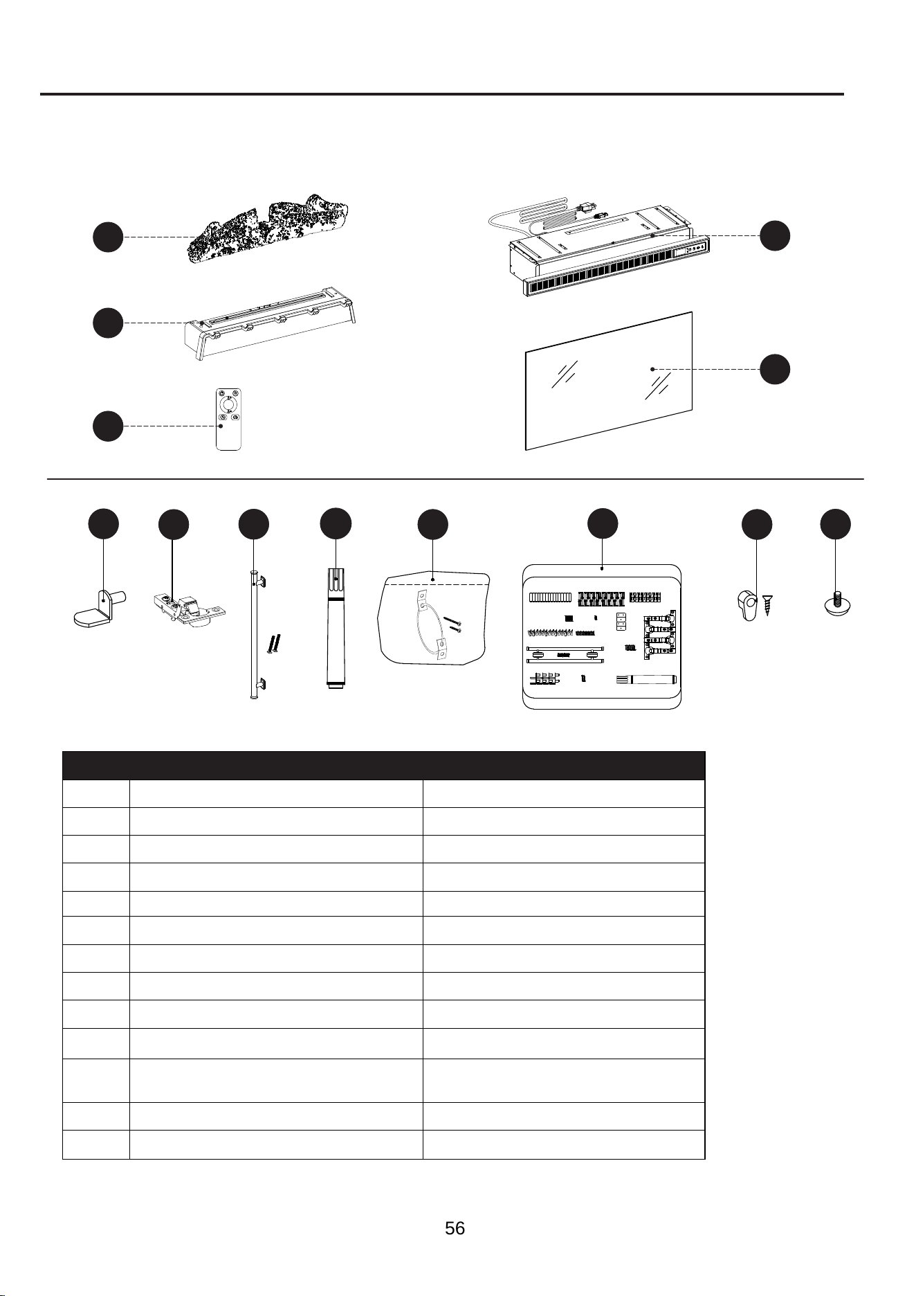
LISTA DE PIEZAS DE REPUESTO
Para obtener piezas de repuesto, llame a nuestro departamento de Servicio al Cliente al
866-439-9800, de lunes a domingo de 8 a.m. a 8 p.m., hora estándar del Este. También
puede ponerse en contacto con nosotros a través de [email protected].
PIEZA DESCRIPCIÓN N.º DE PIEZA
M
Leños para fuego
Fire Log 2
N
Rejilla de fuego
Fire Grate B
O
Control remoto
RC-HE85EL03
P
Calefactor negro
KDI-01-26
R
Frente de vidrio de la chimenea
PU-703x395-GLASS FRONT
FF
Soporte para estante
B1044
HH
Bisagra
PU-1010MFP HINGE
II
Tirador de puerta
PH-1010MFP CB DOOR PULL
MM
Aplicador de retoque
M-8505
NN
Aditamento de contención antivuelcos
ANTI-TIP HARDWARE SET
OO
Paquete de aditamentos KD
PH-1010MFP-58-26-501
HARDWARE PACK
PP
Sujetadores de vidrio
GLASS CLIPS
QQ
Nivelador
T-1007
Impreso en Vietnam
M
N
O
P
R
O
O
FF
O
HH
OII
O
NN
O
OO
O
PP
O
QQ
O
MM
56