
Warranty
LIMITED LIFETIME FOR MECHANICAL AND 1 YEAR FOR ELECTRONICAL WARRANTY
The retailer of this product, hereby warrants, subject to the conditions set forth below, that it will either repair or
replace, at its option, this product if it proves to be defective by reason of improper workmanship or materials
within the original purchaser’s lifetime. In order to obtain repairs or replacement under this limited warranty
you must bring this product to the retailer’s store in which you bought it.
Original purchaser: This limited warranty is limited to the original purchaser at retail of this product from retailer.
Except to the extent prohibited by applicable law, no other warranties, whether express or implied, including
the warranties of merchantability and tness for a particular purpose, shall apply to this product. Under no
circumstances shall retailer be liable for consequential or incidental damages in connection with this product. To
the extent retailer is prohibited by applicable law from excluding implied warranties, the duration of such implied
warranties which are not excludable shall be the original purchaser’s lifetime. Some states do not allow the
limitation on how long an implied warranty lasts, so the above limitation on the duration of implied warranties
which are not excludable, if any, may not apply to you. Some states do not allow the exclusion or limitation
of incidental or consequential damages, so the above limitation or exclusion of incidental or consequential
damages may not apply to you. Retailer neither assumes nor authorizes any representative or other person to
assume for it any obligation or liability other than such as is expressly set forth herein. This limited warranty
gives you specic legal rights, and you may also have other rights which vary from state to state.
Questions, problems, missing parts? Before returning to the store,
call Deant Customer Service
8 a.m. - 7 p.m., EST, Monday-Friday, 9 a.m. - 6 p.m., EST, Saturday
1-866-308-3976
HOMEDEPOT.COM
INSTALLATION GUIDE
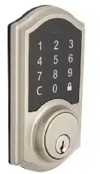
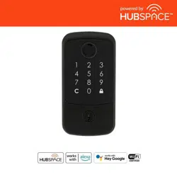
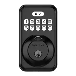
FINGERPRINT KEYPAD DEADBOLT
KPDKS02ADK02A
Rev. 1.0
THANK YOU
We appreciate the trust and confidence you have placed in Defiant through the purchase of this fingerprint keypad
deadbolt. We strive to continually create quality products designed to enhance your home. Visit us online to see our full
line of products available for your home improvement needs. Thank you for choosing Defiant!
1
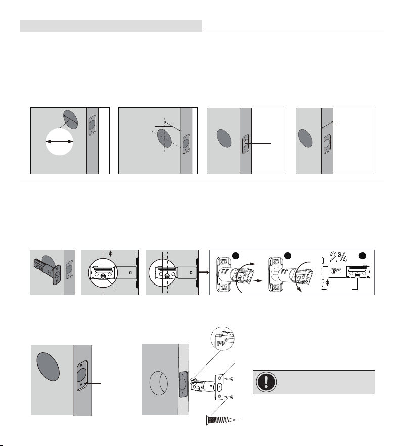
Preparing the door and checking dimensions
Measure to conrm that the hole in the door is 2-1/8 in. (54 mm).
Measure to conrm that the backset is either 2-3/8 in. or 2-3/4 in. (60 or 70 mm).
Measure to conrm that the hole in the door edge is 1 in. (25 mm).
Measure to conrm that the door is 1-3/8 in. to 2 in. (35 mm to 50 mm) thick.
2
Installing the latch and strike
Hold the latch (C) in front of the door hole, with the latch face ush against the door edge. No
adjustment is required if slotted hole is centered (backset 2-3/8 in.); Rotate and pull backwards the
latch to extend, then rotate it back as shown if slotted hole is not centered (backset 2-3/4in.).
2a. Installing latch and strike - door edge chiseled
Install the latch in door edge hole directly with latch screws (K) if your door edge is chiseled.
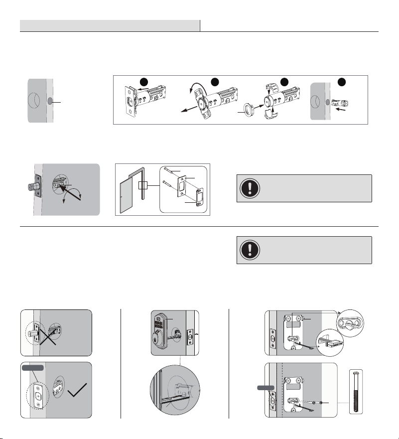
3
Installing exterior assembly
Route the power cable (M) below the latch.
Install exterior assembly (B) and send the power cable through the bottom horizontal slot in the
mounting plate (D).
Secure the mounting plate with the mounting screws (E).
4
Installing interior assembly
Remove the battery cover (G).
Connect the power cable (M) and ensure tight cable connection.
Rotate the thumb turn in vertical position and install the interior assembly (F).
Test the thumb turn for smooth rotation. If thumb turn doesn’t rotate, repeat last step, making sure
the thumb turn in vertical position.
Secure the interior assembly with the supplied screws (H).
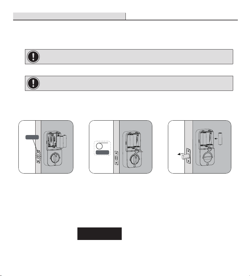
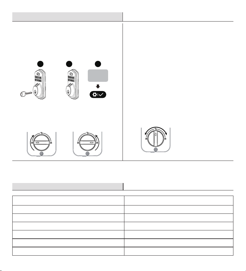
5
Detecting left/right hand door installation
Reset the lock to teach the lock the orientation of the door.
While the door is OPEN and UNLOCKED, load three AA batteries into the interior assembly.
Press and hold the Reset button on the interior assembly using the reset tool (O) included in package.
Load the last battery and keep holding the reset button for at least 3 seconds, until you hear the
sound of “beep”. The latch bolt will extend to learn the orientation of the door.
Safety Information
Read the precautions and instructions in this manual before installing and using this lock. Save this
manual for future reference.
Do not attempt to disassemble any internal components of the lockset. Doing so will void the limited
warranty.
Do not drop or hit the lockset. Too much shock may result in permanent damage.
Do not use pins or sharp objects to press the keypad and ngerprint sensor.
Always create a backup of information you wish to keep (Master Code, User Codes, etc.).
Promptly change the master code before operating this lockset.
Restrict access to your lock’s interior assembly and routinely check your settings to ensure they have
not been altered without your knowledge.
Care and Cleaning
Remove locks, or do not install locks, prior to painting your door.
Periodically clean with mild soap and a soft cloth only.
Do not use any abrasives or chemical products containing alcohol, benzene, or acids, and avoid using
sharp or abrasive objects to clean this lockset.
Do not allow any water or liquids into the lockset during installation.
This lockset is designed to provide the highest standard of product quality and performance. Care
should be taken to ensure a long-lasting nish. When cleaning is required use a soft, damp cloth.
Using lacquer thinner,caustic soaps,abrasive cleaners, or polishes could damage the coating and
result in tarnishing.
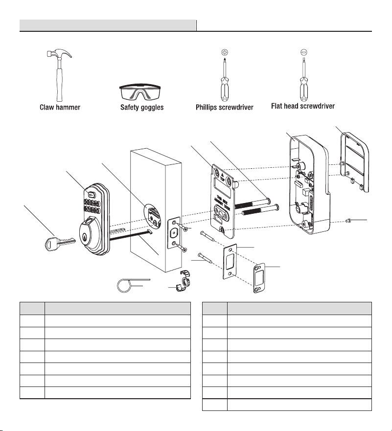
TOOLS REQUIRED
PACKAGE CONTENTS
Chiseled
Not
Chiseled
Insert a at head screwdriver into latch slot and rotate to test if deadbolt works smoothly.
Install strike (J) in the door frame with strike screws (L), and in order to maintain BHMA Grade 3,
you must install the reinforcement plate (I).
2b. Installing latch and strike - door edge not chiseled
U
se a at head screwdriver to remove rectangular face and rotate off part of the latch face, then install
drive-in collar (N) if your door edge is not chiseled. Then install latch in door with wood block and hammer.
1-3/8 in. to 2 in.
35 mm to 50 mm
2-3/8 in. or 2-3/4 in.
60 or 70 mm
Backset
2-1/8 in.
54 mm
1 in.
25 mm
Installation
Installation (continued) Installation (continued)
Installation (continued)
C
K
1 2 3 4
N
L
J
I
(optional)
latch slot
IMPORTANT: Make sure hole in
door frame is drilled a minimum of
1 in. (25.4 mm) deep.
IMPORTANT: Before installation,
make sure the latch is fully
retracted (in the unlocked position).
NOTE: Before beginning installation of product, make sure all parts are present. If any part is missing or
damaged, do not attempt to assemble, install or operate the product. Call the Customer Service Team at
1-866-308-3976 or visit www.homedepot.com.
IMPORTANT: Do not load batteries until lock is completely installed.
IMPORTANT: Lock knob will only rotate to the lock position in either the clockwise or
counterclockwise direction based on your door handing, not both.
IMPORTANT: This step is required and crucial for the lock to operate properly.
IMPORTANT: For best results, use new, non-rechargeable alkaline batteries only.
Unlocked
Parallel to the door edge.
Unlocked
B
M
D
E
Horizontal Torque Blade
F
D
M
G
H
Unlocked
Reset tool
O
See the User Guide for additional information.
WARNING: Do not use electric drill or electric screwdriver to tighten screws.
Pre-Installation
A
B
C
D
E
F
G
H
J
K
I
L
N
M
O
Part Description Part Description
A Backup Key HScrews
B Exterior Assembly I Reinforcement plate
C LatchJStrike
D Mounting Plate KLatch Screws (21 mm)
E Mounting Screws L Strike Screws (38 mm)
F Interior Assembly MPower Cable
G Battery Cover NDrive-in Collar
O Reset Tool
2-3/4 in.
70 mm
2-3/8 in.
60 mm
Slotted hole
1 32
IMPORTANT: Up arrow
needs to face up on latch.
Warranty
LIMITED LIFETIME FOR MECHANICAL AND 1 YEAR FOR ELECTRONICAL WARRANTY
The retailer of this product, hereby warrants, subject to the conditions set forth below, that it will either repair or
replace, at its option, this product if it proves to be defective by reason of improper workmanship or materials
within the original purchaser’s lifetime. In order to obtain repairs or replacement under this limited warranty
you must bring this product to the retailer’s store in which you bought it.
Original purchaser: This limited warranty is limited to the original purchaser at retail of this product from retailer.
Except to the extent prohibited by applicable law, no other warranties, whether express or implied, including
the warranties of merchantability and tness for a particular purpose, shall apply to this product. Under no
circumstances shall retailer be liable for consequential or incidental damages in connection with this product. To
the extent retailer is prohibited by applicable law from excluding implied warranties, the duration of such implied
warranties which are not excludable shall be the original purchaser’s lifetime. Some states do not allow the
limitation on how long an implied warranty lasts, so the above limitation on the duration of implied warranties
which are not excludable, if any, may not apply to you. Some states do not allow the exclusion or limitation
of incidental or consequential damages, so the above limitation or exclusion of incidental or consequential
damages may not apply to you. Retailer neither assumes nor authorizes any representative or other person to
assume for it any obligation or liability other than such as is expressly set forth herein. This limited warranty
gives you specic legal rights, and you may also have other rights which vary from state to state.
Questions, problems, missing parts? Before returning to the store,
call Deant Customer Service
8 a.m. - 7 p.m., EST, Monday-Friday, 9 a.m. - 6 p.m., EST, Saturday
1-866-308-3976
HOMEDEPOT.COM
INSTALLATION GUIDE
FINGERPRINT KEYPAD DEADBOLT
KPDKS02ADK02A
Rev. 1.0
THANK YOU
We appreciate the trust and confidence you have placed in Defiant through the purchase of this fingerprint keypad
deadbolt. We strive to continually create quality products designed to enhance your home. Visit us online to see our full
line of products available for your home improvement needs. Thank you for choosing Defiant!
1
Preparing the door and checking dimensions
Measure to conrm that the hole in the door is 2-1/8 in. (54 mm).
Measure to conrm that the backset is either 2-3/8 in. or 2-3/4 in. (60 or 70 mm).
Measure to conrm that the hole in the door edge is 1 in. (25 mm).
Measure to conrm that the door is 1-3/8 in. to 2 in. (35 mm to 50 mm) thick.
2
Installing the latch and strike
Hold the latch (C) in front of the door hole, with the latch face ush against the door edge. No
adjustment is required if slotted hole is centered (backset 2-3/8 in.); Rotate and pull backwards the
latch to extend, then rotate it back as shown if slotted hole is not centered (backset 2-3/4in.).
2a. Installing latch and strike - door edge chiseled
Install the latch in door edge hole directly with latch screws (K) if your door edge is chiseled.
3
Installing exterior assembly
Route the power cable (M) below the latch.
Install exterior assembly (B) and send the power cable through the bottom horizontal slot in the
mounting plate (D).
Secure the mounting plate with the mounting screws (E).
4
Installing interior assembly
Remove the battery cover (G).
Connect the power cable (M) and ensure tight cable connection.
Rotate the thumb turn in vertical position and install the interior assembly (F).
Test the thumb turn for smooth rotation. If thumb turn doesn’t rotate, repeat last step, making sure
the thumb turn in vertical position.
Secure the interior assembly with the supplied screws (H).
5
Detecting left/right hand door installation
Reset the lock to teach the lock the orientation of the door.
While the door is OPEN and UNLOCKED, load three AA batteries into the interior assembly.
Press and hold the Reset button on the interior assembly using the reset tool (O) included in package.
Load the last battery and keep holding the reset button for at least 3 seconds, until you hear the
sound of “beep”. The latch bolt will extend to learn the orientation of the door.
Safety Information
Read the precautions and instructions in this manual before installing and using this lock. Save this
manual for future reference.
Do not attempt to disassemble any internal components of the lockset. Doing so will void the limited
warranty.
Do not drop or hit the lockset. Too much shock may result in permanent damage.
Do not use pins or sharp objects to press the keypad and ngerprint sensor.
Always create a backup of information you wish to keep (Master Code, User Codes, etc.).
Promptly change the master code before operating this lockset.
Restrict access to your lock’s interior assembly and routinely check your settings to ensure they have
not been altered without your knowledge.
Care and Cleaning
Remove locks, or do not install locks, prior to painting your door.
Periodically clean with mild soap and a soft cloth only.
Do not use any abrasives or chemical products containing alcohol, benzene, or acids, and avoid using
sharp or abrasive objects to clean this lockset.
Do not allow any water or liquids into the lockset during installation.
This lockset is designed to provide the highest standard of product quality and performance. Care
should be taken to ensure a long-lasting nish. When cleaning is required use a soft, damp cloth.
Using lacquer thinner,caustic soaps,abrasive cleaners, or polishes could damage the coating and
result in tarnishing.
TOOLS REQUIRED
PACKAGE CONTENTS
Chiseled
Not
Chiseled
Insert a at head screwdriver into latch slot and rotate to test if deadbolt works smoothly.
Install strike (J) in the door frame with strike screws (L), and in order to maintain BHMA Grade 3,
you must install the reinforcement plate (I).
2b. Installing latch and strike - door edge not chiseled
U
se a at head screwdriver to remove rectangular face and rotate off part of the latch face, then install
drive-in collar (N) if your door edge is not chiseled. Then install latch in door with wood block and hammer.
1-3/8 in. to 2 in.
35 mm to 50 mm
2-3/8 in. or 2-3/4 in.
60 or 70 mm
Backset
2-1/8 in.
54 mm
1 in.
25 mm
Installation
Installation (continued) Installation (continued)
Installation (continued)
C
K
1 2 3 4
N
L
J
I
(optional)
latch slot
IMPORTANT: Make sure hole in
door frame is drilled a minimum of
1 in. (25.4 mm) deep.
IMPORTANT: Before installation,
make sure the latch is fully
retracted (in the unlocked position).
NOTE: Before beginning installation of product, make sure all parts are present. If any part is missing or
damaged, do not attempt to assemble, install or operate the product. Call the Customer Service Team at
1-866-308-3976 or visit www.homedepot.com.
IMPORTANT: Do not load batteries until lock is completely installed.
IMPORTANT: Lock knob will only rotate to the lock position in either the clockwise or
counterclockwise direction based on your door handing, not both.
IMPORTANT: This step is required and crucial for the lock to operate properly.
IMPORTANT: For best results, use new, non-rechargeable alkaline batteries only.
Unlocked
Parallel to the door edge.
Unlocked
B
M
D
E
Horizontal Torque Blade
F
D
M
G
H
Unlocked
Reset tool
O
See the User Guide for additional information.
WARNING: Do not use electric drill or electric screwdriver to tighten screws.
Pre-Installation
A
B
C
D
E
F
G
H
J
K
I
L
N
M
O
Part Description Part Description
A Backup Key HScrews
B Exterior Assembly I Reinforcement plate
C LatchJStrike
D Mounting Plate KLatch Screws (21 mm)
E Mounting Screws L Strike Screws (38 mm)
F Interior Assembly MPower Cable
G Battery Cover NDrive-in Collar
O Reset Tool
2-3/4 in.
70 mm
2-3/8 in.
60 mm
Slotted hole
1 32
IMPORTANT: Up arrow
needs to face up on latch.

This procedure will delete all User Codes associated with the lock.
Keep the door open and unlock.
Press and hold the Reset button. At the same time take out one battery and then place it back.
Keep holding the Reset button for at least 3 seconds, until you hear the sound of beep.
Quick Set Up
Programming Instructions
Master Code (4 to 10 digits): The default Master Code is 12345678. It is required that you change it
to a code of your own before programming.
User Code (4 to 10 digits): A total of 20 User Codes and 1 one-time User code can be programmed
and stored in the lock.
User ngerprint: 20 ngerprint can be programmed and stored in the lock.
Both master and user PIN codes do not support the following combination of numbers.
IMPORTANT: Do not load batteries until lock is completely installed.
123456789
987654321
222222222
5683
5683
91
91
5683
A. Forward number sequence
B. Backward number sequence
C. Repeat number sequence
D. If
Then Contain existing code sequence
and
Parts Illustrations
Item Specifications Remarks
Battery
(Use new, non-rechargeable alkaline
batteries only.)
AA alkaline battery x4 (Not included)
Lasts up to 9 month
(10 times unlock/lock per day)
Multifunction Button
Battery Cover
Reset Button
Thumb Turn
Keypad
Fingerprint Sensor
Cylinder
WARNING: The default Master Code is 12345678. It is required that you change it to a code of your own
before programming.
WARNING: The default Master Code is 12345678. It is required that you change it to a code of your own
before programming.
Wait for
Solid Green Lights
Wait for
Green Light Flash
Succeed
Green Light Flash
Wait for
Green Light Flash
Press
1
New Master PIN Code New XXXXXX PIN Code
Confirmation
Wait for
Green Light Flash
Succeed
Green Light Flash
Wait for
Green Light Flash
New User PIN Code
Succeed
Green Light Flash
Wait for
Green Light Flash
Press
2
Press
3
Change
Master
PIN
Code
Add
User
PIN
Code
Delete
User
PIN
Code
Succeed
Green Light Flash
Wait for
Green Light Flash
Wait for
Green Light Flash
New User PIN Code New User PIN Code
Enter New Duration
Time (10-99)
Succeed
Green Light Flash
Wait for
Green Light Flash
Press
9
Press
0
Add
One-Time
PIN
Code
Adjust
Auto
Re-lock
Duration
time
Wait for
Green Light Flash
Beeper Enabled
Green Light Flash
Green Light Flash
Beeper Disabled
Press
6
Enable/
Disable
Beeper
Green Light Flash
Enable Away Mode Succeed
Wait for
Green Light Flash
Wait for
Green Light Flash
Green Light Flash
Enable Auto Re-lock
Mode)
Green Light Flash
Disable Auto Re-lock (Manual
Press
7
Press
8
Away
Mode
Enable/
Disable
Auto
Re-lock
Wait for
Green Light Flash
Press
4
Add User
Fingerprint
Scan Fingerprint 8 Times
Each Time Succeed Along With a Short Beep
Succeed
Green Light Flash + A Long Beep
Wait for
Green Light Flash
Press
5
Delete User
Fingerprint
Succeed
Green Light Flash + A Long Beep
Scan Unwanted Fingerprint 1 Time
Master PIN Code
Press 2 Times
Press 1 Time Press 1 Time
New XXXXXX PIN Code
Confirmation
Press 1 Time
Press 1 Time Press 1 Time
Unwanted User PIN Code
Press 1 Time
Press
1
Press 1 Time
Press
1
Press 1 Time
Press
2
Press 1 Time
Press
2
Press 1 Time
Press 1 Time
Press 1 Time Press 1 Time
Press 1 Time
Master PIN Code
Press 2 Times
Press 1 Time
Wait for
Solid Green Lights
Master PIN Code
Press 2 Times
Press 1 Time
Master PIN Code
Press 2 Times
Press 1 Time
Wait for
Solid Green Lights
Wait for
Solid Green Lights
Master PIN Code
Press 2 Times
Press 1 Time
Wait for
Solid Green Lights
Master PIN Code
Press 2 Times
Press 1 Time
Wait for
Solid Green Lights
Master PIN Code
Press 2 Times
Press 1 Time
Wait for
Solid Green Lights
Master PIN Code
Press 2 Times
Press 1 Time
Wait for
Solid Green Lights
Master PIN Code
Press 2 Times
Press 1 Time
Wait for
Solid Green Lights
Master PIN Code
Press 2 Times
Press 1 Time
Wait for
Solid Green Lights
NOTE: When setting unsuccessful, the indicator light will ash red.
If no button is pressed for more than 10 seconds, the lock will exit programming mode.
Restore To Factory Default Settings
Quick Setup (continued)
Troubleshooting
Troubleshooting (continued)
83618 137192 14710
Real code
Random digits
21 137192 5486249
Real code
Random digits
5 137192 48
Real code
Random digits
96731286 137192 2
Real code
Random digits
MASTER CODE
Required for programming and feature settings. Master code can be used to unlock the door under away mode.
The default master code needs to be changed before programming. Property owner/manager should keep this
information condential.
AUTO LOCK
Automatically locks the deadbolt 30 seconds after unlocking.This feature is off by default.You can set the Auto
Lock time delay between 10 and 99 seconds.
WRONG ENTRY LIMIT
After 10 unsuccessful attempts at entering a invalid PIN code, the unit will shut down for 3 minutes.
SILENT MODE
The beep sounds when pressing keypad can be muted. But you will still hear low battery and system
alerts.
AWAY MODE
This is a security feature for you when you are leaving your home for vacation or long trip. Enabling
away mode will restrict all user codes and user ngerprints until master code is entered on keypad. If
the lock is unlocked by thumb turn or key, the lock will sound an alarm for 1 min. Entering master code
on keypad can disable alarm and away mode.
ONE TIME USER CODE
This code can only be used once and is automatically deleted when used.
UNLOCK WITH FAKE CODE
Any numbers can be entered before and after the real codes to prevent pincode from exposing to
strangers, but the limit included real code is 20 numbers.
Denitions
Operation
1
Unlocking the door from outside
Unlock by the mechanical key.
Unlock by the ngerprint.
Unlock by the Pin code.
2
Unlocking the door from inside
3
Locking the door from outside
Press any key on keypad for 2 seconds to
lock the door under manual mode.
The bolt will extend out automantically after
unlocking under auto re-lock mode.
4
Locking the door from inside
Rotate the thumb turn to lock position to
lock the door under manual mode.
Factory Default settings
Settings Factory Defaut
Master Code 12345678
Auto Lock Disabled
Silent Mode Disabled
Wrong Code Entry Limit 10 times
Shutdown Time (Wrong Entry 10 times) 3 mins
Away Mode Disabled
Rotate the thumb turn to unlock position.
Master/User
code
A B C
The device will be locked automatically
under auto-relock mode.
Problem Solution
The latch does not operate
correctly after installation.
Make sure the backset on the latch is set to the proper length. Refer to Installation Guide
Make sure prior to installation latch bolt is retracted and key is not in lockset when
installing the deadbolt. Refer to Installation Guide
Please restore to factory setting and enter the default Master Code to set up the
lock. Refer to User Guide
Feel a bump while turning
the thumb turn or the key?
Check if the length of mounting screws is correct.
Fail to set up the lock.
Please make sure the lock is installed correctly.
Please install fresh batteries and make sure the cable is connected correctly.
After installation, restore the lock to factory default to complete bolt direction setting.
Battery indicator keeps
ashing.
The batteries are getting low, please replace with four new batteries for the best
performance (alkaline batteries only).
Keypad not responding.
Make sure the batteries are installed properly.
The batteries are getting low if the battery indicator keeps ashing. Please replace
with four new batteries for the best performance (alkaline batteries only).
Make sure the cable is well-connected to the port, and was not damaged during
installation.
Please make sure the lock has been set up and complete the bolt direction determination.
Master Code can not be
changed.
Please refer to User Guide to restore factory settings and reprogram all codes.
What should I do if wrong
code was entered?
Press button once and continue to input code according to regular procedures.
I forgot my Master Codes.
Perform a reset in order to erase all passcodes. Once the reset is complete, all passcodes
will be erased and the Master code will return to the default master code 12345678.
Can not add a new User
Code.
Make sure the whole code entering process is completed within 10 seconds,
otherwise the unit will time out.
Make sure the Master Code has been entered correctly.
The new User Code will not be accepted when the capacity is full. Try to delete any
or some existing User Codes and then add new one(s) again. A User Code must be
at least 4 to 10 digits.
"Auto lock" does not
function.
The batteries are low on power if the battery indicator keeps ashing. Please
replace with four new batteries for the best performance (alkaline batteries only).
Please refer to User Guide to enable the Auto-Lock function.
Problem Solution
Lockset is not able to unlock
/ lock by keypad.
Make sure you have entered the correct User Code.
The battery is low if the battery indicator light keeps ashing. Please replace with
four new batteries.
Make sure the cable is rmly connected.
Check the cable for any damage that may have occurred during installation.
Make sure the batteries are properly installed. (Alkaline batteries only.)
Check the strike plate to make sure it is properly aligned and clear so the bolt can
freely move in the hole.
Lockset is unable to reset.
Please refer to User Guide to restore factory settings and reprogram all codes.
The battery is low if the battery indicator light keeps ashing. Please replace with
four new batteries.
How to operate the lockset
in darkness?
Press the lock button to activate the lockset back light.
The red indicator is still on
after setting is completed.
Check if you entered correct user codes.
Re-install the batteries.
The lockset locks when I
enter my code and unlocks
when I press the
.
Un-install the interior and exterior assemblies.
Before re-installation, please follow these guidelines:
Refer to Installation Guide
1) Make sure the bolt is in the retracted (unlocked) position.
2) Do not have any key in the cylinder durring installation.
3) Make sure the turn piece is inserted horizontally.
Reset the unit to factory settings and reprogram the Master Code and User Codes.
I cannot remove my key
unless it is in the locked
position.
Un-install the interior and exterior assemblies.
Before re-installation, please follow these guidelines:
Refer to Installation Guide
1) Make sure the bolt is in the retracted (unlocked) position.
2) Do not have any key in lock cylinder.
3) Make sure the turn piece is inserted horizontally.
Fingerprint can't unlock.
Make sure the ngerprint is registered and recognizable.
If the lock appears to be damaged or does not operate properly, please contact customer service for further assistance.
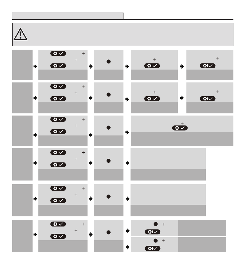
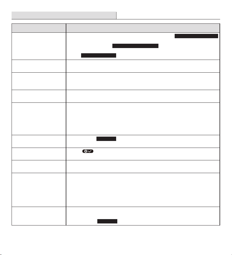
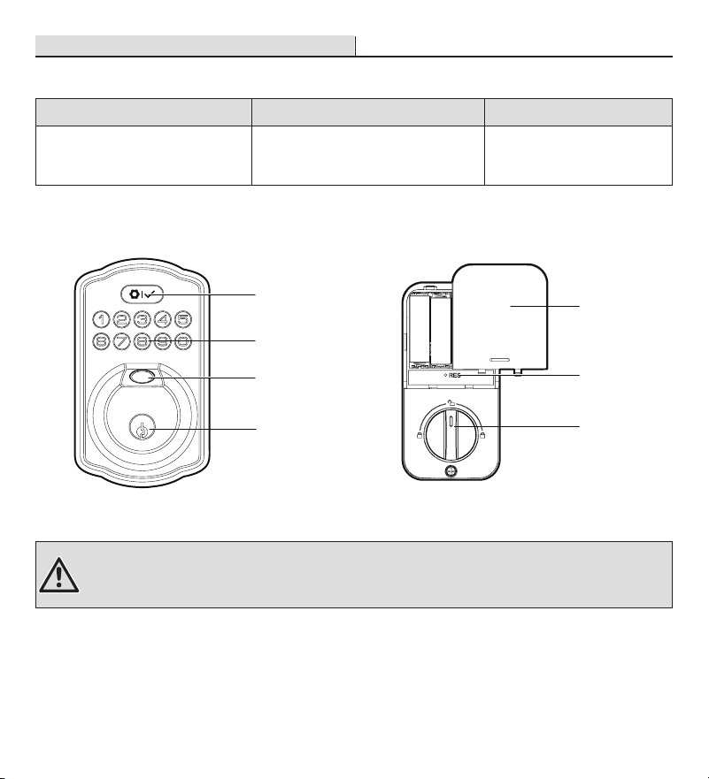
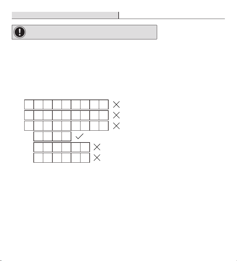
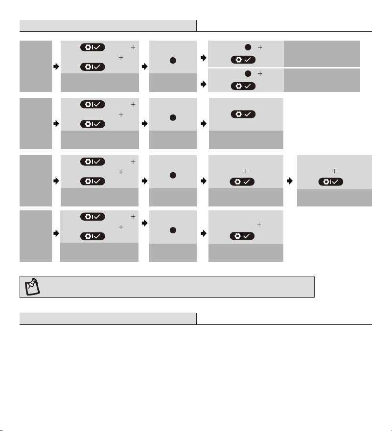
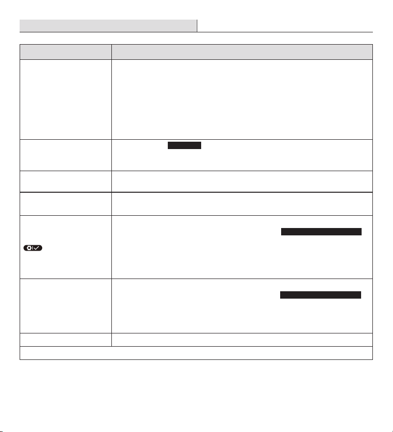
Warranty
LIMITED LIFETIME FOR MECHANICAL AND 1 YEAR FOR ELECTRONICAL WARRANTY
The retailer of this product, hereby warrants, subject to the conditions set forth below, that it will either repair or
replace, at its option, this product if it proves to be defective by reason of improper workmanship or materials
within the original purchaser’s lifetime. In order to obtain repairs or replacement under this limited warranty
you must bring this product to the retailer’s store in which you bought it.
Original purchaser: This limited warranty is limited to the original purchaser at retail of this product from retailer.
Except to the extent prohibited by applicable law, no other warranties, whether express or implied, including
the warranties of merchantability and tness for a particular purpose, shall apply to this product. Under no
circumstances shall retailer be liable for consequential or incidental damages in connection with this product. To
the extent retailer is prohibited by applicable law from excluding implied warranties, the duration of such implied
warranties which are not excludable shall be the original purchaser’s lifetime. Some states do not allow the
limitation on how long an implied warranty lasts, so the above limitation on the duration of implied warranties
which are not excludable, if any, may not apply to you. Some states do not allow the exclusion or limitation
of incidental or consequential damages, so the above limitation or exclusion of incidental or consequential
damages may not apply to you. Retailer neither assumes nor authorizes any representative or other person to
assume for it any obligation or liability other than such as is expressly set forth herein. This limited warranty
gives you specic legal rights, and you may also have other rights which vary from state to state.
Questions, problems, missing parts? Before returning to the store,
call Deant Customer Service
8 a.m. - 7 p.m., EST, Monday-Friday, 9 a.m. - 6 p.m., EST, Saturday
1-866-308-3976
HOMEDEPOT.COM
INSTALLATION GUIDE
FINGERPRINT KEYPAD DEADBOLT
KPDKS02ADK02A
Rev. 1.0
THANK YOU
We appreciate the trust and confidence you have placed in Defiant through the purchase of this fingerprint keypad
deadbolt. We strive to continually create quality products designed to enhance your home. Visit us online to see our full
line of products available for your home improvement needs. Thank you for choosing Defiant!
1
Preparing the door and checking dimensions
Measure to conrm that the hole in the door is 2-1/8 in. (54 mm).
Measure to conrm that the backset is either 2-3/8 in. or 2-3/4 in. (60 or 70 mm).
Measure to conrm that the hole in the door edge is 1 in. (25 mm).
Measure to conrm that the door is 1-3/8 in. to 2 in. (35 mm to 50 mm) thick.
2
Installing the latch and strike
Hold the latch (C) in front of the door hole, with the latch face ush against the door edge. No
adjustment is required if slotted hole is centered (backset 2-3/8 in.); Rotate and pull backwards the
latch to extend, then rotate it back as shown if slotted hole is not centered (backset 2-3/4in.).
2a. Installing latch and strike - door edge chiseled
Install the latch in door edge hole directly with latch screws (K) if your door edge is chiseled.
3
Installing exterior assembly
Route the power cable (M) below the latch.
Install exterior assembly (B) and send the power cable through the bottom horizontal slot in the
mounting plate (D).
Secure the mounting plate with the mounting screws (E).
4
Installing interior assembly
Remove the battery cover (G).
Connect the power cable (M) and ensure tight cable connection.
Rotate the thumb turn in vertical position and install the interior assembly (F).
Test the thumb turn for smooth rotation. If thumb turn doesn’t rotate, repeat last step, making sure
the thumb turn in vertical position.
Secure the interior assembly with the supplied screws (H).
5
Detecting left/right hand door installation
Reset the lock to teach the lock the orientation of the door.
While the door is OPEN and UNLOCKED, load three AA batteries into the interior assembly.
Press and hold the Reset button on the interior assembly using the reset tool (O) included in package.
Load the last battery and keep holding the reset button for at least 3 seconds, until you hear the
sound of “beep”. The latch bolt will extend to learn the orientation of the door.
Safety Information
Read the precautions and instructions in this manual before installing and using this lock. Save this
manual for future reference.
Do not attempt to disassemble any internal components of the lockset. Doing so will void the limited
warranty.
Do not drop or hit the lockset. Too much shock may result in permanent damage.
Do not use pins or sharp objects to press the keypad and ngerprint sensor.
Always create a backup of information you wish to keep (Master Code, User Codes, etc.).
Promptly change the master code before operating this lockset.
Restrict access to your lock’s interior assembly and routinely check your settings to ensure they have
not been altered without your knowledge.
Care and Cleaning
Remove locks, or do not install locks, prior to painting your door.
Periodically clean with mild soap and a soft cloth only.
Do not use any abrasives or chemical products containing alcohol, benzene, or acids, and avoid using
sharp or abrasive objects to clean this lockset.
Do not allow any water or liquids into the lockset during installation.
This lockset is designed to provide the highest standard of product quality and performance. Care
should be taken to ensure a long-lasting nish. When cleaning is required use a soft, damp cloth.
Using lacquer thinner,caustic soaps,abrasive cleaners, or polishes could damage the coating and
result in tarnishing.
TOOLS REQUIRED
PACKAGE CONTENTS
Chiseled
Not
Chiseled
Insert a at head screwdriver into latch slot and rotate to test if deadbolt works smoothly.
Install strike (J) in the door frame with strike screws (L), and in order to maintain BHMA Grade 3,
you must install the reinforcement plate (I).
2b. Installing latch and strike - door edge not chiseled
U
se a at head screwdriver to remove rectangular face and rotate off part of the latch face, then install
drive-in collar (N) if your door edge is not chiseled. Then install latch in door with wood block and hammer.
1-3/8 in. to 2 in.
35 mm to 50 mm
2-3/8 in. or 2-3/4 in.
60 or 70 mm
Backset
2-1/8 in.
54 mm
1 in.
25 mm
Installation
Installation (continued) Installation (continued)
Installation (continued)
C
K
1 2 3 4
N
L
J
I
(optional)
latch slot
IMPORTANT: Make sure hole in
door frame is drilled a minimum of
1 in. (25.4 mm) deep.
IMPORTANT: Before installation,
make sure the latch is fully
retracted (in the unlocked position).
NOTE: Before beginning installation of product, make sure all parts are present. If any part is missing or
damaged, do not attempt to assemble, install or operate the product. Call the Customer Service Team at
1-866-308-3976 or visit www.homedepot.com.
IMPORTANT: Do not load batteries until lock is completely installed.
IMPORTANT: Lock knob will only rotate to the lock position in either the clockwise or
counterclockwise direction based on your door handing, not both.
IMPORTANT: This step is required and crucial for the lock to operate properly.
IMPORTANT: For best results, use new, non-rechargeable alkaline batteries only.
Unlocked
Parallel to the door edge.
Unlocked
B
M
D
E
Horizontal Torque Blade
F
D
M
G
H
Unlocked
Reset tool
O
See the User Guide for additional information.
WARNING: Do not use electric drill or electric screwdriver to tighten screws.
Pre-Installation
A
B
C
D
E
F
G
H
J
K
I
L
N
M
O
Part Description Part Description
A Backup Key HScrews
B Exterior Assembly I Reinforcement plate
C LatchJStrike
D Mounting Plate KLatch Screws (21 mm)
E Mounting Screws L Strike Screws (38 mm)
F Interior Assembly MPower Cable
G Battery Cover NDrive-in Collar
O Reset Tool
2-3/4 in.
70 mm
2-3/8 in.
60 mm
Slotted hole
1 32
IMPORTANT: Up arrow
needs to face up on latch.
Garantía
GARANTÍA LIMITADA DE POR VIDA PARA ELEMENTOS MECÁNICOS Y GARANTÍA DE UN AÑO
PARA ELEMENTOS ELECTRÓNICOS
El distribuidor minorista de este producto garantiza por medio del presente documento, el cual está sujeto a
las condiciones establecidas a continuación, que reparará o reemplazará, a su discreción, este producto si se
comprueba que está defectuoso por motivos de mano de obra o materiales inadecuados dentro de la vida útil
del comprador original. Para obtener reparaciones o reemplazos cubiertos por esta garantía limitada, deberá
llevar este producto a la tienda del distribuidor minorista en el que lo compró.
Comprador original: Esta garantía limitada se limita al comprador original de este producto al proveedor
minorista.
Salvo en la medida en que lo prohíban las leyes aplicables, no se aplicará a este producto ninguna otra garantía,
ya sea expresa o implícita, incluidas las garantías de comerciabilidad e idoneidad para un n determinado. El
proveedor minorista no será responsable, bajo ninguna circunstancia, de los daños resultantes o incidentales
relacionados con este producto. En la medida en que las leyes aplicables prohíban al proveedor minorista
excluir las garantías implícitas, la duración de dichas garantías implícitas no excluibles será la del comprador
original. Algunos estados no permiten la limitación de la duración de una garantía implícita, de manera que
es posible que la limitación de la duración de las garantías implícitas no excluibles antedichas, en caso de
haberlas, no se apliquen su caso. Algunos estados no permiten la exclusión o la limitación de daños resultantes
o incidentales, de manera que es posible que la limitación o exclusión antedicha sobre daños resultantes o
incidentales no se aplique en su caso. El proveedor minorista no asume ni autoriza a ningún representante
u otra persona a asumir en su nombre ninguna obligación ni responsabilidad que no esté expresamente
establecida en el presente documento. Esta garantía limitada le otorga derechos legales especícos y también
puede tener otros derechos, que varían de estado a estado.
¿Tiene preguntas o problemas, o le faltan piezas? Antes de devolver a la tienda,
llame a Atención al Cliente de Deant
8 a. m. a 7:00 p. m., EST, y los sábados de 9:00 a. m. a 6:00 p. m., EST
1-866-308-3976
HOMEDEPOT.COM
GUÍA DE INSTALACIÓN
CERRADURA CON TECLADO Y
SENSOR DE HUELLA DACTILAR
KPDKS02ADK02A
Rev. 1.0
GRACIAS
Agradecemos la conanza que ha depositado en Deant con la compra de esta cerradura con teclado y sensor de
huella dactilar. Nos esforzamos continuamente para crear productos de calidad diseñados para mejorar su hogar.
Visítenos en línea para ver nuestra línea completa de productos disponibles para sus necesidades de mejoramiento del
hogar. ¡Gracias por elegir a Deant!
Aquí puede encontrar videos
sobre la instalación y
la programación:
1
Preparación de la puerta y comprobación de las dimensiones
Mida para conrmar que el oricio de la puerta tenga un tamaño de 2-1/8 pulgadas (54 mm).
Mida para conrmar que la distancia de retroceso sea de 2-3/8 o 2-3/4 pulgadas (60 o 70 mm).
Mida para conrmar que el oricio del borde de la puerta tenga un tamaño de 1 pulgada (25 mm).
Mida para conrmar que la puerta tenga un grosor de 1-3/8 a 2 pulgadas (35 mm a 50 mm).
2
Instalación del pestillo y la cerradura
Sostenga el pestillo (C) en frente del oricio de la puerta con la supercie del pestillo a ras del borde de
la puerta. Si el oricio ranurado está centrado, no será necesario realizar ajustes (distancia de retroceso
de 2-3/8 pulgadas o 4.12 cm); Gire y tire hacia atrás el pestillo para extenderlo, luego gírelo nuevamente
hacia su posición original, como se muestra, si el oricio ranurado no está centrado (distancia de
retroceso de 2-3/4 pulg.).
2a. Instalación del pestillo y la cerradura: puerta con borde cincelado
Si el borde de su puerta está cincelado, instale el pestillo en el oricio del borde de la puerta
directamente con los tornillos del pestillo (K).
3
Instalación del ensamblaje exterior
Pase el cable de alimentación (M) por debajo del pestillo.
Instale el ensamblaje exterior (B) y pase el cable de alimentación a través de la ranura horizontal
inferior de la placa de montaje (D).
Use los tornillos de montaje (E) para jar la placa de montaje.
4
Instalación del ensamblaje interior
Quite la cubierta de las pilas (G).
Conecte el cable de alimentación (M) y asegúrese de que esté conectado rmemente.
Gire el cerrojo manual, déjelo en posición vertical e instale el ensamblaje interior (F).
Pruebe si el cerrojo manual gira sin problemas. Si el cerrojo manual no gira, repita el último paso y
asegúrese de dejar el cerrojo manual en posición vertical.
Fije el ensamblaje interior con los tornillos suministrados (H).
5
Detección de la instalación de la puerta izquierda/derecha
Restablezca la cerradura para que registre la orientación de la puerta.
Con la puerta ABIERTA y DESBLOQUEADA, instale tres pilas AA en el interior del ensamblaje.
Mantenga presionado el botón de restablecimiento del ensamblaje interior utilizando la herramienta
de restablecimiento (O) incluida en el paquete.
Coloque la última pila y mantenga presionado el botón de restablecimiento durante al menos 3 segundos
hasta que escuche un pitido. El pasador se extenderá para registrar la orientación de la puerta.
Información de seguridad
Lea las precauciones y las instrucciones de este manual antes de instalar y usar esta cerradura. Guarde
este manual para consultarlo en el futuro.
No intente desensamblar ningún componente interno de la cerradura. Si lo hace, anulará la garantía
limitada.
No deje caer ni golpee la cerradura. Si sufre demasiados golpes puede dañarla permanentemente.
No use alleres ni objetos alados para presionar el teclado y el sensor de huella dactilar.
Siempre respalde la información que desee guardar (código maestro, códigos de usuario, etc.).
Cambie inmediatamente el código maestro antes de usar la cerradura.
Restrinja el acceso al ensamblaje interior de su cerradura y compruebe rutinariamente sus
conguraciones para asegurarse de que no hayan sido alteradas sin su conocimiento.
Cuidado y limpieza
Antes de pintar la puerta, retire la cerradura o píntela antes de su instalación.
Limpie periódicamente utilizando solamente jabón suave y un paño suave.
No use ningún producto químico o abrasivo que contenga alcohol, benceno o ácidos, y evite usar
objetos alados o abrasivos para limpiar esta cerradura.
No deje caer agua u otros líquidos en la cerradura durante su instalación.
Esta cerradura está diseñada para proporcionar un producto de los más altos estándares de calidad
y rendimiento. Se debe tener cuidado para garantizar un acabado duradero. Cuando sea necesario
limpiar, use un paño suave y húmedo.
El uso de disolventes de laca, jabones cáusticos, limpiadores abrasivos o pulidores puede dañar el
revestimiento y provocar deslustre.
HERRAMIENTAS NECESARIAS
CONTENIDO DEL PAQUETE
Cincelado
Sin cincelar
Inserte un destornillador plano en la ranura del pestillo y gire para probar si la cerradura funciona
correctamente.
Use los tornillos de la cerradura (L) para instalar la cerradura (J) en el marco de la puerta e instale la
placa de reforzamiento para mantener la clasicación de grado 3 de la BHMA.
2b. Instalación del pestillo y la cerradura: puerta con borde sin cincelar
Use un destornillador de cabeza plana para quitar la cara rectangular y gire hasta desmontar parte de
la cara del pestillo; a continuación, instale el collarín empotrable (N) si el borde de la puerta no está
cincelado. Luego, instale el pestillo en la puerta con un bloque de madera y un martillo.
1-3/8 pulg.
a 2 pulg.
35 mm a 50 mm
2-3/8 pulg. o 2-3/4 pulg.
60 o 70 mm
Distancia de
retroceso
Orificio de
2-1/8 de pulg.
54 mm
1 pulg.
25 mm
Instalación
Instalación (continuación) Instalación (continuación)
Instalación (continuación)
1 2 3 4
N
L
J
I
(Optativo)
Ranura
del pestillo
IMPORTANTE: Asegúrese de
que el oricio del marco de la
puerta tenga una perforación de
una profundidad mínima de 1
pulgada (25.4 mm).
IMPORTANTE: Antes de realizar la instalación,
asegúrese de que el pestillo esté completamente
retraído (en la posición de desbloqueo).
NOTA: Asegúrese de tener todas las piezas antes de comenzar la instalación del producto. Si falta alguna
pieza o está dañada, no intente armar, instalar ni usar el producto. Llame al equipo de Atención al Cliente al
1-866-308-3976 o visite www.homedepot.com.
IMPORTANTE: No coloque las pilas hasta que la cerradura esté completamente instalada.
IMPORTANTE: Este paso es necesario y crucial para que la cerradura funcione correctamente.
IMPORTANTE: Para obtener los mejores resultados, use solamente pilas alcalinas nuevas y no
recargables.
B
M
D
E
Desbloqueada
Desbloqueada
Paralelo al borde de la puerta
Clavija de apriete horizontal
F
D
M
G
H
Desbloqueada
Herramienta de
restablecimiento
O
Consulte la Guía del Usuario para obtener información adicional.
ADVERTENCIA: No apriete los tornillos con taladros ni destornilladores eléctricos.
Antes de la instalación
Pieza Descripción Pieza Descripción
A Llave de respaldo H Tornillos
B Ensamblaje exterior I Placa de refuerzo
C Pestillo J Cerradura
D Placa de montaje K Tornillos del pestillo (21 mm)
E Tornillos de montaje L Tornillos de la cerradura (38 mm)
F Ensamblaje interior M Cable de alimentación
G Cubierta de las pilas N Collarín empotrable
O Herramienta de restablecimiento
2-3/4 pulg.
70 mm
2-3/8 plug.
60 mm
orificio ranurado
1 32
Martillo de carpintero Gafas de seguridad Destornillador Phillips Destornillador de cabeza plana
A
B
C
D
E
F
G
H
J
K
I
L
N
M
O
IMPORTANTE: La echa
que apunta hacia arriba debe
mirar en esa dirección en el
pestillo.
IMPORTANTE: LLa perilla para trabar girará a la posición de cierre solo en el sentido de las
agujas del reloj, o en el sentido contrario a las agujas del reloj, según el sentido de apertura de la
puerta; no en ambos.
C
K
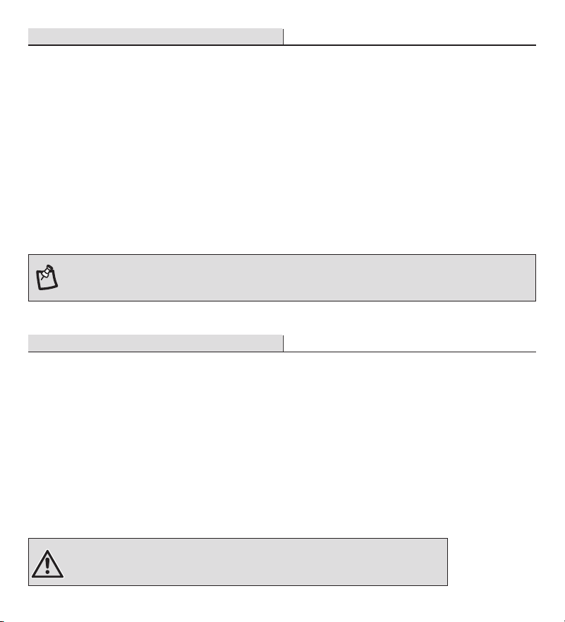
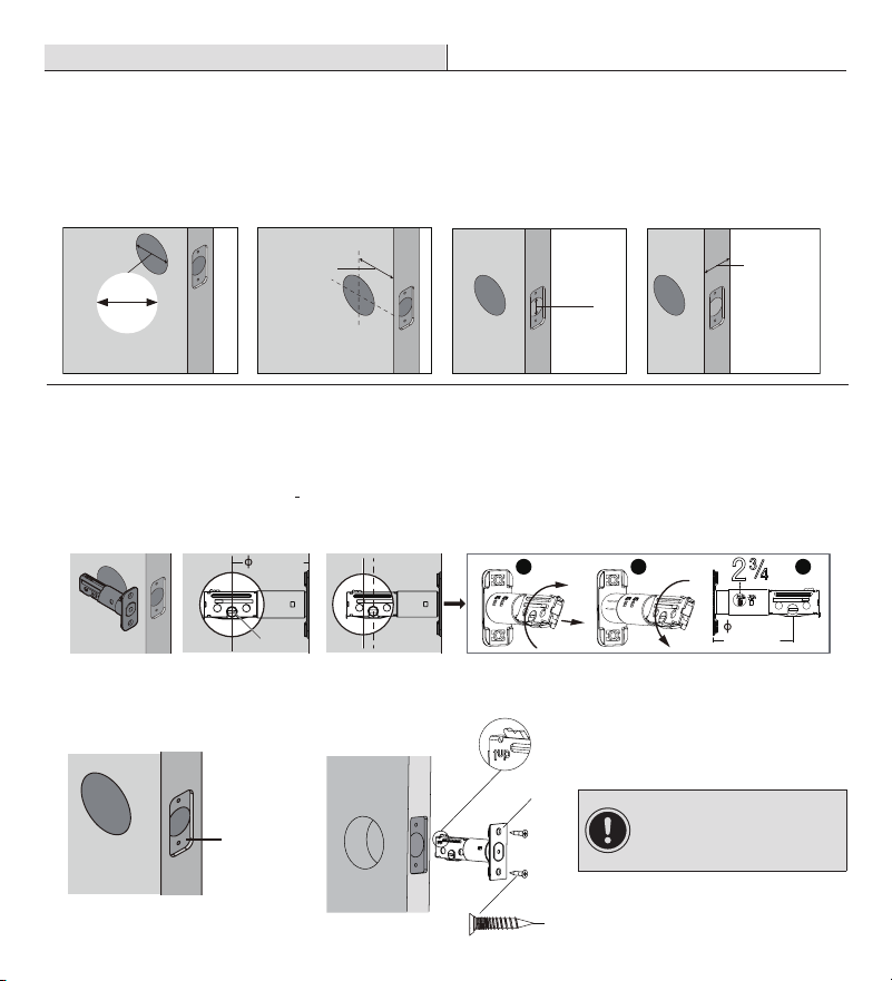
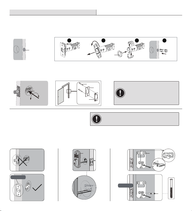
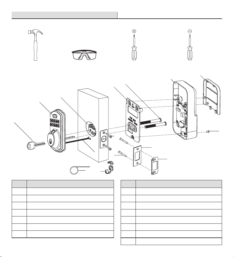
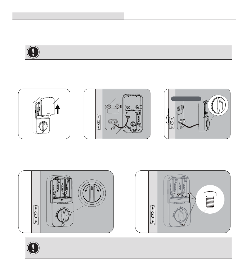
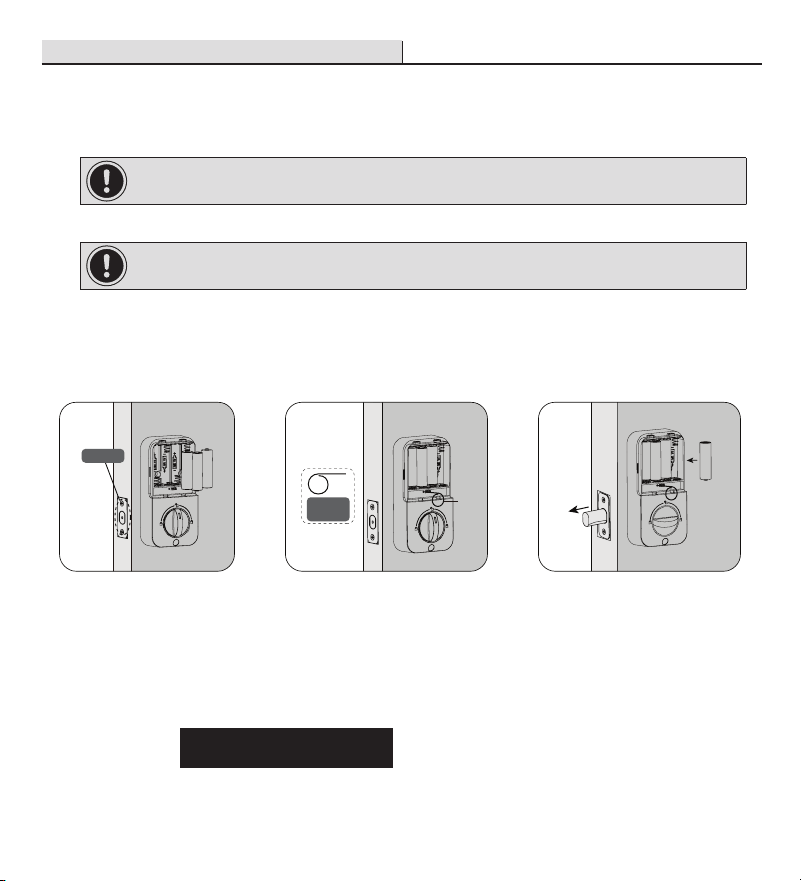
Este procedimiento eliminará todos los códigos de usuario asociados a la cerradura.
Mantenga la puerta abierta y desbloqueada.
Mantenga presionado el botón de restablecimiento. Al mismo tiempo, retire una pila y vuelva a
colocarla.
Siga manteniendo presionado el botón de restablecimiento durante al menos 3 segundos hasta
que escuche un pitido.
Conguración rápida
Instrucciones de programación
Código maestro (4 a 10 dígitos): el código maestro predeterminado es 12345678. Debe cambiarlo
por un código propio antes de realizar la programación.
Código de usuario (4 a 10 dígitos): Es posible programar y almacenar un total de 20 códigos de
usuario y 1 código de usuario de un solo uso en la cerradura.
Huella dactilar del usuario: Es posible programar y almacenar 20 huellas dactilares en la cerradura.
Tanto los códigos PIN maestro como los de usuario no admiten las siguientes combinaciones de
números.
IMPORTANTE: No coloque las pilas hasta que la cerradura esté
completamente instalada.
123456789
987654321
222222222
5683
5683
91
91
5683
A. Secuencia numérica ascendente
B. Secuencia numérica descendente
C. Secuencia numérica repetitiva
D. Si
Entonces Contiene la secuencia de códigos existente
y
Ilustraciones de las piezas
Artículo Especificaciones Observaciones
Pila
(use solo pilas alcalinas nuevas no
recargables)
4 pilas alcalinas AA (no incluidas)
Dura hasta 9 meses
(cuando se bloquea/desbloquea
10 veces por día)
Botón multifunción
Cubierta de las pilas
Botón Reset (Reiniciar)
Cerrojo manual
Teclado numérico
Sensor de huella dactilar
Cilindro
ADVERTENCIA: El código maestro predeterminado es 12345678. Debe cambiarlo por un código propio
antes de realizar la programación.
ADVERTENCIA: El código maestro predeterminado es 12345678. Debe cambiarlo por un código propio
antes de realizar la programación.
Cambiar
el código
PIN
maestro
Presione 2 Veces
Presione 1 Vez
Código PIN maestro
Espere a que la luz
cambie a verde fijo
Presione 2 Veces
Presione 1 Vez
Código PIN maestro
Espere a que la luz
cambie a verde fijo
Presione 2 Veces
Presione 1 Vez
Código PIN maestro
Espere a que la luz
cambie a verde fijo
Presione 2 Veces
Presione 1 Vez
Código PIN maestro
Espere a que la luz
cambie a verde fijo
Presione 2 Veces
Presione 1 Vez
Código PIN maestro
Espere a que la luz
cambie a verde fijo
Presione 2 Veces
Presione 1 Vez
Código PIN maestro
Espere a que la luz
cambie a verde fijo
Presione 2 Veces
Presione 1 Vez
Código PIN maestro
Espere a que la luz
cambie a verde fijo
Presione 2 Veces
Presione 1 Vez
Código PIN maestro
Espere a que la luz
cambie a verde fijo
Presione 2 Veces
Presione 1 Vez
Código PIN maestro
Espere a que la luz
cambie a verde fijo
Presione 2 Veces
Presione 1 Vez
Código PIN maestro
Espere a que la luz
cambie a verde fijo
Presione
1
Espere a que la luz
cambie a verde
parpadeante
Presione
2
Espere a que la luz
cambie a verde
parpadeante
Presione
3
Espere a que la luz
cambie a verde
parpadeante
Presione
4
Espere a que la luz
cambie a verde
parpadeante
Presione
5
Espere a que la luz
cambie a verde
parpadeante
Presione
6
Espere a que la luz
cambie a verde
parpadeante
Presione
7
Espere a que la luz
cambie a verde
parpadeante
Presione
8
Espere a que la luz
cambie a verde
parpadeante
Presione
9
Espere a que la luz
cambie a verde
parpadeante
Presione
0
Espere a que la luz
cambie a verde
parpadeante
Presione 1 Vez
Espere a que la luz cambie
a verde parpadeante
Nuevo código PIN maestro
Presione 1 Vez
Espere a que la luz cambie
a verde parpadeante
Nuevo código PIN de usuario
Confirmación del nuevo
código PIN XXXXXX
Presione 1 Vez
Parpadeo de luz verde al
realizarse correctamente
Confirmación del nuevo
código PIN XXXXXX
Presione 1 Vez
Presione 1 Vez
Presione
1
Presione 1 Vez
Presione
1
Presione 1 Vez
Presione
2
Presione 1 Vez
Presione
2
Presione 1 Vez
Presione 1 Vez
Presione 1 Vez Presione 1 Vez
Presione 1 Vez
Agregar
código PIN
de usuario
Eliminar
código PIN
de usuario
Agregar
código PIN
de un solo
uso
Ajuste del
tiempo de
duración
del
rebloqueo
automático
Activar/
desactivar
pitido
Modo
ausente
Activar/
desactivar
rebloqueo
automático
Agregar
huella
dactilar de
un usuario
Eliminar
huella
dactilar de
un usuario
Parpadeo de luz verde al
realizarse correctamente
Parpadeo de luz
verde al realizarse correctamente
Código PIN de usuario no deseado
Pitido activado
Parpadeo de luz verde
Parpadeo de luz verde
Pitido desactivado
Escanear la huella dactilar 8 veces
Cada vez que se realiza correctamente suena
un pitido corto
Correcto
Parpadeo de luz verde junto con un pitido largo
Correcto
Parpadeo de luz verde junto con un pitido largo
Escanear huella dactilar no deseada 1 vez
Correcto
Parpadeo de luz verde
Espere a que la luz cambie
a verde parpadeante
Nuevo código PIN de usuario Nuevo código PIN de usuario
Introduzca el nuevo tiempo
de duración (10-99)
Correcto
Parpadeo de luz verde
Parpadeo de luz verde
El modo ausente se activó
correctamente
Parpadeo de luz verde
Activar rebloqueo automático
Parpadeo de luz verde
Desactivación del rebloqueo automático
(modo manual)
NOTA: Cuando la conguración no se puede realizar correctamente, la luz indicadora parpadeará en rojo.
Si no se presiona ningún botón durante más de 10 segundos, la cerradura saldrá del modo de programación.
Restablecer a los valores predeterminados de fábrica
Conguración rápida (continuación)
Resolución de problemas
Resolución de problemas (continuación)
CÓDIGO MAESTRO
Necesario para la programación y la conguración de las funciones. El código maestro puede usarse para
desbloquear la puerta mientras está en modo ausente. El código maestro predeterminado debe cambiarse antes
de realizar la programación. El propietario/encargado debe mantener esta información como condencial.
BLOQUEO AUTOMÁTICO
Bloquea automáticamente la cerradura 30 segundos después de desbloquearla. Esta función viene desactivada
de forma predeterminada. Puede ajustar el tiempo de cuenta regresiva del bloqueo automático entre 10 y 99
segundos.
LÍMITE DE INTRODUCCIONES INCORRECTAS
Después de 10 introducciones incorrectas de un código PIN no válido, la unidad se apagará durante 3 minutos.
MODO SILENCIOSO
Es posible silenciar el pitido que suena al presionar el teclado. Sin embargo, podrá seguir escuchando
las alertas del sistema y de batería baja.
MODO AUSENTE
Esta es una función de seguridad ideal para usar cuando se va de la casa por vacaciones o un viaje
largo. Al activar el modo ausente, todas las huellas y códigos del usuario quedarán restringidos hasta
que se ingrese el código maestro en el teclado. Si la cerradura se destraba con el cerrojo manual o
llave, hará sonar una alarma durante 1 minuto. Se puede deshabilitar la alarma y el modo ausente
ingresando el código maestro en el teclado.
CÓDIGO DE USUARIO DE UN SOLO USO
Este código puede usarse solamente una vez y se elimina automáticamente cuando es utilizado.
DESBLOQUEO CON CÓDIGO FALSO
Es posible ingresar números cticios antes o después de los códigos reales, con el n de evitar mostrar
el código PIN a desconocidos; no obstante, el límite para el código real es 20 números.
Deniciones
83618 137192 14710
Código real
Dígitos al azar
21 137192 5486249
Código real
Dígitos al azar
5 137192 48
Código real
Dígitos al azar
96731286 137192 2
Código real
Dígitos al azar
Funcionamiento
1
Desbloqueo de la puerta desde el exterior
Desbloqueo con llave mecánica.
Desbloqueo con huella dactilar.
Desbloqueo con código PIN.
2
Desbloquee la puerta desde el lado
interior
3
Bloquee de la puerta desde el exterior
Presione cualquier tecla del teclado durante
2 segundos para bloquear la puerta en el
modo manual.
En el modo de rebloqueo automático, el
pestillo se extenderá automáticamente
después de quitar el seguro.
4
Bloqueo de la puerta desde el lado
interior
Conguración predeterminada de fábrica
Configuración Valores predeterminados de fábrica
Código maestro 12345678
Bloqueo automático Desactivado
Modo silencioso Desactivado
Límite de introducción de código incorrecto 10 veces
Tiempo de apagado (10 intentos fallidos) 3 minutos
Modo ausente Desactivado
Gire el cerrojo manual a la posición de
desbloqueo.
Código
maestro/de
usuario
CA B
Para bloquear la puerta en el modo manual,
gire el cerrojo manual a la posición de bloqueo.
El dispositivo se bloqueará automáticamente
en el modo de rebloqueo automático.
Problema Solución
El pestillo no funciona
correctamente después de
su instalación.
Asegúrese de que la distancia de retroceso del pestillo esté congurada a la longitud
correcta. Consulte la guía de instalación
Antes de la instalación, asegúrese de que el pasador esté retraído y de no dejar la
llave puesta en la cerradura durante la instalación. Consulte la guía de instalación
Restablezca la conguración de fábrica e introduzca el código maestro
predeterminado para congurar la cerradura. Consulte la guía del usuario
¿Siente un obstáculo al girar
cerrojo manual o la llave?
Compruebe si la longitud de los tornillos de montaje es la indicada.
Error en la conguración de
la cerradura.
Asegúrese de que la cerradura esté correctamente instalada.
Coloque pilas nuevas y asegúrese de que el cable esté conectado correctamente.
Después de la instalación, restaure los valores predeterminados de fábrica para nalizar
la conguración de la dirección del pestillo.
El indicador de las pilas
sigue parpadeando.
Las pilas se están agotando, sustitúyalas por cuatro pilas nuevas para obtener el mejor
rendimiento (use solo pilas alcalinas).
El teclado no funciona.
Asegúrese de que las pilas estén instaladas correctamente.
Si el indicador de las pilas sigue parpadeando, signica que las pilas se están
agotando. Sustitúyalas por cuatro pilas nuevas para obtener el mejor rendimiento
(use solo pilas alcalinas).
Asegúrese de que el cable esté bien conectado al puerto y de que no se dañe
durante la instalación.
Asegúrese de haber congurado la cerradura y de haber completado la determinación de
la dirección del pestillo.
No se puede cambiar el
código maestro.
Consulte la guía del usuario para restablecer las conguraciones de fábrica y volver a
programar todos los códigos.
¿Qué debo hacer si
se ingresó un código
incorrecto?
Presione el botón una vez e introduzca el código según los procedimientos
habituales.
Olvidé mis códigos maestros.
Realice un restablecimiento para eliminar todas las contraseñas. Una vez completado el
restablecimiento, se eliminarán todas las contraseñas y el código maestro volverá a ser
el código maestro predeterminado 12345678.
No puedo añadir un código
de usuario nuevo.
Asegúrese de completar todo el proceso de introducción del código antes de que
transcurran 10 segundos, de lo contrario la unidad se desconectará.
Asegúrese de haber ingresado correctamente el código maestro.
Si la capacidad de almacenamiento de códigos está llena, no se aceptará un
nuevo código de usuario. Intente eliminar algún código de usuario existente y
luego agregue nuevamente el código de usuario nuevo. El código de usuario debe
contener entre 4 y 10 dígitos.
El "autobloqueo" no
funciona.
Si el indicador de las pilas sigue parpadeando, signica que las pilas se están
agotando. Sustitúyalas por cuatro pilas nuevas para obtener el mejor rendimiento (use
solo pilas alcalinas).
Consulte la guía del usuario para activar la función de bloqueo automático.
Problema Solución
No se puede desbloquear/
bloquear la cerradura
mediante el teclado.
Asegúrese de haber introducido el código de usuario correcto.
Si la luz indicadora sigue parpadeando, signica que las pilas se están agotando.
Reemplace las pilas por cuatro pilas nuevas.
Asegúrese de que el cable esté conectado rmemente.
Compruebe que el cable no se haya dañado durante la instalación.
Asegúrese de que las pilas estén instaladas correctamente. (Use solo pilas
alcalinas).
Revise la placa de la cerradura para asegurarse de que esté correctamente alineada
y sin obstáculos para que el pestillo pueda moverse libremente en el oricio.
No se puede restablecer la
cerradura.
Consulte la guía del usuario para restablecer las conguraciones de fábrica y
volver a programar todos los códigos.
Si la luz indicadora sigue parpadeando, signica que las pilas se están agotando.
Reemplace las pilas por cuatro pilas nuevas.
¿Cómo puedo usar la
cerradura en la oscuridad?
Presione el botón de trabar para activar la luz trasera de la cerradura.
El indicador rojo sigue
encendido después de
completar la conguración.
Asegúrese de haber ingresado los códigos de usuario correctos.
Vuelva a instalar las pilas.
La cerradura se bloquea
cuando introduzco mi código
y se desbloquea cuando
presiono el botón
.
Desinstale el ensamblaje interior y el ensamblaje exterior.
Antes de la reinstalación, siga estas pautas:
Consulte la guía de instalación
1) Asegúrese de que el pestillo esté en la posición retraída (destrabada).
2) Durante la instalación no debe haber ninguna llave puesta en el cilindro.
3) Asegúrese de insertar el cerrojo manual de forma horizontal.
Restablezca la unidad a la conguración de fábrica y vuelva a programar el código
maestro y los códigos de usuario.
No puedo eliminar mi llave a
menos que se encuentre en
la posición de bloqueo.
Desinstale el ensamblaje interior y el ensamblaje exterior.
Antes de la reinstalación, siga estas pautas:
Consulte la guía de instalación
1) Asegúrese de que el pestillo esté en la posición retraída (destrabada).
2) No debe haber ninguna llave puesta en el cilindro de la cerradura.
3) Asegúrese de insertar el cerrojo manual de forma horizontal.
No se puede desbloquear
con huella dactilar.
Asegúrese de que la huella dactilar sea reconocible.
Si la cerradura parece estar dañada o no funciona correctamente, póngase en contacto con el servicio al cliente para
obtener más ayuda.
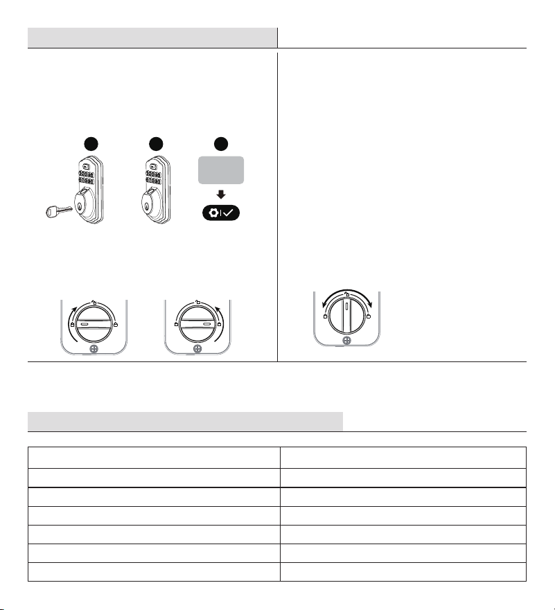
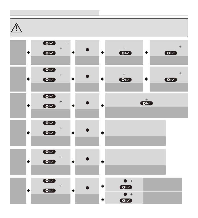
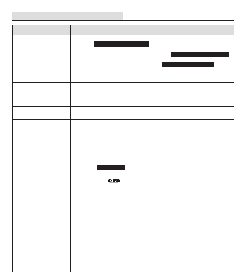
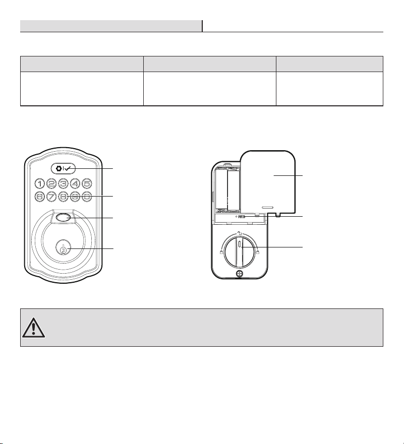
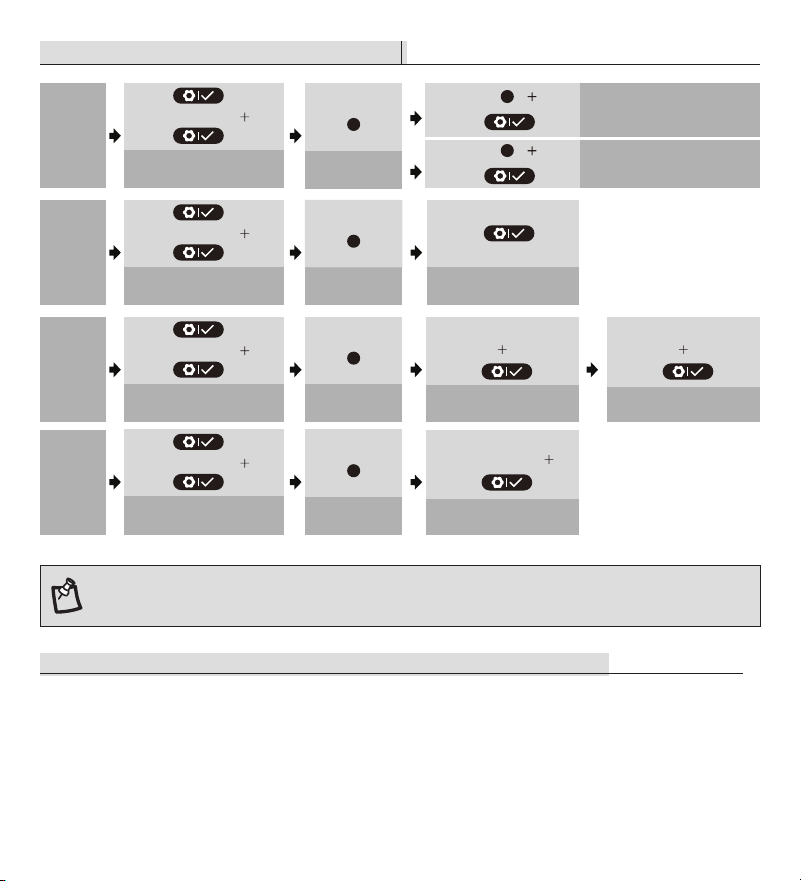
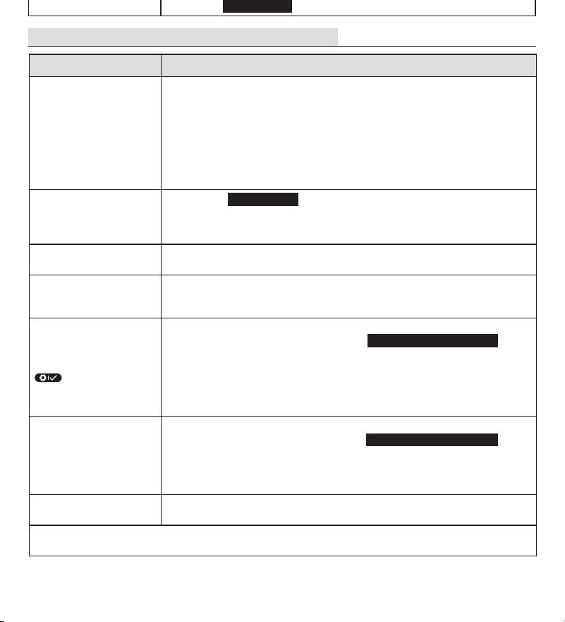
Garantía
GARANTÍA LIMITADA DE POR VIDA PARA ELEMENTOS MECÁNICOS Y GARANTÍA DE UN AÑO
PARA ELEMENTOS ELECTRÓNICOS
El distribuidor minorista de este producto garantiza por medio del presente documento, el cual está sujeto a
las condiciones establecidas a continuación, que reparará o reemplazará, a su discreción, este producto si se
comprueba que está defectuoso por motivos de mano de obra o materiales inadecuados dentro de la vida útil
del comprador original. Para obtener reparaciones o reemplazos cubiertos por esta garantía limitada, deberá
llevar este producto a la tienda del distribuidor minorista en el que lo compró.
Comprador original: Esta garantía limitada se limita al comprador original de este producto al proveedor
minorista.
Salvo en la medida en que lo prohíban las leyes aplicables, no se aplicará a este producto ninguna otra garantía,
ya sea expresa o implícita, incluidas las garantías de comerciabilidad e idoneidad para un n determinado. El
proveedor minorista no será responsable, bajo ninguna circunstancia, de los daños resultantes o incidentales
relacionados con este producto. En la medida en que las leyes aplicables prohíban al proveedor minorista
excluir las garantías implícitas, la duración de dichas garantías implícitas no excluibles será la del comprador
original. Algunos estados no permiten la limitación de la duración de una garantía implícita, de manera que
es posible que la limitación de la duración de las garantías implícitas no excluibles antedichas, en caso de
haberlas, no se apliquen su caso. Algunos estados no permiten la exclusión o la limitación de daños resultantes
o incidentales, de manera que es posible que la limitación o exclusión antedicha sobre daños resultantes o
incidentales no se aplique en su caso. El proveedor minorista no asume ni autoriza a ningún representante
u otra persona a asumir en su nombre ninguna obligación ni responsabilidad que no esté expresamente
establecida en el presente documento. Esta garantía limitada le otorga derechos legales especícos y también
puede tener otros derechos, que varían de estado a estado.
¿Tiene preguntas o problemas, o le faltan piezas? Antes de devolver a la tienda,
llame a Atención al Cliente de Deant
8 a. m. a 7:00 p. m., EST, y los sábados de 9:00 a. m. a 6:00 p. m., EST
1-866-308-3976
HOMEDEPOT.COM
GUÍA DE INSTALACIÓN
CERRADURA CON TECLADO Y
SENSOR DE HUELLA DACTILAR
KPDKS02ADK02A
Rev. 1.0
GRACIAS
Agradecemos la conanza que ha depositado en Deant con la compra de esta cerradura con teclado y sensor de
huella dactilar. Nos esforzamos continuamente para crear productos de calidad diseñados para mejorar su hogar.
Visítenos en línea para ver nuestra línea completa de productos disponibles para sus necesidades de mejoramiento del
hogar. ¡Gracias por elegir a Deant!
Aquí puede encontrar videos
sobre la instalación y
la programación:
1
Preparación de la puerta y comprobación de las dimensiones
Mida para conrmar que el oricio de la puerta tenga un tamaño de 2-1/8 pulgadas (54 mm).
Mida para conrmar que la distancia de retroceso sea de 2-3/8 o 2-3/4 pulgadas (60 o 70 mm).
Mida para conrmar que el oricio del borde de la puerta tenga un tamaño de 1 pulgada (25 mm).
Mida para conrmar que la puerta tenga un grosor de 1-3/8 a 2 pulgadas (35 mm a 50 mm).
2
Instalación del pestillo y la cerradura
Sostenga el pestillo (C) en frente del oricio de la puerta con la supercie del pestillo a ras del borde de
la puerta. Si el oricio ranurado está centrado, no será necesario realizar ajustes (distancia de retroceso
de 2-3/8 pulgadas o 4.12 cm); Gire y tire hacia atrás el pestillo para extenderlo, luego gírelo nuevamente
hacia su posición original, como se muestra, si el oricio ranurado no está centrado (distancia de
retroceso de 2-3/4 pulg.).
2a. Instalación del pestillo y la cerradura: puerta con borde cincelado
Si el borde de su puerta está cincelado, instale el pestillo en el oricio del borde de la puerta
directamente con los tornillos del pestillo (K).
3
Instalación del ensamblaje exterior
Pase el cable de alimentación (M) por debajo del pestillo.
Instale el ensamblaje exterior (B) y pase el cable de alimentación a través de la ranura horizontal
inferior de la placa de montaje (D).
Use los tornillos de montaje (E) para jar la placa de montaje.
4
Instalación del ensamblaje interior
Quite la cubierta de las pilas (G).
Conecte el cable de alimentación (M) y asegúrese de que esté conectado rmemente.
Gire el cerrojo manual, déjelo en posición vertical e instale el ensamblaje interior (F).
Pruebe si el cerrojo manual gira sin problemas. Si el cerrojo manual no gira, repita el último paso y
asegúrese de dejar el cerrojo manual en posición vertical.
Fije el ensamblaje interior con los tornillos suministrados (H).
5
Detección de la instalación de la puerta izquierda/derecha
Restablezca la cerradura para que registre la orientación de la puerta.
Con la puerta ABIERTA y DESBLOQUEADA, instale tres pilas AA en el interior del ensamblaje.
Mantenga presionado el botón de restablecimiento del ensamblaje interior utilizando la herramienta
de restablecimiento (O) incluida en el paquete.
Coloque la última pila y mantenga presionado el botón de restablecimiento durante al menos 3 segundos
hasta que escuche un pitido. El pasador se extenderá para registrar la orientación de la puerta.
Información de seguridad
Lea las precauciones y las instrucciones de este manual antes de instalar y usar esta cerradura. Guarde
este manual para consultarlo en el futuro.
No intente desensamblar ningún componente interno de la cerradura. Si lo hace, anulará la garantía
limitada.
No deje caer ni golpee la cerradura. Si sufre demasiados golpes puede dañarla permanentemente.
No use alleres ni objetos alados para presionar el teclado y el sensor de huella dactilar.
Siempre respalde la información que desee guardar (código maestro, códigos de usuario, etc.).
Cambie inmediatamente el código maestro antes de usar la cerradura.
Restrinja el acceso al ensamblaje interior de su cerradura y compruebe rutinariamente sus
conguraciones para asegurarse de que no hayan sido alteradas sin su conocimiento.
Cuidado y limpieza
Antes de pintar la puerta, retire la cerradura o píntela antes de su instalación.
Limpie periódicamente utilizando solamente jabón suave y un paño suave.
No use ningún producto químico o abrasivo que contenga alcohol, benceno o ácidos, y evite usar
objetos alados o abrasivos para limpiar esta cerradura.
No deje caer agua u otros líquidos en la cerradura durante su instalación.
Esta cerradura está diseñada para proporcionar un producto de los más altos estándares de calidad
y rendimiento. Se debe tener cuidado para garantizar un acabado duradero. Cuando sea necesario
limpiar, use un paño suave y húmedo.
El uso de disolventes de laca, jabones cáusticos, limpiadores abrasivos o pulidores puede dañar el
revestimiento y provocar deslustre.
HERRAMIENTAS NECESARIAS
CONTENIDO DEL PAQUETE
Cincelado
Sin cincelar
Inserte un destornillador plano en la ranura del pestillo y gire para probar si la cerradura funciona
correctamente.
Use los tornillos de la cerradura (L) para instalar la cerradura (J) en el marco de la puerta e instale la
placa de reforzamiento para mantener la clasicación de grado 3 de la BHMA.
2b. Instalación del pestillo y la cerradura: puerta con borde sin cincelar
Use un destornillador de cabeza plana para quitar la cara rectangular y gire hasta desmontar parte de
la cara del pestillo; a continuación, instale el collarín empotrable (N) si el borde de la puerta no está
cincelado. Luego, instale el pestillo en la puerta con un bloque de madera y un martillo.
1-3/8 pulg.
a 2 pulg.
35 mm a 50 mm
2-3/8 pulg. o 2-3/4 pulg.
60 o 70 mm
Distancia de
retroceso
Orificio de
2-1/8 de pulg.
54 mm
1 pulg.
25 mm
Instalación
Instalación (continuación) Instalación (continuación)
Instalación (continuación)
1 2 3 4
N
L
J
I
(Optativo)
Ranura
del pestillo
IMPORTANTE: Asegúrese de
que el oricio del marco de la
puerta tenga una perforación de
una profundidad mínima de 1
pulgada (25.4 mm).
IMPORTANTE: Antes de realizar la instalación,
asegúrese de que el pestillo esté completamente
retraído (en la posición de desbloqueo).
NOTA: Asegúrese de tener todas las piezas antes de comenzar la instalación del producto. Si falta alguna
pieza o está dañada, no intente armar, instalar ni usar el producto. Llame al equipo de Atención al Cliente al
1-866-308-3976 o visite www.homedepot.com.
IMPORTANTE: No coloque las pilas hasta que la cerradura esté completamente instalada.
IMPORTANTE: Este paso es necesario y crucial para que la cerradura funcione correctamente.
IMPORTANTE: Para obtener los mejores resultados, use solamente pilas alcalinas nuevas y no
recargables.
B
M
D
E
Desbloqueada
Desbloqueada
Paralelo al borde de la puerta
Clavija de apriete horizontal
F
D
M
G
H
Desbloqueada
Herramienta de
restablecimiento
O
Consulte la Guía del Usuario para obtener información adicional.
ADVERTENCIA: No apriete los tornillos con taladros ni destornilladores eléctricos.
Antes de la instalación
Pieza Descripción Pieza Descripción
A Llave de respaldo H Tornillos
B Ensamblaje exterior I Placa de refuerzo
C Pestillo J Cerradura
D Placa de montaje K Tornillos del pestillo (21 mm)
E Tornillos de montaje L Tornillos de la cerradura (38 mm)
F Ensamblaje interior M Cable de alimentación
G Cubierta de las pilas N Collarín empotrable
O Herramienta de restablecimiento
2-3/4 pulg.
70 mm
2-3/8 plug.
60 mm
orificio ranurado
1 32
Martillo de carpintero Gafas de seguridad Destornillador Phillips Destornillador de cabeza plana
A
B
C
D
E
F
G
H
J
K
I
L
N
M
O
IMPORTANTE: La echa
que apunta hacia arriba debe
mirar en esa dirección en el
pestillo.
IMPORTANTE: LLa perilla para trabar girará a la posición de cierre solo en el sentido de las
agujas del reloj, o en el sentido contrario a las agujas del reloj, según el sentido de apertura de la
puerta; no en ambos.
C
K