NOTE:
Before beginning installation of product, make sure all parts are present. If any part is missing or damaged,
do not attempt to assemble, install or operate the product. Call the Customer Service Team or visit
www.homedepot.com.
WARNING:
If the door needs to be drilled, please be familiar with how to use a drill safely and understand all of the
door preparation steps before proceeding.
Optional Optional Optional Optional Optional Optional
G32-KPDAH12A-XQ
Rev. 22/07-01
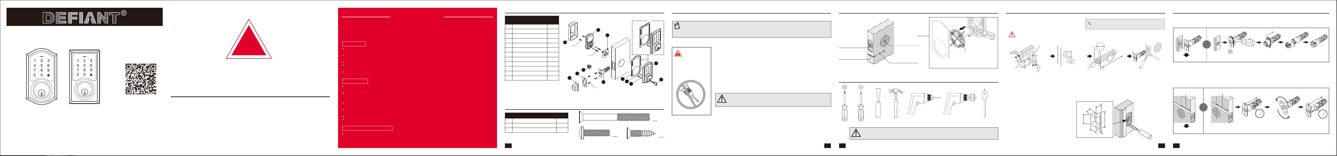
Hardware Contents (Actual Size)
Package Contents List
Safety Information Before Proceeding
Step 1: Drill Door For New Installation Step 2: Install the latch and strike
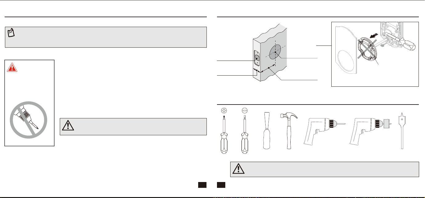
Tools Required
I Dust Box
J Key
K Drive-in Collar (Optional)
L Exterior Gasket
E Interior Assembly
1
F Battery Cover
1
G Latch
1
H Strike Plate
1
2
1
1
1
A Exterior Assembly
B Power Cable
C Torque blade
D Mounting Plate
1
1
Part
Description
Quantity
1
1
AA 1-13/16" (46 mm) Mounting Bolt
BB 13/16" (20 mm) Screw
CC 3/4" (19 mm) Wood Screw
2
2
Part
Description
Quantity
4
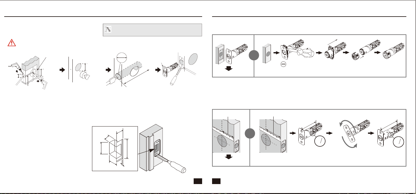
Cut out TEMPLATE and use to mark the door,
drill holes, and chisel out the mortise.
Drill from both sides of the door to prevent wood splitting.
1"
(25 mm)
2-1/8"
(54 mm)
1-1/2"
(38 mm)
or
2-1/8"
(54 mm)
1-1/2"
(38 mm)
or
Backset
Centerline
1”
(25 mm)
Outline
Chisel
5/32” (4 mm)
deep
Faceplate
c
b
f
e
a
d
Prepare the door jamb – use the strike plate as a template to drill the latch and screw holes and chisel out the
mortise. The strike plate must fit flush with the surface of the door jamb.
Door jamb hole dimension
Strike dimentions
b. 1-9/64"(29 mm)
d. 5/32"(4 mm)
e. 2-1/4"(57 mm)
f. 1"(25 mm)
a. 1-3/16"(30 mm)
c. 7/8"(22 mm)
For 2-3/8” (60 mm) backset: 3-7/16” (87 mm)
or
For 2-3/4” (70 mm) backset: 3-13/16” (97 mm)
Depth of latch hole
Check Dimensions
1-3/8” - 2”
(35 mm - 51 mm)
2-3/8” (60 mm)
OR
2-3/4” (70 mm)
1-1/2” (38 mm)
OR
2-1/8” (54 mm)
1” (25 mm)
NOTE:
If your door already has holes, skip to
Step 2
For installation into 1-1/2”(38 mm) bore hole,
simply pry the adapter collar off with a screwdriver.
Choose faceplate
Set the latch backset
Edge of door
Flat head screwdriver
Edge of door
Drive-in collar
Your latch is set for 2-3/8” backset. It can be adjusted if needed to 2-3/4” (skip this if your door has a 2-3/8” backset).
Proceed to next step.
Proceed to next step.
2
8
3
2
8
3
2
-
3
/
8
”
(
6
0
m
m
)
180º
2
8
3
2
4
3
2
8
3
2
4
3
2
-
3
/
4
”
(
7
0
m
m
)
2-3/4’’ (70 mm)2-3/8’’ (60 mm)
CARE and MAINTENANCE:
The following instructions should be followed to properly protect and maintain
your lockset:
Read the precautions and instructions in this manual before installing and using this lock.
Save this manual for future reference.
A. Remove locks, or do not install locks, prior to painting your door.
B. Periodically clean with mild soap and a soft cloth only.
C. Do not use any abrasives or chemical products containing alcohol, benzene, acids, and
avoid using sharp or abrasive objects to clean this lockset.
D. Do not allow any water or liquids into the lockset during installation.
A. Do not attempt to disassemble any internal components of the lockset. Doing so will
void the limited warranty.
B. Do not drop or hit the lockset. Too much shock may result in permanent damage.
C. Do not use pins or sharp objects to press the keypad.
D. Always create a backup of information you wish to keep (Master Code, User Codes,etc.)
E. Promptly change the Master Code before operating this lockset.
F. Restrict access to your lock’s interior assembly and routinely check your settings to
ensure they have not been altered without your knowledge.
Do not use electric
drill or electric
screwdriver to
tighten screws.
01
02 03
04 05
OR
OR
Questions, problems, missing parts?
Before returning to the store, call Deant Customer Service
TOLL FREE HELP LINE 1-877-663-5625
HOMEDEPOT.COM
08:30 a.m.-05:30 p.m., EST, Monday - Friday
INSTALLATION GUIDE
WARRANTY
LIMITED LIFETIME MECHANICAL AND 1 YEAR ELECTRONIC WARRANTY
The retailer of this product, hereby warrants, subject to the conditions set forth below, that it will either repair or replace, at its option,
this product if it proves to be defective by reason of improper workmanship or materials within the original purchaser's limited time. In
order to obtain repairs or replacement under this limited warranty you must bring this product to the retailer's store in which you
bought it.
Original purchaser: This limited warranty is limited to the original purchaser at retail of this product from retailer.
Except to the extent prohibited by applicable law, no other warranties, whether express or implied, including the warranties of
merchantability and tness for a particular purpose, shall apply to this product. Under no circumstances shall retailer be liable for
consequential or incidental damages in connection with this product. To the extent retailer is prohibited by applicable law from
excluding implied warranties, the duration of such implied warranties which are not excludable shall be the original purchaser's
lifetime. Some states do not allow the limitation on how long an implied warranty lasts, so the above limitation on the duration of
implied warranties which are not excludable, if any, may not apply to you. Some states do not allow the exclusion or limitation of
incidental or consequential damages, so the above limitation or exclusion of incidental or consequential damages may not apply to you.
Retailer neither assumes not authorizes any representative or other person to assume for it any obligation or liability other than such as
is expressly set forth herein. This limited warranty gives you specic legal rights, and you may also have other rights which vary from
state to state.
Contents in this package are NOT interchangeable with other units.
Please contact customer service for more information.
!
IMPORTANT NOTICE
Please Read This Notice before Installing, Using, and Servicing the Product
Please contact your local service provider prior to the installation as your door preparation may be different from
the standard the product conforms to.
Please perform the bolt direction determination immediately after the product is successfully mounted to the
door. You may refer to Page 10 for more details.
Please change the master code (programming code) to prevent unauthorized individuals from gaining access.
Any removal or replacement of parts in installation is NOT recommended and may invalidate the warranty of the
product.
Not to be used on an Emergency Exit.
The product is designed and manufactured for providing security. Please read carefully and follow the
instructions given below. Lack of proper working knowledge or improper use could cause unexpected
damage or loss to personal or commercial belongings.
ALWAYS use authentic alkaline batteries. It is the user’s responsibility for damage caused by using
unauthentic batteries.
The product is made of mechanical and electronic components, which may be sensitive towards water, physical
impact, and electric shock. Using the product with care prevents unexpected malfunction and optimizes the
product life span.
DO NOT disassemble the product without advice from qualified service provider. Unauthorized disassembly will
void the product warranty.
Please refer to TROUBLESHOOTING page if any problem occurs, or contact your local service provider for
professional instructions.
Remove all batteries from the lock at the same time and replace them with new batteries of the same size and type.
Preserve battery and lock life by removing the batteries when the lock is not being used for more than 3 months.
ALWAYS refer to user’s manual or seek advice from your local service provider on cleaning, moving, or
maintaining the product.
The information in this notice is subject to change without notice.
Installation
Product Use
Service and Maintenance
BB
AA
CC
https://bit.ly/3rknTD9
SCAN FOR
INSTALLATION
F
E
I
H
K
J
A
C
L
D
G
B
OR
CC
AA
BB
Adapter collar
NOTE:
Before beginning installation of product, make sure all parts are present. If any part is missing or damaged,
do not attempt to assemble, install or operate the product. Call the Customer Service Team or visit
www.homedepot.com.
WARNING:
If the door needs to be drilled, please be familiar with how to use a drill safely and understand all of the
door preparation steps before proceeding.
Optional Optional Optional Optional Optional Optional
G32-KPDAH12A-XQ
Rev. 22/07-01
Hardware Contents (Actual Size)
Package Contents List
Safety Information Before Proceeding
Step 1: Drill Door For New Installation Step 2: Install the latch and strike
Tools Required
I Dust Box
J Key
K Drive-in Collar (Optional)
L Exterior Gasket
E Interior Assembly
1
F Battery Cover
1
G Latch
1
H Strike Plate
1
2
1
1
1
A Exterior Assembly
B Power Cable
C Torque blade
D Mounting Plate
1
1
Part
Description
Quantity
1
1
AA 1-13/16" (46 mm) Mounting Bolt
BB 13/16" (20 mm) Screw
CC 3/4" (19 mm) Wood Screw
2
2
Part
Description
Quantity
4
Cut out TEMPLATE and use to mark the door,
drill holes, and chisel out the mortise.
Drill from both sides of the door to prevent wood splitting.
1"
(25 mm)
2-1/8"
(54 mm)
1-1/2"
(38 mm)
or
2-1/8"
(54 mm)
1-1/2"
(38 mm)
or
Backset
Centerline
1”
(25 mm)
Outline
Chisel
5/32” (4 mm)
deep
Faceplate
c
b
f
e
a
d
Prepare the door jamb – use the strike plate as a template to drill the latch and screw holes and chisel out the
mortise. The strike plate must fit flush with the surface of the door jamb.
Door jamb hole dimension
Strike dimentions
b. 1-9/64"(29 mm)
d. 5/32"(4 mm)
e. 2-1/4"(57 mm)
f. 1"(25 mm)
a. 1-3/16"(30 mm)
c. 7/8"(22 mm)
For 2-3/8” (60 mm) backset: 3-7/16” (87 mm)
or
For 2-3/4” (70 mm) backset: 3-13/16” (97 mm)
Depth of latch hole
Check Dimensions
1-3/8” - 2”
(35 mm - 51 mm)
2-3/8” (60 mm)
OR
2-3/4” (70 mm)
1-1/2” (38 mm)
OR
2-1/8” (54 mm)
1” (25 mm)
NOTE:
If your door already has holes, skip to
Step 2
For installation into 1-1/2”(38 mm) bore hole,
simply pry the adapter collar off with a screwdriver.
Choose faceplate
Set the latch backset
Edge of door
Flat head screwdriver
Edge of door
Drive-in collar
Your latch is set for 2-3/8” backset. It can be adjusted if needed to 2-3/4” (skip this if your door has a 2-3/8” backset).
Proceed to next step.
Proceed to next step.
2
8
3
2
8
3
2
-
3
/
8
”
(
6
0
m
m
)
180º
2
8
3
2
4
3
2
8
3
2
4
3
2
-
3
/
4
”
(
7
0
m
m
)
2-3/4’’ (70 mm)2-3/8’’ (60 mm)
CARE and MAINTENANCE:
The following instructions should be followed to properly protect and maintain
your lockset:
Read the precautions and instructions in this manual before installing and using this lock.
Save this manual for future reference.
A. Remove locks, or do not install locks, prior to painting your door.
B. Periodically clean with mild soap and a soft cloth only.
C. Do not use any abrasives or chemical products containing alcohol, benzene, acids, and
avoid using sharp or abrasive objects to clean this lockset.
D. Do not allow any water or liquids into the lockset during installation.
A. Do not attempt to disassemble any internal components of the lockset. Doing so will
void the limited warranty.
B. Do not drop or hit the lockset. Too much shock may result in permanent damage.
C. Do not use pins or sharp objects to press the keypad.
D. Always create a backup of information you wish to keep (Master Code, User Codes,etc.)
E. Promptly change the Master Code before operating this lockset.
F. Restrict access to your lock’s interior assembly and routinely check your settings to
ensure they have not been altered without your knowledge.
Do not use electric
drill or electric
screwdriver to
tighten screws.
01
02 03
04 05
OR
OR
Questions, problems, missing parts?
Before returning to the store, call Deant Customer Service
TOLL FREE HELP LINE 1-877-663-5625
HOMEDEPOT.COM
08:30 a.m.-05:30 p.m., EST, Monday - Friday
INSTALLATION GUIDE
WARRANTY
LIMITED LIFETIME MECHANICAL AND 1 YEAR ELECTRONIC WARRANTY
The retailer of this product, hereby warrants, subject to the conditions set forth below, that it will either repair or replace, at its option,
this product if it proves to be defective by reason of improper workmanship or materials within the original purchaser's limited time. In
order to obtain repairs or replacement under this limited warranty you must bring this product to the retailer's store in which you
bought it.
Original purchaser: This limited warranty is limited to the original purchaser at retail of this product from retailer.
Except to the extent prohibited by applicable law, no other warranties, whether express or implied, including the warranties of
merchantability and tness for a particular purpose, shall apply to this product. Under no circumstances shall retailer be liable for
consequential or incidental damages in connection with this product. To the extent retailer is prohibited by applicable law from
excluding implied warranties, the duration of such implied warranties which are not excludable shall be the original purchaser's
lifetime. Some states do not allow the limitation on how long an implied warranty lasts, so the above limitation on the duration of
implied warranties which are not excludable, if any, may not apply to you. Some states do not allow the exclusion or limitation of
incidental or consequential damages, so the above limitation or exclusion of incidental or consequential damages may not apply to you.
Retailer neither assumes not authorizes any representative or other person to assume for it any obligation or liability other than such as
is expressly set forth herein. This limited warranty gives you specic legal rights, and you may also have other rights which vary from
state to state.
Contents in this package are NOT interchangeable with other units.
Please contact customer service for more information.
!
IMPORTANT NOTICE
Please Read This Notice before Installing, Using, and Servicing the Product
Please contact your local service provider prior to the installation as your door preparation may be different from
the standard the product conforms to.
Please perform the bolt direction determination immediately after the product is successfully mounted to the
door. You may refer to Page 10 for more details.
Please change the master code (programming code) to prevent unauthorized individuals from gaining access.
Any removal or replacement of parts in installation is NOT recommended and may invalidate the warranty of the
product.
Not to be used on an Emergency Exit.
The product is designed and manufactured for providing security. Please read carefully and follow the
instructions given below. Lack of proper working knowledge or improper use could cause unexpected
damage or loss to personal or commercial belongings.
ALWAYS use authentic alkaline batteries. It is the user’s responsibility for damage caused by using
unauthentic batteries.
The product is made of mechanical and electronic components, which may be sensitive towards water, physical
impact, and electric shock. Using the product with care prevents unexpected malfunction and optimizes the
product life span.
DO NOT disassemble the product without advice from qualified service provider. Unauthorized disassembly will
void the product warranty.
Please refer to TROUBLESHOOTING page if any problem occurs, or contact your local service provider for
professional instructions.
Remove all batteries from the lock at the same time and replace them with new batteries of the same size and type.
Preserve battery and lock life by removing the batteries when the lock is not being used for more than 3 months.
ALWAYS refer to user’s manual or seek advice from your local service provider on cleaning, moving, or
maintaining the product.
The information in this notice is subject to change without notice.
Installation
Product Use
Service and Maintenance
BB
AA
CC
https://bit.ly/3rknTD9
SCAN FOR
INSTALLATION
F
E
I
H
K
J
A
C
L
D
G
B
OR
CC
AA
BB
Adapter collar
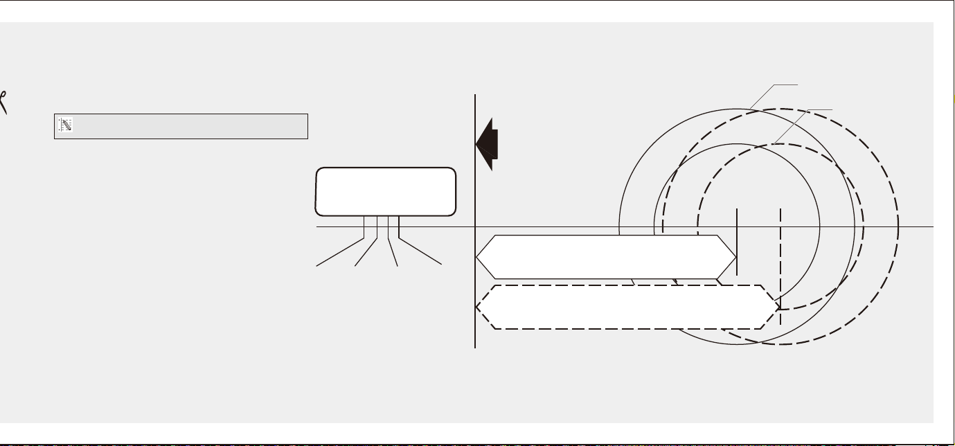
TEMPLATE
NOTE: Double check your product for the correct hole sizes.
The latch bolt should be
in retracted position.
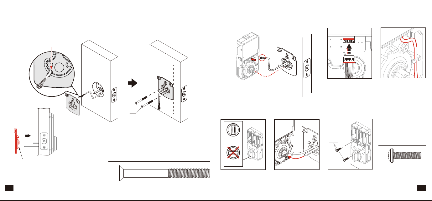
AA
Slide the cable through the
notch in mounting plate.
BB
Hardware Used (Actual Size)
Note : The metal connector
side should face outward.
Connect the cable rmly
into connector port.
The cable must be arranged
as shown in the diagram.
Insert the torque blade into the
interior slot of the thumbturn.
BB
Insert screws and tighten.
CORRECT
WRONG
Keep the thumbturn in
vertical position.
CC
Hardware Used (Actual Size)
CC
Hardware Used (Actual Size)
CC
I
H
CC
Tap latch ush
AA
AA
AA
AA
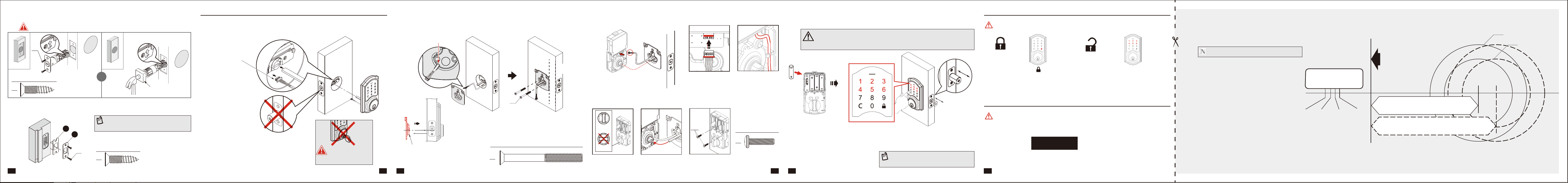
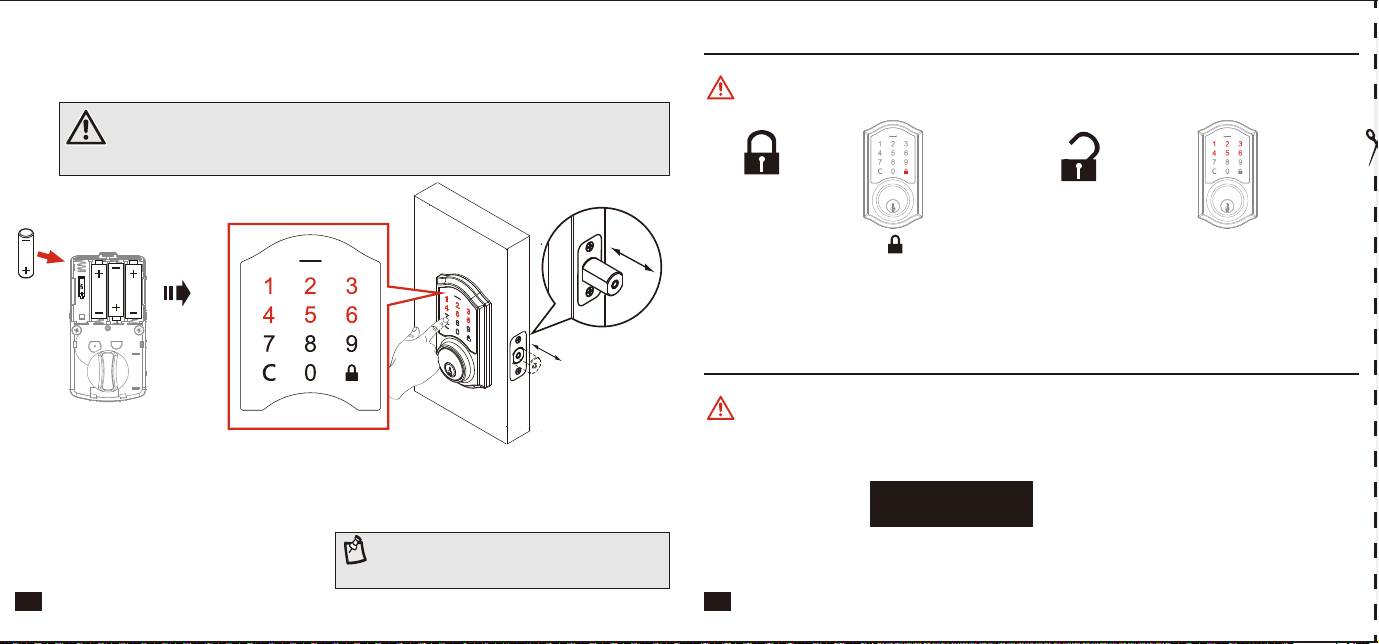
Install batteries
CAUTION :
Please use four alkaline batteries for better performance. Be sure to insert them correctly by
matching the + and – polarity markings. Do not mix old batteries and new batteries or standard
(carbon-zinc) with alkaline batteries.
Test lock with door OPENED to avoid being locked out.
Enter default Master Code(
123456
).
The detection of the bolt direction takes
10 seconds to complete. Wait until the
Green LED lights up.
See the
User Guide
for additional information.
NOTE:
If Red LED lights up with 3 beeps, refer to
Troubleshooting section or contact
customer service for further assistance.
Step 3: Install Electronic Deadbolt Step 4: Test Lock
Step 5: Program Lock
Promptly change the Master Code before operating this lockset.
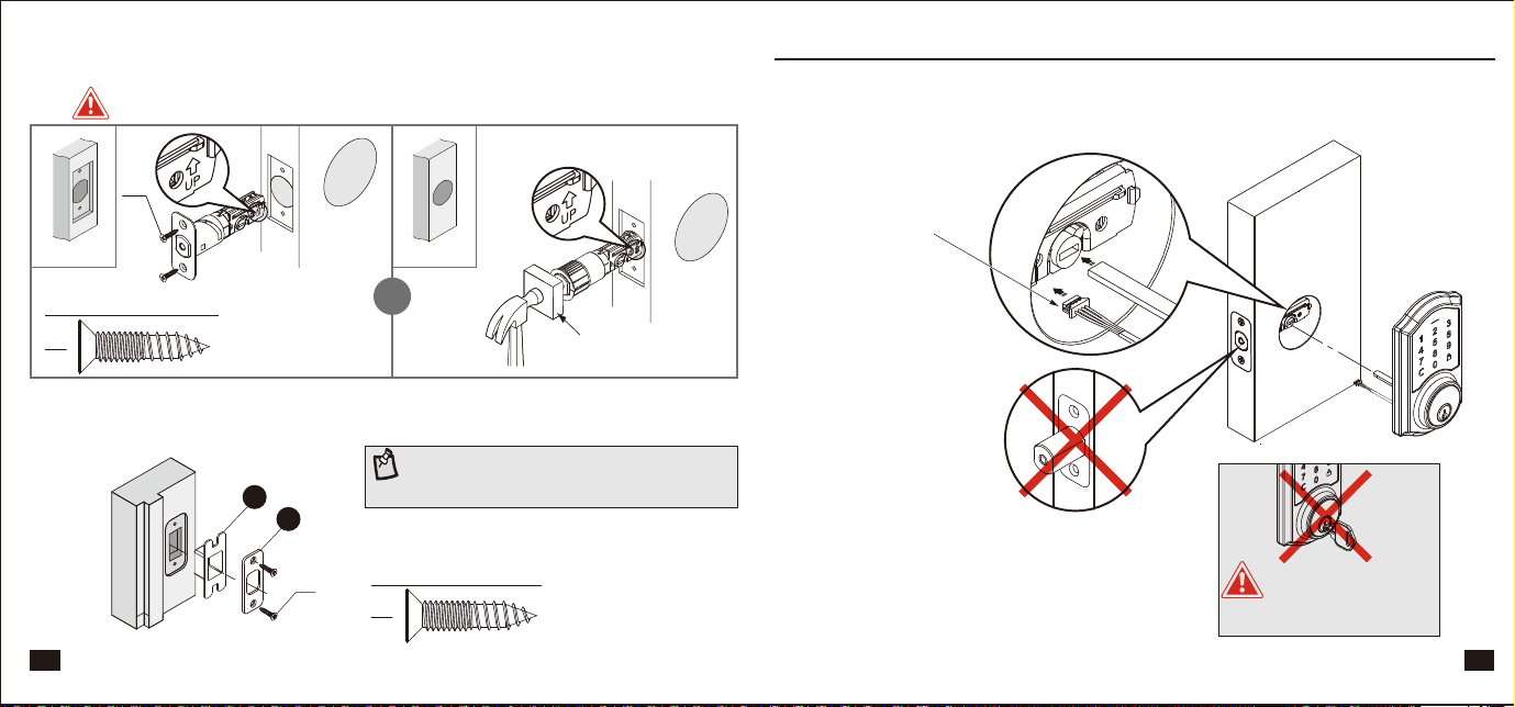
Install the latch
Install strike plate in door jamb
Insert screws and tighten.
Edge of door
08
09 10 11
06
07
OR
You must use the latch that was provided in the packaging.
Edge of door
Rotate torque blade to t in latch.
Cable goes underneath latch.
Fasten the mounting plate to door
Connect the cable rmly into connector port Install batteries and perform automatic bolt direction determination
Install interior assembly
Installing the lock assemblies
AA
Hardware Used (Actual Size)
Keep parallel
to door edge.
Wood block (not included)
To unlock
To lock
Enter default Master Code
123456
to unlock.
Press “ ” to lock.
NOTE:
Check the strike plate to make sure it is
properly aligned and clear so the bolt can freely
move in the hole.
1-3/4”
(45 mm)
1-3/8”
(35 mm)
1-9/16”
(40 mm)
2”
(51 mm)
Ø 2-1/8” (54 mm)
Ø 1-1/2” (38 mm)
Drill a 1” (25 mm) diameter
hole at the center of the door
edge.
Fold here.
Place on the door edge.
2-3/4” (70 mm)
2-3/8” (60 mm)
Backset
Backset
Drive-in latch
Do NOT leave the key in
the cylinder during
installation.
The bulged part of the mounting
plate must face towards the door.
Tighten the screws evenly.
Insert key and test latch. If latch does not extend or
retract smoothly, adjust Mounting Bolts (AA). Remove key
when nished and make sure the latch bolt is retracted.
TEMPLATE
NOTE: Double check your product for the correct hole sizes.
The latch bolt should be
in retracted position.
AA
Slide the cable through the
notch in mounting plate.
BB
Hardware Used (Actual Size)
Note : The metal connector
side should face outward.
Connect the cable rmly
into connector port.
The cable must be arranged
as shown in the diagram.
Insert the torque blade into the
interior slot of the thumbturn.
BB
Insert screws and tighten.
CORRECT
WRONG
Keep the thumbturn in
vertical position.
CC
Hardware Used (Actual Size)
CC
Hardware Used (Actual Size)
CC
I
H
CC
Tap latch ush
AA
AA
AA
AA
Install batteries
CAUTION :
Please use four alkaline batteries for better performance. Be sure to insert them correctly by
matching the + and – polarity markings. Do not mix old batteries and new batteries or standard
(carbon-zinc) with alkaline batteries.
Test lock with door OPENED to avoid being locked out.
Enter default Master Code(
123456
).
The detection of the bolt direction takes
10 seconds to complete. Wait until the
Green LED lights up.
See the
User Guide
for additional information.
NOTE:
If Red LED lights up with 3 beeps, refer to
Troubleshooting section or contact
customer service for further assistance.
Step 3: Install Electronic Deadbolt Step 4: Test Lock
Step 5: Program Lock
Promptly change the Master Code before operating this lockset.
Install the latch
Install strike plate in door jamb
Insert screws and tighten.
Edge of door
08
09 10 11
06
07
OR
You must use the latch that was provided in the packaging.
Edge of door
Rotate torque blade to t in latch.
Cable goes underneath latch.
Fasten the mounting plate to door
Connect the cable rmly into connector port Install batteries and perform automatic bolt direction determination
Install interior assembly
Installing the lock assemblies
AA
Hardware Used (Actual Size)
Keep parallel
to door edge.
Wood block (not included)
To unlock
To lock
Enter default Master Code
123456
to unlock.
Press “ ” to lock.
NOTE:
Check the strike plate to make sure it is
properly aligned and clear so the bolt can freely
move in the hole.
1-3/4”
(45 mm)
1-3/8”
(35 mm)
1-9/16”
(40 mm)
2”
(51 mm)
Ø 2-1/8” (54 mm)
Ø 1-1/2” (38 mm)
Drill a 1” (25 mm) diameter
hole at the center of the door
edge.
Fold here.
Place on the door edge.
2-3/4” (70 mm)
2-3/8” (60 mm)
Backset
Backset
Drive-in latch
Do NOT leave the key in
the cylinder during
installation.
The bulged part of the mounting
plate must face towards the door.
Tighten the screws evenly.
Insert key and test latch. If latch does not extend or
retract smoothly, adjust Mounting Bolts (AA). Remove key
when nished and make sure the latch bolt is retracted.