HARDWARE CONTENTS (Actual Size)
TEMPLATE
NOTE: Double check
your product for the
correct hole sizes.
1-3/4”
(45 mm)
1-3/8”
(35 mm)
1-9/16”
(40 mm)
2”
(51 mm)
Ø 2-1/8” (54 mm)
2-3/4” (70 mm)
2-3/8” (60 mm)
Drill a 1” (25 mm) diameter
hole at the center of the door
edge.
Fold here.
Place on the door edge.
Backset
Backset
1-3/4”
(45 mm)
1-3/8”
(35 mm)
1-9/16”
(40 mm)
2”
(51 mm)
Ø 1-1/2” (38 mm)
2-3/4” (70 mm)
2-3/8” (60 mm)
Drill a 1” (25 mm) diameter
hole at the center of the door
edge.
Fold here.
Place on the door edge.
Backset
Backset
OR
WARRANTY
CAUTION:
Please use four alkaline batteries for the best performance.
CARE and MAINTENANCE:
The following instructions should be followed to properly protect and maintain your lockset:
Read the precautions and instructions in this manual before installing and using this lock. Save this manual for future reference.
A. Remove locks, or do not install locks, prior to painting your door.
B. Periodically clean with mild soap and a soft cloth only.
C. Do not use any abrasives or chemical products containing alcohol, benzene, acids, and avoid using sharp or abrasive objects to clean this lockset.
D. Do not allow any water or liquids into the lockset during installation.
A. Do not attempt to disassemble any internal components of the lockset. Doing so will void the limited warranty.
B. Do not drop or hit the lockset. Too much shock may result in permanent damage.
C. Do not use pins or sharp objects to press the keypad.
D. Always create a backup of information you wish to keep (Master Code, User Codes,etc.) Please use the last page of this booklet as a reference.
E. Promptly change the Master Code before operating this lockset
WARNING:
If the door needs to be drilled, please be familiar with how to use a drill safely and understand all of the door preparation steps before proceeding.
2
SAFETY INFORMATION
1
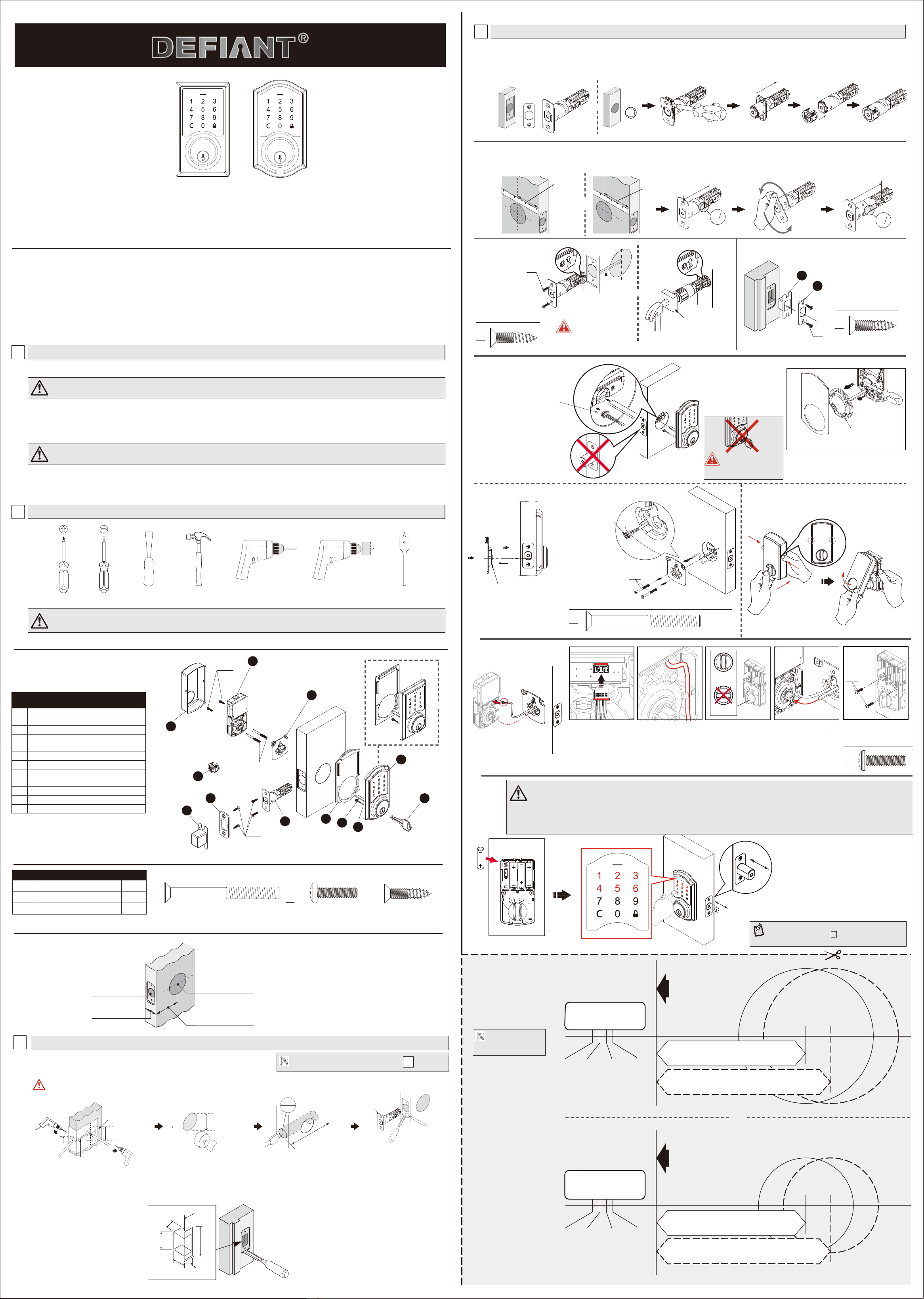
PRE-INSTALLATION – TOOLS REQUIRED / HARDWARE INCLUDED
LIMITED LIFETIME MECHANICAL AND 1 YEAR ELECTRONIC WARRANTY
The retailer of this product, hereby warrants, subject to the conditions set forth below, that it will either repair or replace, at its option, this product if it
proves to be defective by reason of improper workmanship or materials within the original purchaser's limited time. In order to obtain repairs or
replacement under this limited warranty you must bring this product to the retailer's store in which you bought it.
Original purchaser: This limited warranty is limited to the original purchaser at retail of this product from retailer.
Except to the extent prohibited by applicable law, no other warranties, whether express or implied, including the warranties of merchantability and tness
for a particular purpose, shall apply to this product. Under no circumstances shall retailer be liable for consequential or incidental damages in connection
with this product. To the extent retailer is prohibited by applicable law from excluding implied warranties, the duration of such implied warranties which
are not excludable shall be the original purchaser's lifetime. Some states do not allow the limitation on how long an implied warranty lasts, so the above
limitation on the duration of implied warranties which are not excludable, if any, may not apply to you. Some states do not allow the exclusion or limitation
of incidental or consequential damages, so the above limitation or exclusion of incidental or consequential damages may not apply to you.
Retailer neither assumes not authorizes any representative or other person to assume for it any obligation or liability other than such as is expressly set
forth herein. This limited warranty gives you specic legal rights, and you may also have other rights which vary from state to state.
FOR
G32-KPDAH12-XQ Rev. 20/02-01
Optional Optional Optional Optional Optional Optional
1-13/16" (46 mm) Mounting Bolt
BB 3/4" (19 mm) Screw
CC 3/4" (19 mm) Wood Screw
Part
Description
2
2
4
Quantity
AA
BB
AA
CC
PACKAGE CONTENTS LIST
CUT OUT TEMPLATE AND USE TO MARK THE DOOR, DRILL HOLES, AND CHISEL OUT THE MORTISE.
WARNING: Drill from both sides of the door to prevent wood splitting.
3
DOOR DRILLING FOR NEW INSTALLATION
1"
(25 mm)
2-1/8"(54 mm)
1-1/2"(38 mm)
or
Backset
Centerline
2-1/8"(54 mm)
1-1/2"(38 mm)
or
1”
(25 mm)
Outline
Chisel 5/32” (4 mm) deep
Faceplate
c
b
f
e
a
d
PREPARE THE DOOR JAMB – USE THE STRIKE PLATE AS A TEMPLATE TO DRILL THE LATCH AND SCREW HOLES AND CHISEL OUT THE MORTISE. THE STRIKE PLATE MUST
FIT FLUSH WITH THE SURFACE OF THE DOOR JAMB.
Door jamb hole dimension
Strike dimentions
b. 1-9/64"(29 mm)
d. 5/32"(4 mm)
e. 2-1/4"(57 mm)
f. 1"(25 mm)
a. 1-3/16"(30 mm)
c. 7/8"(22 mm)
For 2-3/8” (60 mm) backset: 3-7/16” (87 mm)
For 2-3/4” (70 mm) backset: 3-13/16” (97 mm)
Depth of latch hole
Flat head screwdriver
4
INSTALLATION
A. Attach the correct faceplate
INSTALLING THE LATCH
Edge of door
OR
Faceplate
Edge of door
Drive-in
collar
BEFORE PROCEEDING
Check Dimensions
1-3/8” - 2”
(35mm - 51mm)
2-3/8” (60mm)
OR
2-3/4” (70mm)
1-1/2” (38mm)
OR
2-1/8” (54mm)
1” (25mm)
NOTE:
If your door already has holes, skip to step
4
OR
I Dust Box
J Key
K Drive-in Collar (Optional)
L Exterior Gasket
E Interior Assembly 1
F Battery Cover 1
G Latch 1
H Strike Plate 1
2
1
1
1
A Exterior Assembly
B Power Cable
C Torque blade
D Mounting Plate
1
1
Part
Description
Quantity
1
1
F
BB
E
I
H
K
J
A
B
C
L
D
G
B
CC
AA
Slide the cable
through the notch in
mounting plate.
B. Set the latch backset length
The bulged part of the mounting plate
must face towards the door.
B. Install the lock assemblies
INSTALLING THE LOCK ASSEMBLIES
C. Install the latch
OR
Drive-in latch
AA
Hardware Used (Actual Size)
CC
Hardware Used (Actual Size)
Your latch is set for 2-3/8” backset. It can be adjusted if needed to 2-3/4” (skip this if your door has a 2-3/8” backset).
Backset
CC
Press
Remove the Battery Cover
The latch bolt should be
in retracted position.
You must use the latch
that was provided in the
packaging.
For installation into 1-1/2”(38mm) bore hole,
simply pry the adapter collar off with a
screwdriver.
A. Thread the cable through
the hole and under the latch.
Adapter collar
CC
D. Install strike plate in door jamb
I
H
Wood block (not included)
Tap latch ush
BB
Hardware Used (Actual Size)
Note : The metal
connector side should
face outward.
CORRECT
WRONG
BB
Connect the cable rmly
into connector port .
The cable must be
arranged as shown in
the diagram.
Keep the thumbturn in
vertical position.
Insert the torque blade
into the interior slot of the
thumbturn.
Insert screws and tighten.
AA
AA
AA
AA
Install batteries
CAUTION :
1.Please use four alkaline batteries for better performance. Be sure to insert them correctly by matching the + and –
polarity markings. Do not mix old batteries and new batteries or standard (carbon-zinc) with alkaline batteries.
2.Please activate the lockset by entering the DEFAULT MASTER CODE (
123456) to nish installation.
3.Install and test lock with door OPENED to avoid being locked out.
Enter default Master Code(123456).
The detection of the bolt direction takes 10 seconds to
complete. Wait until the Green LED lights up.
NOTE: If Red LED lights up with 3 beeps, refer to
Troubleshooting section or contact customer
service for further assistance.
-
3
Questions, problems, missing parts? Before returning to the store,
call Deant Customer Service
TOLL FREE HELP LINE 1-877-ONE-LOCK
HOMEDEPOT.COM
08:30 a.m.-05:30 p.m., EST, Monday - Friday
AA
CC
Hardware Used (Actual Size)
OR
2-3/8’’
(60 mm)
2-3/4’’
(70 mm)
2
8
3
2
8
3
2
-
3
/
8
”
(
6
0
m
m
)
180º
2
8
3
2
8
3
2
4
3
2
4
3
2
-
3
/
4
”
(
70
m
m
)
Note: For drive-in latch.
Simply insert latch.
Do NOT leave the key in
the cylinder during
installation
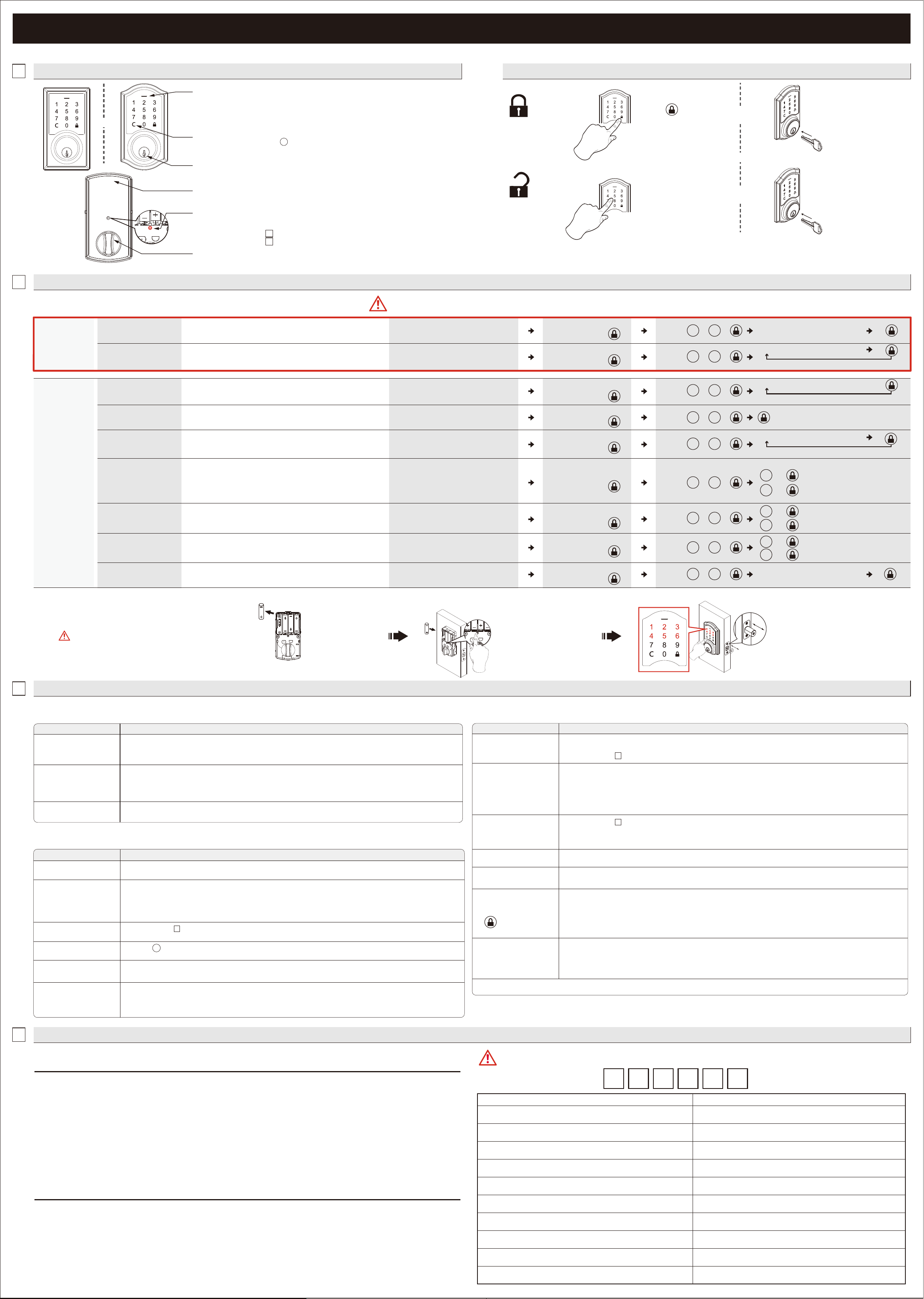
PROGRAMMING
1
OVERVIEW OF FUNCTIONS
2
PROGRAMMING
HOW TO LOCK / UNLOCK THE LOCKSET
To unlock
To lock
Use a mechanical key to lock.
4
ACCESS CODE LIST
OR
OR
3
TROUBLESHOOTING
CLEAR BUTTON
1. Please always press button to cancel any typo or exit
programming mode.
1. Protect the batteries from unexpected damage.
BATTERY COVER
1. Lock or unlock the lockset by a valid key.
MECHANICAL KEYWAY OVERRIDE
INDICATORS
1. Red light: Represents an incorrect entry or the unit is
programming mode.
2. Yellow light: Flashes when the batteries are low in power.
3. Green light: Represents a correct entry.
Enter a valid User Code
or the current Master
Code to unlock.
Press “ ” to lock.
Use a mechanical key to unlock.
INSTALLATION
ANSWERSQUESTIONS
A.The latch does not operate
correctly after installation.
1. Make sure the backset on the latch is set to the proper length.
2. Make sure prior to installation latch bolt is retracted and key is not in lockset when installing the deadbolt.
3. Please restore to factory setting and enter the default Master Code to set up the lock.
B. Feel a bump while turning
the thumbturn or the key?
1. Please execute lock & unlock function to allow the motor to reposition itself again.
2. The battery is low if the battery indicator light keeps ashing. Please replace with four new batteries. Hold the set
button until long beep over.
3. Please restore to factory setting and enter the default
Master Code to set up the lock.
OPERATION
ANSWERSQUESTIONS
A. Battery indicator keeps
ashing.
1. The batteries are getting low, please replace with four new batteries for the best performance (alkaline batteries only ).
B. Keypad not responding. 1. Make sure the batteries are installed properly.
2. The batteries are getting low if the battery indicator keeps ashing. please replace with four new batteries for the
best performance (alkaline batteries only ).
3. Make sure the cable is well-connected to the port, and was not damaged during installation.
4. Please make sure the lock has been set up and complete the bolt direction determination.
D. What should I do if wrong
code was entered?
1. Press button once and continue to input code according to regular procedures.
C. Master Code can not be
changed.
1. Please refer to in the user guide to restore factory setting and reprogram all codes.
-
2
E. Can not delete all User
Codes.
1. Make sure the whole code entering process is completed within 10 seconds, otherwise the unit will time out.
2. Make sure the
Master Code has been entered correctly.
C. Fail to set up the lock. 1. Please make sure the lock is installed correctly.
2. Please install the fresh batteries and make sure the cable is connected correctly.
ANSWERSQUESTIONS
M. I cannot remove my key
unless it is in the locked
position.
If the lock appears to be damaged or does not operate properly, please contact customer service for further assistance.
1. Un-install the interior and exterior assemblies.
Before re-installation, please follow these guidelines:
1) Make sure the bolt is in the retracted position.
2) Do not have any key in lock cylinder.
3) Make sure the torque blade is inserted horizontally.
K. The red indicator is still on
after setting is completed.
1. Check if [SET] button is jammed.
2. Re-install the batteries.
L. The lockset locks when I
enter my code and
unlocks when I press the
.
1. Un-install the interior and exterior assemblies.
Before re-installation, please follow these guidelines:
1) Make sure the bolt is in the retracted position.
2) Do not have any key in the cylinder durring installation.
3) Make sure the torque blade is inserted horizontally.
4) Reset the unit to factory settings and reprogram the
Master Code and user codes.
J. How to operate the lockset
in darkness?
1. Press any button to activate the lockset back light.
F. Can not add a new
User Code.
1. Make sure the whole code entering process is completed within 10 seconds, otherwise the unit will time out.
2. Make sure the
Master Code has been entered correctly.
3. The new User Code will not be accepted when the capacity is full. Try to delete any or some existing User Codes and
then add new one(s) again. A User Code must be at least 4 to 6 digits.
H. Lockset is not able
to unlock / lock by
keypad.
1. Make sure you have entered the correct User Code.
2. The battery is low if the battery indicator light keeps ashing. Please replace with four new batteries.
3. Make sure the cable is rmly connected.
4. Check the cable for any damage that may have occurred during installation.
5. Make sure the batteries are properly installed. (Alkaline batteries only)
6. Check the strike plate to make sure it is properly aligned and clear so the bolt can freely move in the hole.
G. "Auto lock" does not
function.
1. The batteries are low on power if the battery indicator keeps ashing. Please replace with four new batteries for the
best performance. (Alkaline Batteries Only).
2. Please refer to in the guide to enable the Auto-Lock function.
-
2
I. Lockset is unable to
reset.
1. Please refer to in the user guide to restore factory settings and reprogram all codes. Hold the set button until
long beep over.
2. The battery is low if the battery indicator light keeps ashing. Please replace with four new batteries. Hold the set
button until long beep over.
-
2
FEDERAL COMMUNICATIONS COMMISSION STATEMENT
RESTORE TO FACTORY SETTINGS
Enter the default Master Code (123456) to
complete the bolt direction setting.
Change the Master Code before operating the lock.
Remove one battery
AA
AA
AA
AA
AA
AA
AA
AA
AA
MASTER CODE (6 digits)
After changing your Master Code, do not pass your Master Code to anyone else.
WRITE YOUR MASTER CODE HERE FOR EASY ACCESS
Name User Code (4-6 digits)
This will erase all stored information, including the current
Master Code and existing User Codes.
OR
Press and hold SET button while
inserting the battery back. Hold
the set button until a long beep is
heard followed by a short beep.
[SET] BUTTON
1. Press set button untill the unit beeps to enter programming mode
2. Please refer to for more information about programming mode.
3. Please refer to for steps to restore to factory settings.
2
-
2
-
INTERIOR THUMBTURN
1. Lock or unlock the lockset manually.
C
HOW TO PROGRAM THE LOCKSET BY FUNCTION CODES (Programming Mode)
・A Master Code can be used to program or unlock the lock.
・The preset Master Code is 123456.
・Please change the Master Code before operating the lock.
Change the existing
Master Code
Enter New Master Code (6 digits)
Add user code(s)
・The unit can store up to 10 customized User Codes (4-6 digits long).
Enter New User Code (4-6 digits)
Add another code
BASIC
SETTINGS
Press and hold the [SET] button until the
unit beeps, then release the [SET] button
Press and hold the [SET] button until the
unit beeps, then release the [SET] button
Press
Enter current Master Code
(6 digits) then press
・The single-entry user code can be used for only one successful entry
and will be invalid when the lockset is locked again.
・The unit can store up to 5 single-entry user codes (4 digits long).
Add single-entry code(s)
Enter New Single-entry Code (4 digits)
Vacation mode
Volume Control
・The beeper can be turned off if desired. Beeps will still sound during
programming.
Auto-lock function
・Disabled by default.
・When enabled, the lock will automatically re-lock after unlocking
(Default: 10 seconds).
Auto-lock delay timer
Enter new digits (10 - 99 seconds)
・Auto-lock timer can be set from 10 to 99 seconds according to your
demand.
Add another code
ADVANCED
SETTINGS
Press and hold the [SET] button until the
unit beeps, then release the [SET] button
Press and hold the [SET] button until the
unit beeps, then release the [SET] button
Press and hold the [SET] button until the
unit beeps, then release the [SET] button
Press and hold the [SET] button until the
unit beeps, then release the [SET] button
Press and hold the [SET] button until the
unit beeps, then release the [SET] button
Turn On.
+
Turn Off.
+
・Disabled by default.
・When Vacation Mode is enabled, only the current Master Code
(6 digits)
can unlock the lock.
・The stored User / Single-entry Codes will be re-activated once the
Vacation Mode is disabled.
・Programming Mode will automatically time out after 10 seconds of inactivity.
・If you make a mistake during programming, press the interior SET BUTTON (as shown in above diagram) to leave Programming Mode and start over.
1
0
Enter current Master Code
(6 digits) then press
Enter current Master Code
(6 digits) then press
Enter current Master Code
(6 digits) then press
Enter current Master Code
(6 digits) then press
Enter current Master Code
(6 digits) then press
Enter current Master Code
(6 digits) then press
Press
2
0
Press
2
1
1
Press
5
0
Turn On.
+
1
0
Turn Off.
+
0
Turn On.
+
1
Turn Off.
+
0
Press
6
0
Press
8
0
Press
7
0
C
This device complies with Part 15 of the FCC Rules. Operation is subject to the following two conditions:
(1) this device may not cause harmful interference, and (2) this device must accept any interference received, including interference that may
cause undesired operation.
Changes or modications not expressly approved by the party responsible for compliance could void the user's authority to operate the equipment.
NOTE: This equipment has been tested and found to comply with the limits for a Class B digital device, pursuant to part 15 of the FCC Rules.
These limits are designed to provide reasonable protection against harmful interference in a residential installation. This equipment generates,
uses and can radiate radio frequency energy and, if not installed and used in accordance with the instructions, may cause harmful interference
to radio communications. However, there is no guarantee that interference will not occur in a particular installation. If this equipment does cause
harmful interference to radio or television reception, which can be determined by turning the equipment off and on, the user is encouraged to
tryto correct the interference by one or more of the following measures:
- Reorient or relocate the receiving antenna.
- Increase the separation between the equipment and receiver.
- Connect the equipment into an outlet on a circuit different from that to which the receiver is connected.
- Consult the dealer or an experienced radio/TV technician for help.
This Class B digital apparatus complies with Canadian ICES-003.
Operation is subject to the following two conditions:
(1) this device may not cause harmful interference, and (2) this device must accept any interference received, including interference that may
cause undesired operation of the device.
IC REGULATIONS
Enter unwanted User Code (4-6 digits)
Delete individual user or
single-entry code(s)
Delete all user /
single-entry codes
・Delete one or more codes at a time, including User Codes or Single-
entry Codes.
・Users/Single-entry codes cannot be retrieved after they are deleted.
・Delete ALL User Codes at once.
・Use the existing Master Code (6 digits) to unlock the unit after the
deletion of User/Single-entry Codes.
Delete another code
Press and hold the [SET] button until the
unit beeps, then release the [SET] button
Press and hold the [SET] button until the
unit beeps, then release the [SET] button
Enter current Master Code
(6 digits) then press
Enter current Master Code
(6 digits) then press
Press
3
0
Press
4
0