VTSW4 USER MANUAL
4 CHANNEL VIDEO SWITCH BOX
OPERATION
The VTSW4 allows four cameras to be connected and displayed onto a single channel
monitor. Each camera is displayed individually onto the monitor when the corresponding
trigger wire is activated. For example, left side mount camera is displayed on the monitor
when left turn signal is activated, right side mount camera displayed on the monitor when
the right turn signal is activated. Rear camera is displayed on the monitor when in reverse
gear. The front camera is always displayed on the monitor when there are no triggers
activated.
Note: The front camera can be converted to be manually triggered with an optional ON/OFF
switch.

CONNECTIONS
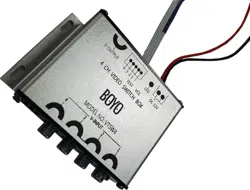
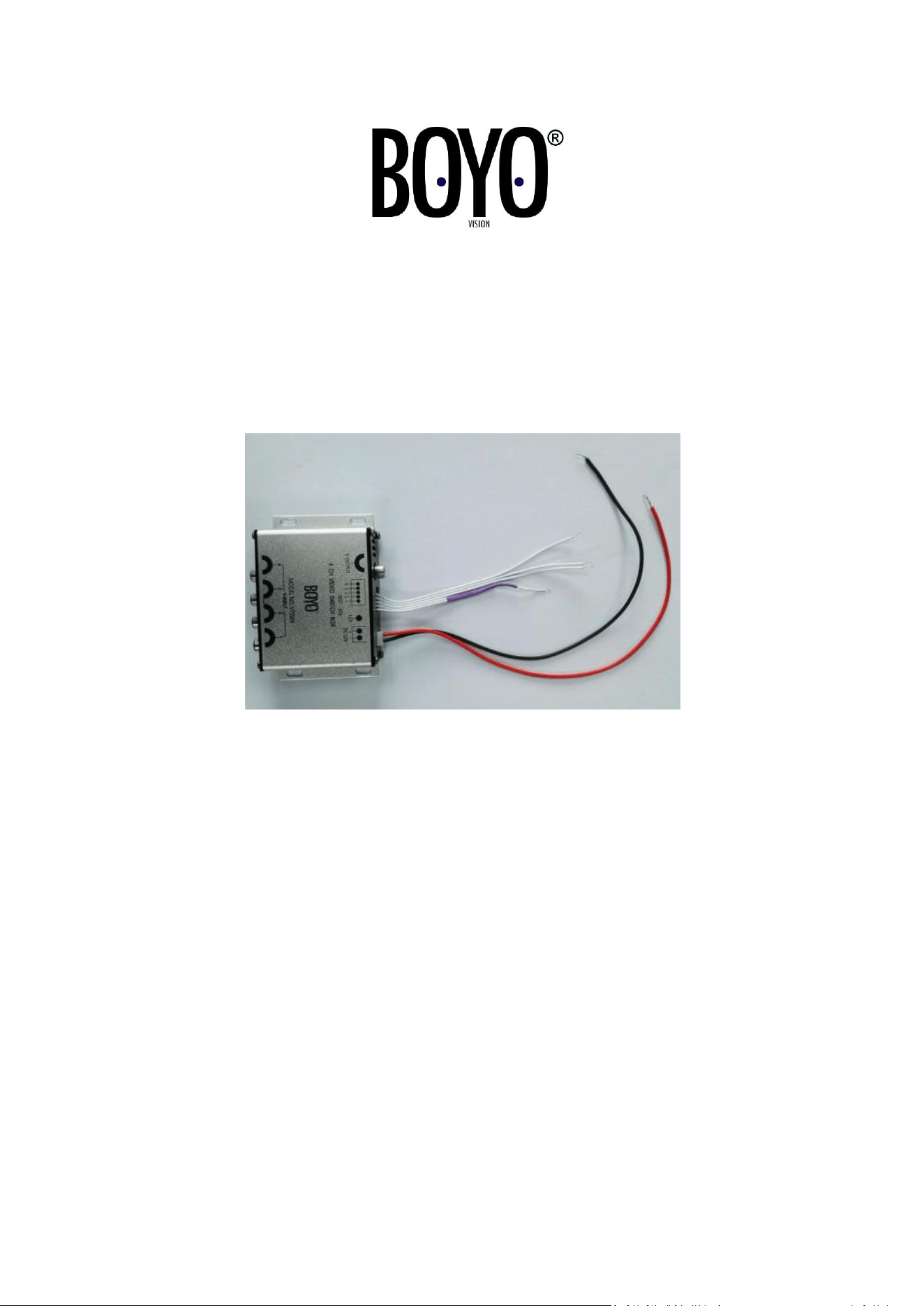
1. Connect the RED wire to the vehicle accessory wire. (Switched +12 volts)
2. Connect the BLACK wire to chassis ground.
3. Channel 1 Trigger wire, FRONT camera trigger is Default on.
NOTE: An optional trigger switch can be installed to control when the front camera is
displayed. Separate the two connected white wires and install an ON/OFF switch.
4. Channel 2 Trigger wire, LEFT camera trigger.
Connect this wire to the +12 volt left turn signal wire.
5. Channel 3 Trigger wire, RIGHT camera trigger.
Connect this wire to the +12 volt right turn signal wire.
6. Channel 4 Trigger wire, REAR camera trigger.
Connect this wire to the +12 volt reverse light signal wire.
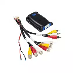
7. Connect the RCA cable from each camera to the corresponding 1-4 video inputs.
CHANNEL 1 = FRONT CAMERA
CHANNEL 2 = LEFT CAMERA
CHANNEL 3 = RIGHT CAMERA
CHANNEL 4 = REAR CAMERA
SPECIFICATIONS
4 Channel RCA Video Inputs
1 Channel RCA Video Output to Monitor
4 Trigger Wires for each Video Input
Working Voltage: 12 VOLTS DC
System: PAL / NTSC / SECAM
Video Output: 1.0VPP/75 ohm
Working Temperature: -4° F - 158° F
Vision Tech America, Inc.
1452 E. Valencia Dr.
Fullerton, CA 92831
Tel: 714-446-0543

For technical support, Call 888-941-3060 or Email info@visiontechamerica.com
WWW.VISIONTECHAMERICA.COM