Loading ...
Loading ...
Loading ...
7
5. Drainage piping work
Outdoor unit drainage pipe connection
When drain piping is necessary, use the drain socket or the drain pan (option).
A12, A18 A24, A30 A36, A42
Drain socket PAC-SJ08DS-E PAC-SG61DS-E
Drain pan PAC-SG63DP-E PAC-SG64DP-E PAC-SH97DP-E
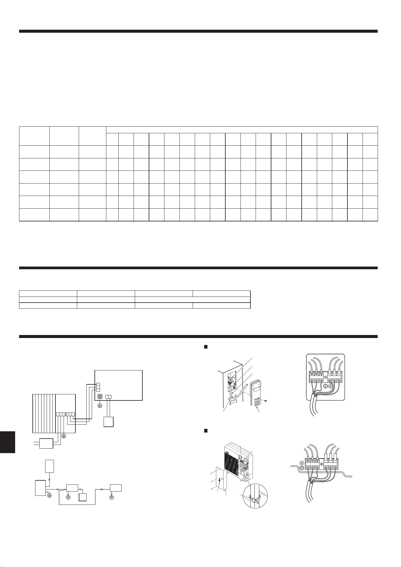
6. Electrical work
6.1. Outdoor unit (Fig. 6-1, Fig. 6-2)
1 Remove the service panel.
2 Wire the cables referring to the Fig. 6-1 and the Fig. 6-2.
Fig. 6-1
Fig. 6-2
A12, A18
A
C
C
E
E
E
E E
S3
S3
S2
S1
S2S1L1 L2
GR
A
B
B
D
D
A
A24-A42
E
B
A
F
C
L1
GR
L2 S1 S2 S3
A
B
C
D
E
L1
GR
L2 S1 S2 S3
A Indoor unit
B Outdoor unit
C Remote controller
D Main switch (Breaker)
E Earth
A Earth terminal
B Terminal block
C Clamp
D Service panel
For Power
For Power
4.6. Addition of refrigerant
• Additional charging is not necessary if the pipe length does not exceed 21 m, 70 ft
for A12-A30, 30 m 100 ft for A36, A42.
• Especially, additional charging is not necessary if the pipe length does not exceed
30 m 100 ft for A24, 30, 36, A42 connected to the A-COIL indoor unit (PAA-A18,
24, 30, 36, 42).
•
If the pipe length exceeds the specied length above, charge the unit with additional
R410A refrigerant according to the permitted pipe lengths in the chart below.
Notes:
1. When the unit is stopped, charge the unit with the additional refrigerant through
the liquid stop valve after the pipe extensions and indoor unit have been vacu-
umized.
When the unit is operating, add refrigerant to the gas check valve using a
safety charger. Do not add liquid refrigerant directly to the check valve.
2. After charging the unit with refrigerant, note the added refrigerant amount on
the service label (attached to the unit).
Refer to the “1.5. Using R410A refrigerant air conditioners” for more informa-
tion.
• Be careful when installing multiple units. Connecting to an incorrect indoor unit
can lead to abnormally high pressure and have a serious effect on operation per-
formance.
Model
Max pipe
length
Max height
difference
Additional refrigerant charging amount (kg/oz) *2
21 m
70 ft
24 m
80 ft
27 m
90 ft
30 m
100 ft
34 m
110 ft
37 m
120 ft
40 m
130 ft
43 m
140 ft
46 m
150 ft
49 m
160 ft
50 m
165 ft
52 m
170 ft
55 m
180 ft
58 m
190 ft
61 m
200 ft
64 m
210 ft
67 m
220 ft
69 m
225 ft
PUZ-A12, 18
30 m, 100 ft
30 m, 100 ft 0
0.06 kg
2 oz
0.11 kg
4 oz
0.17 kg
6 oz
--------------
PUZ-A24, 30
50 m, 165 ft *1
30 m, 100 ft 0
0.20 kg
7 oz
0.40 kg
14 oz
0.60 kg
21 oz
0.79 kg
28 oz
0.99 kg
35 oz
1.19 kg
42 oz
1.39 kg
49 oz
1.59 kg
56 oz
1.79 kg
63 oz
1.89 kg
67 oz
-------
PUZ-A36, 42
50 m, 165 ft *1
30 m, 100 ft 0 0 0 0
0.20 kg
7 oz
0.40 kg
14 oz
0.26 kg
21 oz
0.79 kg
28 oz
0.99 kg
35 oz
1.19 kg
42 oz
1.29 kg
46 oz
-------
PUY-A12, 18
50 m, 165 ft
30 m, 100 ft 0
0.03 kg
1 oz
0.06 kg
2 oz
0.09 kg
3 oz
0.11 kg
4 oz
0.14 kg
5 oz
0.17 kg
6 oz
0.20 kg
7 oz
0.23 kg
8 oz
0.26 kg
9 oz
0.27 kg
10 oz
-------
PUY-A24, 30
69 m, 225 ft *1
30 m, 100 ft 0
0.09 kg
3 oz
0.17 kg
6 oz
0.26 kg
9 oz
0.34 kg
12 oz
0.43 kg
15 oz
0.51 kg
18 oz
0.60 kg
21 oz
0.68 kg
24 oz
0.77 kg
27 oz
0.81 kg
29 oz
0.85 kg
30 oz
0.94 kg
33 oz
1.02 kg
36 oz
1.11 kg
39 oz
1.19 kg
42 oz
1.28 kg
45 oz
1.32 kg
47 oz
PUY-A36, 42
69 m, 225 ft *1
30 m, 100 ft 0 0 0 0
0.09 kg
3 oz
0.17 kg
6 oz
0.26 kg
9 oz
0.34 kg
12 oz
0.43 kg
15 oz
0.51 kg
18 oz
0.55 kg
20 oz
0.60 kg
21 oz
0.68 kg
24 oz
0.77 kg
27 oz
0.85 kg
30 oz
0.94 kg
33 oz
1.02 kg
36 oz
1.06 kg
38 oz
*1. If outdoor unit is connected to the A-COIL indoor unit (PAA-A18, 24, 30, 36, 42), pipe length is “Max. 30 m, 100 ft”.
*2. This additional refrigerant chart is used only when connected to an indoor unit other than A-COIL indoor unit (PAA-A18, 24, 30, 36, 42). Additional charging is not necessary
if the pipe length does not exceed 30 m 100 ft for A24, 30, 36, A42 connected to the A-COIL indoor unit (PAA-A18, 24, 30, 36, 42).
4. Installing the refrigerant piping
E Wire the cables so that they do not
contact the center of the service panel
or the gas valve.
en
BG79U896H14_01en.indd 7 2021/10/22 15:52:28
008
Loading ...
Loading ...
Loading ...