Loading ...
Loading ...
Loading ...
S1
S2
S3
S1
S2
S3
208/230V
9
6. Electrical work
Warning:
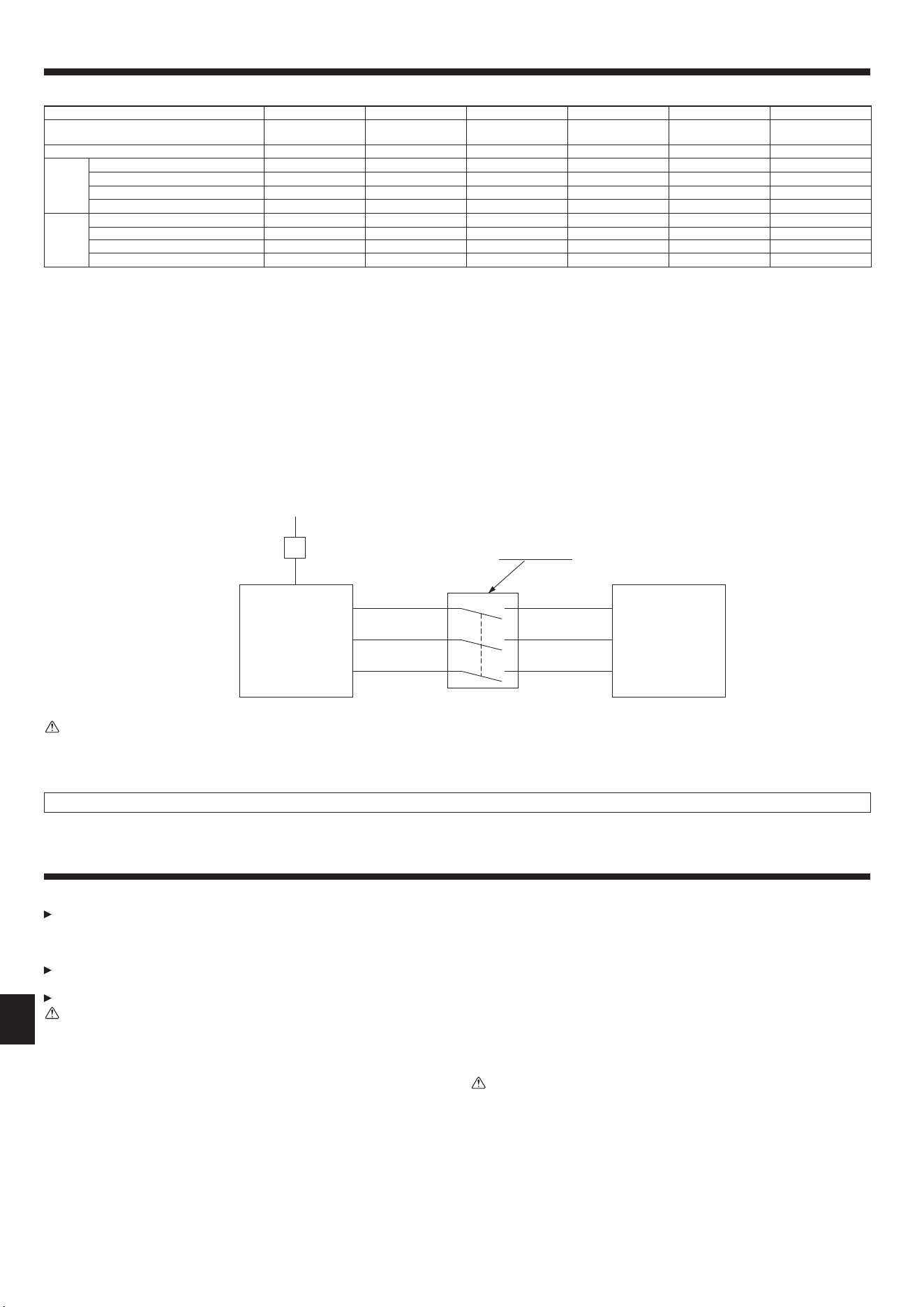
In case of A-control wiring, there is high voltage potential on the S3 terminal caused by electrical circuit design that has no electrical insulation between power
line and communication signal line. Therefore, please turn off the main power supply when servicing. And do not touch the S1, S2, S3 terminals when the power
is energized. If isolator should be used between indoor unit and outdoor unit, please use 3-pole type.
7. Test run
7.1. Before test run
After completing installation and the wiring and piping of the indoor and
outdoor units, check for refrigerant leakage, looseness in the power supply
or control wiring, wrong polarity, and no disconnection of one phase in the
supply.
Use a 500-volt megohmmeter to check that the resistance between the pow-
er supply terminals and ground is at least 1 MΩ.
Do not carry out this test on the control wiring (low voltage circuit) terminals.
Warning:
Do not use the air conditioner if the insulation resistance is less than 1 MΩ.
Insulation resistance
After installation or after the power source to the unit has been cut for an extended
period, the insulation resistance will drop below 1 MΩ due to refrigerant accumulat-
ing in the compressor. This is not a malfunction. Perform the following procedures.
1. Remove the wires from the compressor and measure the insulation resistance of
the compressor.
2. If the insulation resistance is below 1 MΩ, the compressor is faulty or the resist-
ance dropped due the accumulation of refrigerant in the compressor.
3. After connecting the wires to the compressor, the compressor will start to warm
up after power is supplied. After supplying power for the times indicated below,
measure the insulation resistance again.
• The insulation resistance drops due to accumulation of refrigerant in the com-
pressor. The resistance will rise above 1 MΩ after the compressor is warmed up
for 12 hours.
(The time necessary to warm up the compressor varies according to atmos-
pheric conditions and refrigerant accumulation.)
• To operate the compressor with refrigerant accumulated in the compressor, the
compressor must be warmed up at least 12 hours to prevent breakdown.
4. If the insulation resistance rises above 1 MΩ, the compressor is not faulty.
Caution:
• The compressor will not operate unless the power supply phase connection
is correct.
• Turn on the power at least 12 hours before starting operation.
- Starting operation immediately after turning on the main power switch can result
in severe damage to internal parts. Keep the power switch turned on during the
operational season.
6.2. Field electrical wiring
Outdoor unit model A12 A18 A24 A30 A36 A42
Outdoor unit power supply
~/N (single), 60Hz,
208/230 V
~/N (single), 60Hz,
208/230 V
~/N (single), 60Hz,
208/230 V
~/N (single), 60Hz,
208/230 V
~/N (single), 60Hz,
208/230 V
~/N (single), 60Hz,
208/230 V
Outdoor unit input capacity Main switch (Breaker) *1 15 A 15 A 25 A 25 A 30 A 30 A
Wiring Wire
No. x
size (mm
2
)
Outdoor unit power supply 2 x Min. AWG 14 2 × Min. AWG 14 2 × Min. AWG 12 2 × Min. AWG 12 2 × Min. AWG 10 2 × Min. AWG 10
Indoor unit-Outdoor unit *2 3 x AWG 14 (polar) 3 x AWG 14 (polar) 3 x AWG 14 (polar) 3 x AWG 14 (polar) 3 x AWG 14 (polar) 3 x AWG 14 (polar)
Indoor unit-Outdoor unit earth *2
1 x Min. AWG 14 (polar) 1 x Min. AWG 14 (polar)
1 x Min. AWG 14 (polar)
1 x Min. AWG 14 (polar) 1 x Min. AWG 14 (polar) 1 x Min. AWG 14 (polar)
Remote controller-Indoor unit *3
2 × AWG 22 (Non-polar) 2 x AWG 22 (Non-polar) 2 x AWG 22 (Non-polar) 2 x AWG 22 (Non-polar) 2 x AWG 22 (Non-polar) 2 x AWG 22 (Non-polar)
Circuit
rating
Outdoor unit L1-L2 (single) *4 208/230 V AC 208/230 V AC 208/230 V AC 208/230 V AC 208/230 V AC 208/230 V AC
Indoor unit-Outdoor unit S1-S2 (single) *4 208/230 V AC 208/230 V AC 208/230 V AC 208/230 V AC 208/230 V AC 208/230 V AC
Indoor unit-Outdoor unit S2-S3 (single) *4 24 V DC 24 V DC 24 V DC 24 V DC 24 V DC 24 V DC
Remote controller-Indoor unit *4 12 V DC 12 V DC 12 V DC 12 V DC 12 V DC 12 V DC
*1. Please follow applicable federal, state, or local codes to prevent potential leakage/electric shock. Or install a ground fault interrupt for the prevention of leakage and elec-
tric shock.
*2. Max. 50 m, 164 ft
S3 separated, Max. 80 m, 262 ft
*3. The 10 m, 30 ft wire is attached in the remote controller accessory.
*4. The gures are NOT always against the ground.
S3 terminal has DC 24 V against S2 terminal. However between S3 and S1, these terminals are NOT electrically insulated by the transformer or other device.
Notes: 1. Wiring size must comply with the applicable local and national code.
2.
Power supply cords, the Indoor-Outdoor connecting cable and the water heater-Outdoor connecting cable shall not be lighter than polychloroprene
sheathed exible cord. (Design 60245 IEC 57
)
3. Use an earth wire which is longer than the other cords so that it will not become disconnected when tension is applied.
Never splice the power cable or the indoor-outdoor connection cable, otherwise it may result in a smoke, a re or communication failure.
Single phase
A-Control
Outdoor Unit
A-Control
Indoor Unit
Isolator
3 poles isolator
en
BG79U896H14_01en.indd 9 2021/10/22 15:52:31
010
Loading ...
Loading ...
Loading ...