Loading ...
Loading ...
Loading ...
6
4. Installing the refrigerant piping
4.4. Refrigerant pipe airtight testing method
(1) Connect the testing tools.
• Make sure the stop valves
A
B
are closed and do not open them.
• Add pressure to the refrigerant lines through the service port
C
of the liquid stop valve
D
.
(2) Do not add pressure to the specied pressure all at once; add pressure little by little.
1
Pressurize to 0.5 MPa (5 kgf/cm
2
G), wait 5 minutes, and make sure the pressure does
not decrease.
2
Pressurize to 1.5 MPa (15 kgf/cm
2
G), wait 5 minutes, and make sure the pressure does
not decrease.
3
Pressurize to 4.15 MPa (41.5 kgf/cm
2
G) and measure the surrounding temperature and
refrigerant pressure.
(3) If the specied pressure holds for about one day and does not decrease, the pipes have
passed the test and there are no leaks.
• If the surrounding temperature changes by 1 °C, the pressure will change by about 0.03
MPa (0.3 kgf/cm
2
G). Make the necessary corrections.
(4) If the pressure decreases in steps (2) or (3), there is a gas leak. Look for the source of
the gas leak.
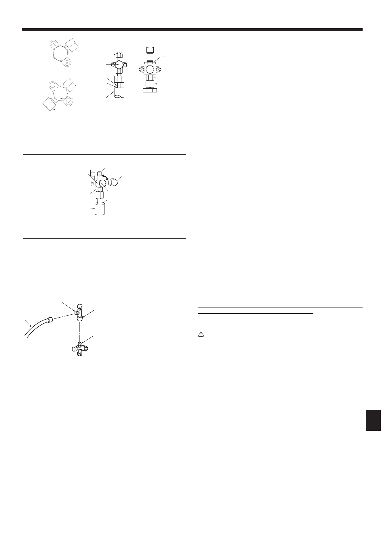
4.5. Stop valve opening method (Fig. 4-5)
1 Remove the cap and turn the valve rod counterclockwise as far as it will go with the
use of a 4 mm, 5/32 inch hexagonal wrench. Stop turning when it hits the stopper.
(ø6.35, 1/4 inch: Approximately 4.5 revolutions) (ø9.52, 3/8 inch: Approximately
10 revolutions)
2 Make sure that the stop valve is open completely, push in the handle and rotate
he cap back to its original position.
A Valve
B Unit side
C Operation section
D Cap
E Local pipe side
F Pipe cover
G Service port
H Wrench hole
Refrigerant pipes are protectively wrapped for A24-A42
• The pipes can be protectively wrapped up to a diameter of ø90 mm, 3-35/64 inch
before or after connecting the pipes. Cut out the knockout in the pipe cover follow-
ing the groove and wrap the pipes.
Pipe inlet gap for A24-A42
• Use putty or sealant to seal the pipe inlet around the pipes so that no gaps remain.
(If the gaps are not closed, noise may be emitted or water and dust will enter the
unit and breakdown may result.)
I Double spanner section
(Do not apply a spanner other than to this sec-
tion. Doing so would cause refrigerant leaks.)
J Seal section
(Seal the end of the heat insulation material at
the pipe connection section with whatever seal
material you have on hand so that water does
not inltrate the heat insulation material.)
K Handle
Precautions when using the charge valve (Fig. 4-6)
Do not tighten the service port too much when installing it, otherwise, the valve core
could be deformed and become loose, causing a gas leak.
After positioning section B in the desired direction, turn section
A
only and tighten it.
Do not further tighten sections A and B together after tightening section A.
Warning:
When opening or closing the valve below freezing temperatures, refrigerant
may spurt out from the gap between the valve stem and the valve body, result-
ing in injuries.
A
B
H
I
C
D
E
F
G
D
B
A
C
Fig. 4-4
D
G
B
A
I
F
E
J
H
Fig. 4-5
c
B
A
D
Fig. 4-6
Notes:
1. The gure to the left is an example only.
The stop valve shape, service port po-
sition, etc., may vary according to the
model.
2. Turn section A only.
(Do not further tighten sections A and
B together.)
C Charge hose
D Service port
A Stop valve <Liquid side>
B Stop valve <Gas side>
C Service port
D Open/Close section
E Local pipe
F Sealed, same way for gas side
G Pipe cover
H Do not use a wrench here.
Refrigerant leakage may result.
I Use 2 wrenches here.
en
BG79U896H14_01en.indd 6 2021/10/22 15:52:27
007
Loading ...
Loading ...
Loading ...