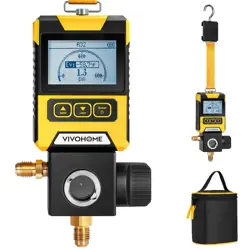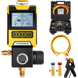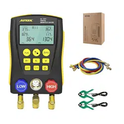
lm 120
DIGITAL MANIFOLD GAUGE
EN_V0
Please read the user manual carefully
and operate according to the regulations.
WARNING
USER
MANUAL

1. Overview.............................................................1
2. Safety rules and precautions.................................1
3. International electrical symbols.............................3
4. Product specifications..........................................3
5. Product Icon and description.................................4
6. Function instructions............................................5
6-1. Refrigerant filling and pressure inspection...........5
6-2. Vacuum operation.............................................8
6-3. Pressure Leak Test............................................9
7. Common problems..............................................10
7-1. Low battery power supply.................................10
7-2. Damaged refrigerant hose or valve stem............10
7-3. Failure of refrigerant filling...............................10
7-4. Potential leak points........................................10
8. Glossary............................................................11
CONTENT
The device, which has both the dry ball thermometer
and the wet bulb thermometer, is called the dry
humidimeter, which can be used to measure the relative
humidity in the atmosphere.
Black ball temperature: also called actual temperature,
it indicates the actual sensory temperature expressed by
temperature when a person or an object is combined with
radiant heat and convective heat in a radiant heat
environment.
The black ball temperature measured is generally
higher than the ambient temperature, which is the air
temperature.
◆ Relative humidity and absolute humidity
Absolute humidity: the mass of water vapor in a unit
volume of air is called the "absolute humidity" of air. It is a
representation of the physical quantity of atmospheric
dryness and humidity. It is usually expressed in grams of
water vapor contained in 1 cubic meter of air.
Relative humidity: the actual water vapor density in air
and the percentage of saturated water vapor density at the
same temperature are called the “relative humidity” of air.
The degree of dryness and humidity of the air is related
to the degree of saturation of water vapor contained in the
air, but it is not directly related to the absolute amount of
water vapor contained in the air.
◆ COP and EER
EER: the ratio of the cooling capacity to the effective
input power when the air conditioner performs a cooling
operation under rated conditions and specified conditions,
the value of which is expressed in W/W.
COP: under rated operating conditions (high
temperature) and specified conditions, when the air-
conditioning heat pump heating operation, the ratio of
heating and effective input power, the value of W/W.
13
Please read the user manual carefully
and operate according to the regulations.
WARNING

The degree of expansion of the expansion valve
(refrigerant charge) affects the degree of superheat. The
greater the degree of superheat, the smaller the opening of
the expansion valve can be determined (the refrigerant
charge is less).
◆ Sensible heat and latent heat
The amount of heat required to raise the water
temperature from 0 degrees to 100 degrees is sensible
heat, the water is heated to 100 degrees, and the hot water
becomes water vapor, but the temperature is still 100
degrees. The heat required for this process is called latent
heat.
◆ Gauge pressure and absolute pressure
Gauge pressure: Gauge pressure refers to the pipeline
pressure, refers to the pressure measured by pressure
gauges, vacuum gauges, U-shaped tubes, etc., also
known as relative pressure. The “table pressure” starts
with atmospheric pressure and the symbol is Pg.
Absolute pressure: The pressure directly acting on the
surface of a container or object is called "absolute
pressure", the absolute pressure value is absolute vacuum
as a starting point, the symbol is PABS (ABS is a subscript)
and the absolute pressure is atmospheric pressure +
gauge pressure.
At atmospheric pressure, the gauge pressure is 0 and
the absolute pressure is 1.013 bar.
◆ Dry bulb temperature, wet bulb temperature and
black ball temperature
Dry bulb temperature: the temperature measured by
ordinary thermometers.
Wet bulb temperature: a wet cloth is wrapped around
the thermometer, and the temperature indicates a drop due
to the evaporation of water. The temperature at this time is
called the wet-bulb temperature.
12
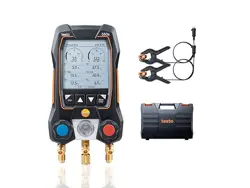
1. Overview
Intelligent electronic refrigerant group instrument is an
auxiliary instrument for the installation, testing and
maintenance of refrigeration equipment such as air
conditioners and cold storage. The instrument has double
pressure test, dual temperature test, digital readout, multi-
unit switching, multi-mode function and built-in refrigerant
database.
The instrument uses high-strength engineering plastics
and flexible non-slip silicone design, the whole machine is
solid and comfortable to hold. Built-in 32-bit digital
processing unit and high-precision data acquisition unit,
high data and stability. Large-size liquid crystal display,
LCD backlight support, data display clear and easy to read,
convenient light operation. Long-life valve switch, 1/4-inch
standard interface design to ensure that the instrument's
durability and versatility.
The instrument can measure double pressure (gauge
pressure) at the same time, as well as dual temperature
measurement, with automatic multi-unit pressure
conversion, automatic conversion of temperature Celsius /
Fahrenheit, to facilitate different needs. Built-in 89 kinds of
refrigerant pressure-evaporation temperature database,
also calculate the subcooling superheat, to facilitate direct
reading of operating process data. Also it tests percentage
of vacuum measurement; pressure leak measurement,
leak time speed record. It is deserved to have this multi-
functional, accurate and simply operated digital manifold
let you do the job right.
2. Safety rules and precautions
This manual includes the use of instrument instructions
and warnings for safe operation and maintenance. Failure
to use the meter in accordance with the manual may
damage the instrument. This instrument strictly follows the
1

IEC/EN61010-1 safety standards for design and
production.
1) The pressure measured by the digtal manifold
pressure tester is gauge pressure.
2) Pressure testing ranges from -101Kpa to 6Mpa (-
0.1bar to 60bar).
3) The limit pressure is 10 Mpa (100 bar).
4) The maximum operating pressure of standard hose
is 600 PSI ( approximate 4.13 Mpa, 41.3 bar ). The limit
pressure is 3000 PSI approximate 20.68 Mpa, 206.8 bar ).
5) Please confirm the rated pressure value of the tested
equipment before testing. Do not use it if it exceeds the
range of the instrument. If the packed hoses does not
match the pressure requirement, you can use suitable
replacements for testing.
6) Do not use and store the instrument in high
temperature, high humidity, flammable, explosive and
strong electromagnetic fields.
7) Please do not change the instrument internal circuit,
to avoid any damage of the instrument or danger occurring.
8) Please wear qualified protective equipment to
protect user during testing.
9) Please use the instrument in a well-ventilated
environment to prevent inhalation of toxic gases.
2
The port is equipped with a copper plug screw. It is
required to tighten it every time before or after operation.
- Check the refrigeration system's pipes and
connectors.
8. Glossary
◆ Saturation
The state of saturation is the coexistence of a
refrigerant in a liquid and gas state.
◆ Condensation temperature and evaporation
temperature
Condensation temperature: in the condenser, the
refrigerant is condensed by the high-temperature gaseous
refrigerant to the temperature of the liquid refrigerant, that
is, the saturation temperature under the condensing
pressure.
Evaporation temperature: in the evaporator, the
refrigerant evaporates from the liquid refrigerant to the
temperature of the gaseous refrigerant, that is, the
saturation temperature under the evaporation pressure.
◆ Degree of subcooling and superheat
Subcooling: condensing temperature - condensing
outlet temperature.
Superheat: evaporation outlet temperature -
evaporation temperature.
The lower subcooling can make the refrigeration
capacity of the system better. Adding subcooling circuit
and economizer in the refrigeration system is to increase
the subcooling for refrigerant increasing.
11
7. Common problems
7-1. Low battery power supply
The instruments has low power sign. When it is
displayed , it means the battery power is insufficient. At
this time, the battery should be replaced as required in
order to avoid affecting normal use.
7-2. Damaged refrigerant hose or
valve stem
Please check the pipe fittings and the hoses before
testing. Once any damage is found , please replace it
immediately to avoid improper use or any accident
occurring.
7-3. Failure of refrigerant filling
There is a valve core in the refrigerant inlet of the
refrigeration system. When connecting the instrument, pay
attention to the two terminals of the hoses. Connect one
terminal with a core to the refrigeration system, while
another terminal without a core to the instrument.
7-4. Potential leak points
- Every hose terminal comes with a nylon pad that is
limited a certain life of using. Over use or other situation
will make it defective, which result in leakage.
- The instrument refrigerant inlet (the middle port of the
instrument ) has a port with valve core , which is used to
vent the air in the hoes after connecting the refrigerant to
the instrument.
10
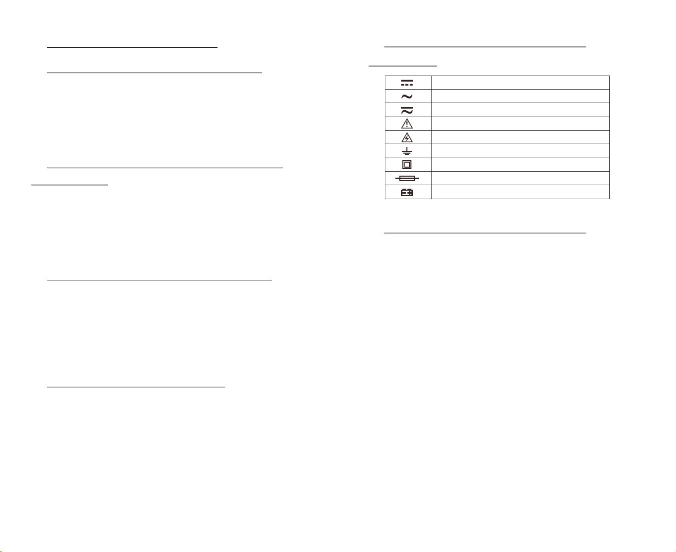
3. International electrical
symbols
4. Product specifications
Pressure test: gauge pressure
Pressure test unit: Kpa; Mpa; bar; inHg; PSI.
Pressure test range: 0 Kpa – 6000 Kpa
Pressure test resolution: 1 Kpa
Pressure test accuracy: +/- 0.5 %(FS)+ 5dgt
Pressure overload limit: 10000 Kpa (10 Mpa; 100 bar;)
Vacuum test: relative vacuum
Vacuum test unit: Kpa; Mpa; bar; inHg; PSI.
Vacuum test range: -101 Kpa – 0 Kpa
Vacuum test resolution: 1 Kpa
Temperature test unit: °C (Celsius), °F (Fahrenheit)
Temperature test range: -40°C–150°C (-40°F–302°F)
Temperature test resolution:
0.1°C (-40°C–99.9°C), 1°C (100°C–150°C)
0.1°F (-40°F–99.9°F), 1°F (100°F–302°F)
Temperature test accuracy: +/- 0.5 °C + 2dgt
+/- 0.9 °F + 2dgt
Built-in 89 kinds of refrigerant NIST:
◆ According to American NIST standard
DC
AC
DC/ AC
warning
dangerous voltage( electric shock)
earth
double insulation
fuse
battery
3
Power Supply: 4 X 1.5V (SIZE.AA / LR6)
Dimensions: 170*110* 50mm weight: 950g
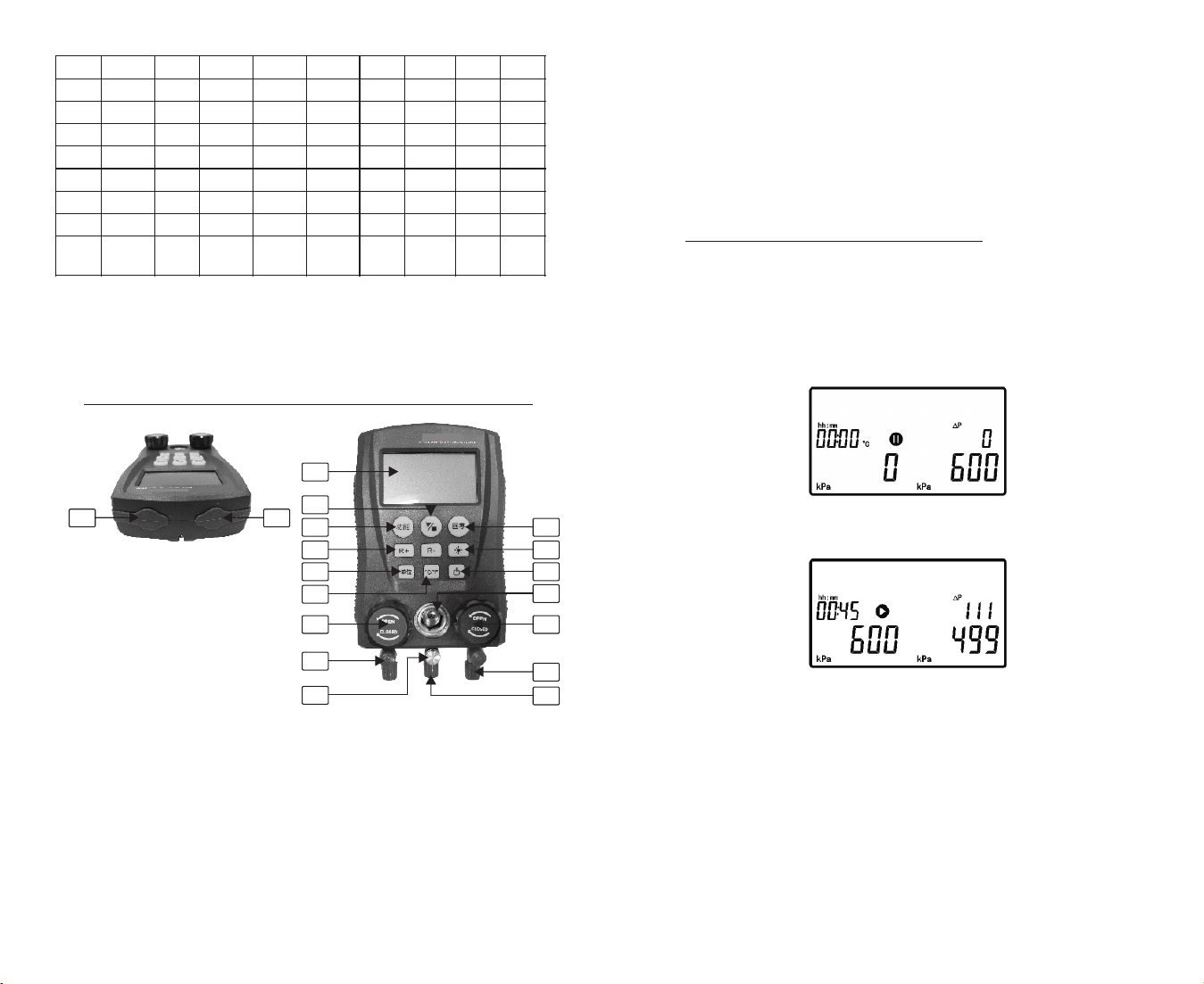
5. Product Icon and description
1) Clamp-on temperature probe socket
2) Clamp-on temperature probe socket
3) LCD display
4) Run/Stop button: In Leak Test Mode, Test Control
Button
5) Function button: test function mode switch button
6) R+/R-Refrigerant Type Selection Buttons: Switch to
select different types of working refrigerants
7) Unit button: pressure unit switch button
R11
R113
R114
R115
R116
R12
R123
R124
R125
R1270
R13
R134A
R14
R141B
R142B
R143A
R152A
R170
R21
R218
R22
R227EA
R23
R236EA
R245CA
R245FA
R290
R32
R401A
R401B
R401C
R402A
R402B
R403A
R403B
R404A
R405A
R406A
R407A
R407B
R407C
R407D
R407E
R408A
R409A
R409B
R41
R410A
R410B
R411A
R411B
R412A
R413A
R414A
R414B
R415A
R415B
R416A
R417A
R418A
R419A
R420A
R421A
R421B
R422A
R422B
R422C
R422D
R423A
R424A
R425A
R426A
R427A
R428A
R50
R500
R501
R502
R503
R504
R507A
R508A
R508B
R509A
R600
R600A
R717
R744
(Co2)
R1234
4
G. After the vacuum operation is completed, turn off the
blue valve and red valve, then shut the vacuum pump.
At this time, pressure leak test mode can be used to
check leakage in the system ( Please refer to 6-3. Pressure
Leak Test).
6-3. Pressure Leak Test
A. The instrument is power on with the blue and red
valves turned off.
B. Press the Function button to pressure leak test mode
shown as below. The current pressure value is displayed at
lower right corner of LCD.
C. Press the Run/Stop button to start the leak test, as
shown below:
At this time, the lower left corner records the initial
pressure value; the lower right corner shows the
instantaneous pressure value; the “ΔP” display area shows
the difference between initial pressure value and
instantaneous pressure value.
The time display area shows how long the leak test lasts
in the format of Hour : Minute (HH:MM). All the pressure
units on the screen are the same. You can switch different
pressure units by pressing the unit button.
9
2
1
1 1
1 0
9
1 4
5
6
7
1 3
3
1 6
1 5
8
4
1 2
1 7
1 8
6-2. Vacuum operation
A. Turn off the blue valve and red valve.
B. Power on the instrument. Then make sure if the LCD
displays vacuum test status as below picture. If not, press
the Function button to switch it.
C. Press the unit button to adjust the reading unit.
D. When the instrument is turned on, there may be 10
digits in the high and low pressure display area. At this
time, press the zero button long until it returns to zero.
E. Connect the instrument to the refrigeration system
according to the chart below. (pay attention to the direction
of the refrigerant flowing!!!!! ) (Connected clamp-on
temperature probes will not affect the operation..)
F. Turn on the blue valve and red valve, and start the
vacuum pump.
8
8) °C/°F button: temperature unit switch button
9) Zero button: pressure display zero button
10) Backlit button
11) Power button
12) Refrigerant observation window
13) Low pressure valve
14) High pressure valve
15) 1/4 inch low pressure inlet
16) 1/4 inch high pressure inlet
17) Pressure release valve
18) Refrigerant inlet/vacuum pump inlet
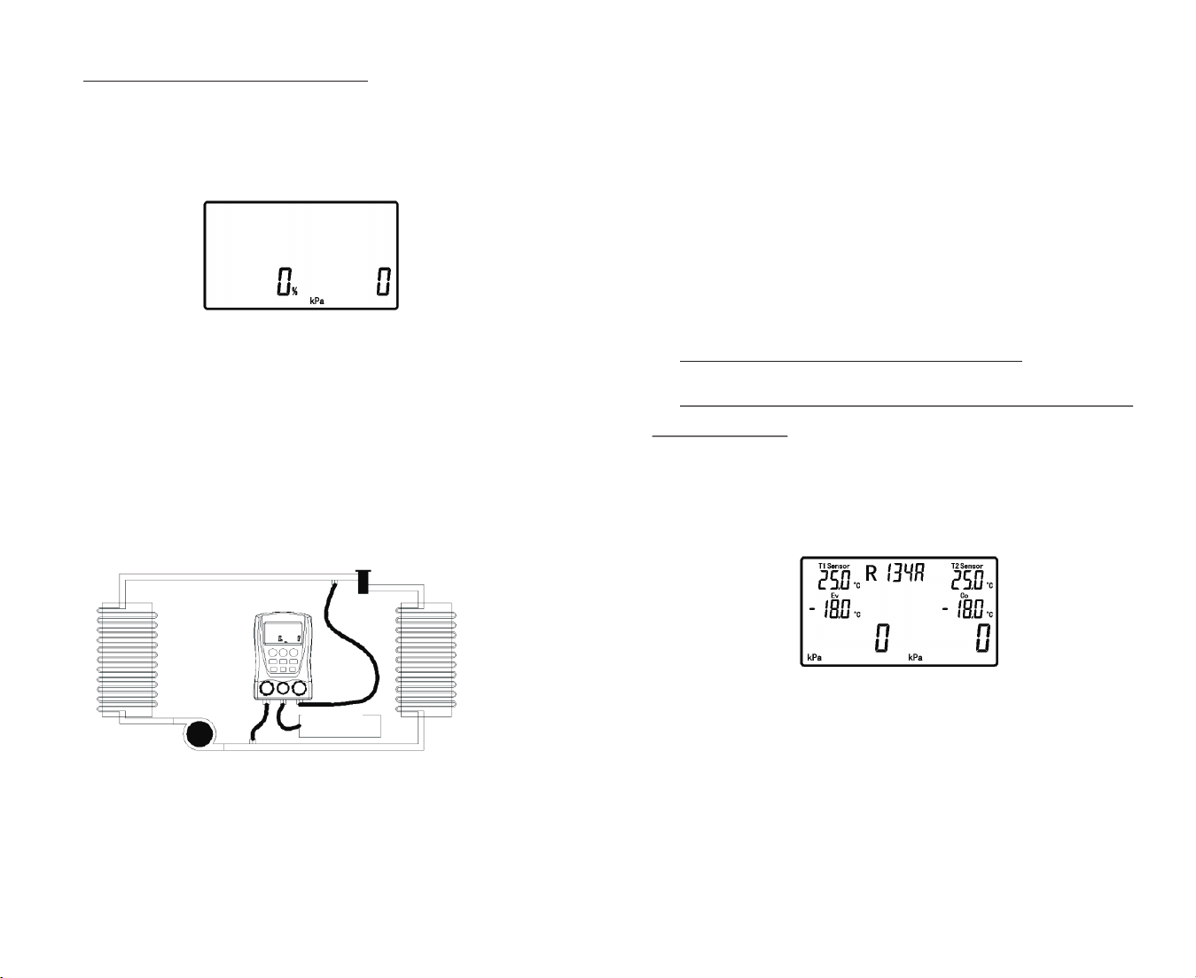
6. Function instructions
6-1. Refrigerant filling and pressure
inspection
A. Turn off the blue valve and red valve.
B. Power on the instrument. Then make sure if the LCD
displays pressure test status as below picture. If not, press
the Function button to switch it.
C. If the temperature probe accessories have been
connected to the instrument, the real-time temperature will
be displayed. If not, no display of it.
D. Press R+/ R- buttons , Unit button and °C/°F button
to select tested refrigerant and reading display
respectively.
E. When the instrument is turned on, there may be 10
digits in the high and low pressure display area. At this
time, press the zero button long until it returns to zero.
5
thermal expansion
valve
condenser
evaporator
compressor
vacuum pump
F. Connect the instrument to the refrigeration system
according to the chart below. (pay attention to the direction
of the refrigerant flowing!!!!! )
G. Turn on the refrigerant valve and gently press the
pressure release valve to vent the air in the connecting
hose.
H. When the refrigeration system stops, turn on the
high pressure valve (red valve) and fill with a certain
amount of refrigerant and then shut the valve quickly.
I. Run the refrigeration system, turn on the low
pressure valve (blue valve), and fill with the refrigerant into
the refrigeration system. Vacuum operation is required if it
is filled initially or in full with refrigerant. Refer to the
section on vacuum operation.
J. After the filling is completed, shut the low pressure
valve (blue valve) and refrigerant valve. Let the
refrigeration system running.
K. Shut down the refrigeration system, make sure all
valves are turned off , then disconnect the instrument
between refrigeration system and source. Do not remove
the high pressure valve connection until the pressure
drops to the safe point. Then turn off the instrument.
Note: The filling operation of different equipment or
refrigerants may vary. Please read carefully the relevant
specific operation requirements for filling operation, so as
to avoid damage to user or equipment caused by improper
operation! ! !
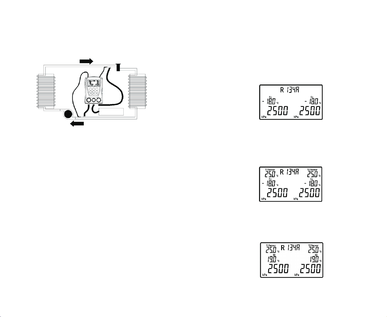
◆ The instrument can display the corresponding
Evaporation Temperature (EV) and Condensation
Temperature (CO) during the refrigerant pressure test, as
shown below:
◆ If the clamp-on temperature probes are connected to
the instrument, LCD will display the real-time temperature
in the spot T1 Sensor and T2 Sensor, as shown below.
Please make sure clamp-on temperature probes are
connected as step F and contacted fully to the refrigeration
pipes.
◆ The instrument can calculate the SH - Superheat
and SC - Subcooling as shown below as long as the tested
refrigerant is preset and clamp-on temperature probes are
connected well.
6
7
refrigerant
flowing direction
condenser
thermal expansion
valve
evaporator
refrigerant
compressor
refrigerant flowing direction