USER MANUAL
THANK
YOU!
Thank You for Purchasing from
Made in China
NOTE:
To continuously improve its products, reserves the right to
modify this information without prior notification.
For any questions regarding assembly, please watch the video on the
product page or contact our customer service. Our customer service will
Thank you for using products in your home!
Digital Vacuum Pressure
Manifold Gauge

About This Document...............................................1
Safety Instructions ......................................................1
Operating Environment ..........................................2
Product Description..................................................2
1. Parameter...........................................................................2
2. Functional Overview and Configuration
Differences.............................................................................3
3. Button Function.............................................................5
4. Icon Description............................................................5
Setting Before Use......................................................6
1. Unit of Measure ............................................................. 6
2. System Parameter ........................................................7
Measurement Mode ..................................................9
Operating Instructions............................................ 11
1. Pressure Temperature Inspection and
Refrigerant Filling ............................................................. 11
2. Pressure Leak Test...................................................... 13
3. Temperature ..................................................................14
4. AC ECG .............................................................................. 15
Maintenance ............................................................... 16
1. Cleaning the Instrument.........................................16
2. Keeping Connections Clean................................16
3. Changing Batteries.....................................................16
Available Refrigerants ............................................ 17
Warranty....................................................................... 18
USER MANUAL
HOW-TO
Digital Vacuum Pressure
Manifold Gauge
CONTENTS
Assembly is EASY!
WE WANT
YOU TO
ENJOY LIFE
AT
GO TO THE PRODUCT LISTING PAGE
FOR AN INSTRUCTIONAL VIDEO!
SECTION A
About This Document
The instruction manual is an integral part of the instrument. Please
read this documentation carefully and familiarize yourself with the
product before putting it to use.
Pay particular attention to the safety instructions and warning
advice in order to prevent injury and damage to the product.
Indicates a reminder or further description of a feature
Warning: Serious physical injury may occur.
Symbols and writing standards
1. Parameter
SECTION B
Safety Instructions
Do not operate the instrument if there are signs of damage to
the housing or hoses.
Do not perform contact measurements on non-insulated,
live parts.
Do not store the product with solvents. Do not use desiccants
on the instrument itself.
Dangers may also arise from the refrigeration systems being
measured or the measuring environment. Always note and
comply with the local safety regulations applicable to your
work area.
Dropping the instrument or subjecting it to comparable me-
chanical shock can break the filling tube and damage the con-
trol valve. To ensure safety, replace the filling tube with a new
one and check the condition of the instrument.
1.
2.
3.
4.
5.
SECTION C
Operating Environment
The instruments are digital refrigerant meters for the mainte-
nance and servicing of refrigeration systems and heat pumps.
They should only be operated by qualified or trained personnel.
The instruments are compatible with most non-corrosive
refrigerants, as well as water and glycol.
The instruments are not compatible with refrigerants contain-
ing ammonia.
The products must not be used in potentially explosive atmo-
spheres!
1.
2.
3.
4.
5.
Measurement target exceeding the range is displayed as “----”
The customer must provide two AAA batteries (not included).
1.
2.
SECTION D
Product Description
Pressure measurement range -14.5~800psi
Pressure display resolution 0.5psi
Pressure measurement accuracy ±0.5%FS
Pressure unit kPa, MPa, psi, inHg, bar, kg/cm²
Temperature measurement range -58°F~302°F (-50°C~150°C)
Temperature display resolution 0.18°F (0.1°C)
Temperature measurement
accuracy
±0.9°F (±0.5°C)
Temperature unit °F, °C
Operating temperature 14°F~122°F (-10°C~50°C)
1 2

This pressure manifold gauge series is available inthree different
configurations.
The functions and included components of each model are
described below.
2. Functional overview and configuration differences
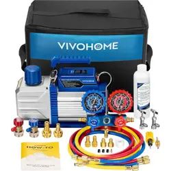
Product Name: VIVOHOME Digital Vacuum Pressure Manifold
Gauge
Functions (Gauge Only):
When used as a standalone digital vacuum pressure manifold
gauge, this model can:
1) Measure pressure parameters
– High-side pressure or low-side pressure
2) Measure refrigerant saturation temperature
– Evaporating temperature (low side) or
– Condensing temperature (high side)
SKU: VH1882
Product Name: VIVOHOME Digital Vacuum Pressure Manifold
Gauge with Temperature Clamp and Tubes
Functions (Complete Configuration):
This model includes the gauge, temperature clamp, refrigerant
hoses, and safety valves, and supports the following functions:
1) Measure pressure parameters
– High-side pressure or low-side pressure
2) Measure refrigerant saturation temperature
– Evaporating temperature or condensing temperature
3) Measure superheat or subcooling
4) Includes two refrigerant hoses:
Red hose: Used for measuring high-side or low-side pressure
Yellow hose: Used for refrigerant charging
5) Includes two anti-freeze safety valves:
One with 1/4" SAE External to 1/4" SAE Internal connections.
One with 1/4" SAE External to 5/16" SAE Internal connections.
Purpose: To ensure safe refrigerant flow and prevent accidental
contact with frozen components during operation.
SKU: VH1884
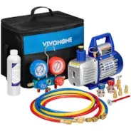
Product Name: VIVOHOME Digital Vacuum Pressure Manifold
Gauge with Temperature Clamp
Functions (Gauge + Temperature Clamp):
When used together with the temperature clamp, this model can:
1) Measure pressure parameters
– High-side pressure or low-side pressure
2) Measure refrigerant saturation temperature
– Evaporating temperature or condensing temperature
3) Measure superheat or subcooling
– Calculated based on pressure readings and temperature clamp
data
SKU: VH1883
3 4
5 6
Arrow Key
Change of refrigerant (SH/SC
Measuring interface)
Other functions: follow the
on-screen prompts
1.
2.
3.
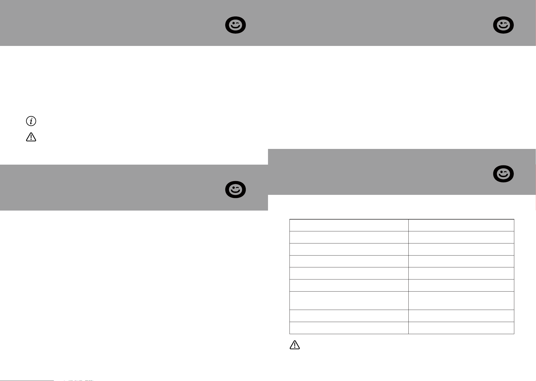
3. Button function
Pressure zeroing should be performed when the instru-
ment is not connected to the target system and the instru-
ment measurement interface is connected to the
atmosphere. Incorrect zeroing will lead to inaccurate mea-
surements. Following the correct method to re-zero will
restore normal operation.
Press (1 second) Long Press (3 seconds)
4. Icon description
Temperature probe connected
Auto Power Off
Battery level
Display when the battery is nearly depleted
and should be replaced as soon as possible.
Pressure zeroing
Arrow Key
Change of refrigerant
(SH/SC Measuring interface)
Other functions: follow the
on-screen prompts
1.
2.
3.
Turn on the backlight
Turn on the device
Open the Functions menu
Confirm your selection
1.
2.
3.
Turn off the device
SECTION E
Setting Before Use
The unit of measure has a memory function and does not need to
be reset after switching on or off. For user convenience, the unit
setting option is located on the first page of the menu.
Press the [ ]/[ ] key to select in the
Pressure Unit menu and press the
[Enter] key to confirm.
Press the [ ]/[ ] key to select in the
Temperature Unit menu and press the
[Enter] key to confirm.
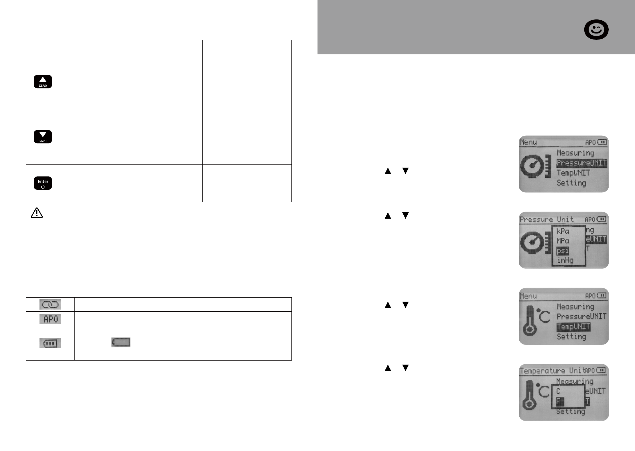
1. Unit of measure
Press the [Enter] key to open the menu.
Press the [ ]/[ ]key to select Pressure
Unit and press the [Enter] key to
confirm.
Set the pressure unit
Press the [ ]/[ ] key to select Temp
Unit and press the [Enter] key to
confirm.
Set the temperature unit
7 8
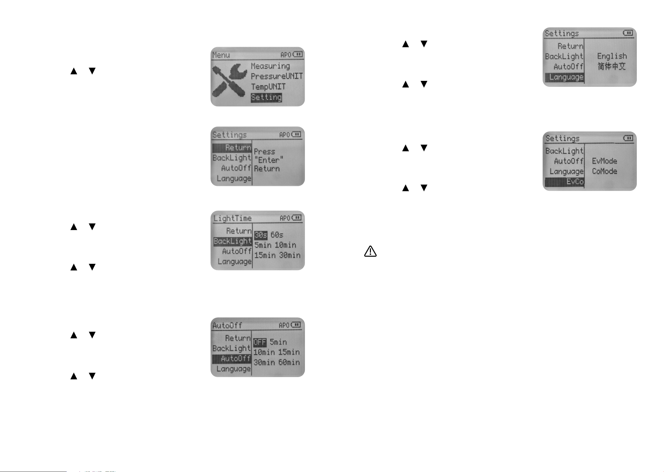
2. System parameter
Press the [Enter] key to open the menu.
Press the [ ]/[ ] key to select Setting
and press the [Enter] key to confirm.
The instrument enters the second page
of the Setting menu.
Available settings include:
BackLight Time
AutoOff Time
Language
Set the backlight time
Press the [ ]/[ ] key to select the
backlight and press the [Enter] key to
activate the Setting options.
Press the [ ]/[ ] key to select the
Setting option and press the [Enter]
key to confirm.
Press the [ ]/[ ] key to select the
Auto Off and press the [Enter] key to
activate the Setting options.
Press the [ ]/[ ]key to select the
Setting option and press the [Enter]
key to confirm.
Set the Auto-off time
Press the [ ]/[ ] key to select the
Language and press the [Enter] key to
activate the setting options.
Press the [ ]/[ ] key to select the
Setting option and press the [Enter]
key to confirm.
Highlights of EvCo setup options
This setting option is the EvMode by default, and the dif-
ferences between the two setting options are as follows:
EvMode: The instrument displays the evaporation satura-
tion temperature of the refrigerant and automatically cal-
culates the superheat after connecting the temperature
probe.
CoMode: The instrument displays the condensation satura-
tion temperature of the refrigerant and automatically cal-
culates the subcooling after connecting the temperature
probe.
Set the language
Press the [ ]/[ ]key to select the EvCo
and press the [Enter] key to activate
the setting options.
Press the [ ]/[ ] key to select the
Setting option and press the [Enter]
key to confirm.
Set the service point
9 10
SECTION F
Measurement Mode
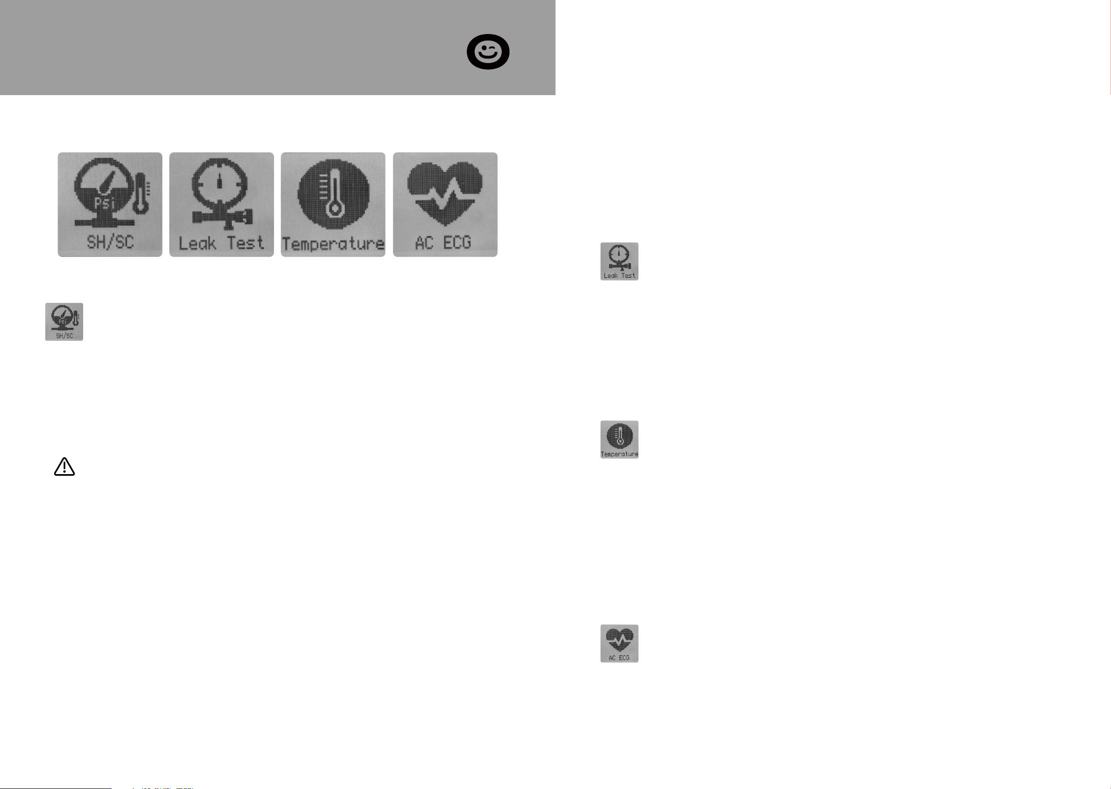
The instrument has 5 measurement modes:
An NTC temperature probe can be connected to measure
the pipe temperature and automatically calculate the degree
of superheat or subcooling.
Whether the instrument displays evaporating/condensing
temperature and calculates superheat or subcooling is deter-
mined by the EvCo setting, as detailed in section E.
Superheat Measurement: Hand-tighten the low-side hose to
the suction line service port. Attach the pipe clamp to the
suction line between the evaporator and the compressor,
ensuring it is positioned at least 6 inches away from the com-
pressor.
SH/SC Leak Test Temperature AC ECG
SH/SC
High pressure or Low pressure
Refrigerant evaporating or condensing temperatures
Temperature of suction line or Temperature of liquid line
Superheat or Subcooling
This mode measures the following system parameters::
1.
2.
3.
4.
Subcooling Measurement: Hand-tighten the high-side hose
to the liquid line service port. Attach the pipe clamp to the
liquid line between the condenser and the expansion valve
(TXV), positioning it as close to the service port as possible.
Stabilization Time: After starting the system or making any
system adjustments, allow the system to operate for at least
15 minutes before charging by superheat or subcooling to
ensure stable operating conditions.
Leak Test
Initial pressure
Current pressure
Test time
Differential pressure
This mode measures the following values of the system:
1.
2.
3.
4.
Temperature
This mode provides dual-temperature and temperature-difference
measurement. One channel (via the external probe) measures the
outdoor temperature, while the other (via the built-in sensor) mea-
sures the indoor temperature. The instrument calculates the
indoor-outdoor temperature difference, which helps quantify the
heating or cooling efficiency of the air conditioning system.
AC ECG:
This mode uses a curve-generation algorithm to visualize compres-
sor pressure pulsation as an ECG-like waveform. It can adjust the
display scale for different amplitude levels to accommodate vari-
ous operating conditions of the air conditioning system.
11 12
Wear protective goggles and safety gloves.
Comply with the permissible measuring range (-14.5 to 800 psi)
Before each measurement, check the refrigerant hoses are
intact and connected properly.
Before applying pressure to the instrument: Be sure to secure
the instrument to prevent it from falling.
1.
2.
3.
4.
SECTION G
Operating Instructions
WARNING
Risk of injury caused by refrigerant that is under high pressure, hot,
cold or toxic!
The above precautions cannot anticipate the complexities of the
actual premises and therefore cannot completely prevent acciden-
tal injuries from occurring, so please be proactive in identifying
potential hazards and comply with local regulations and standards.
Please take precautions for your safety!
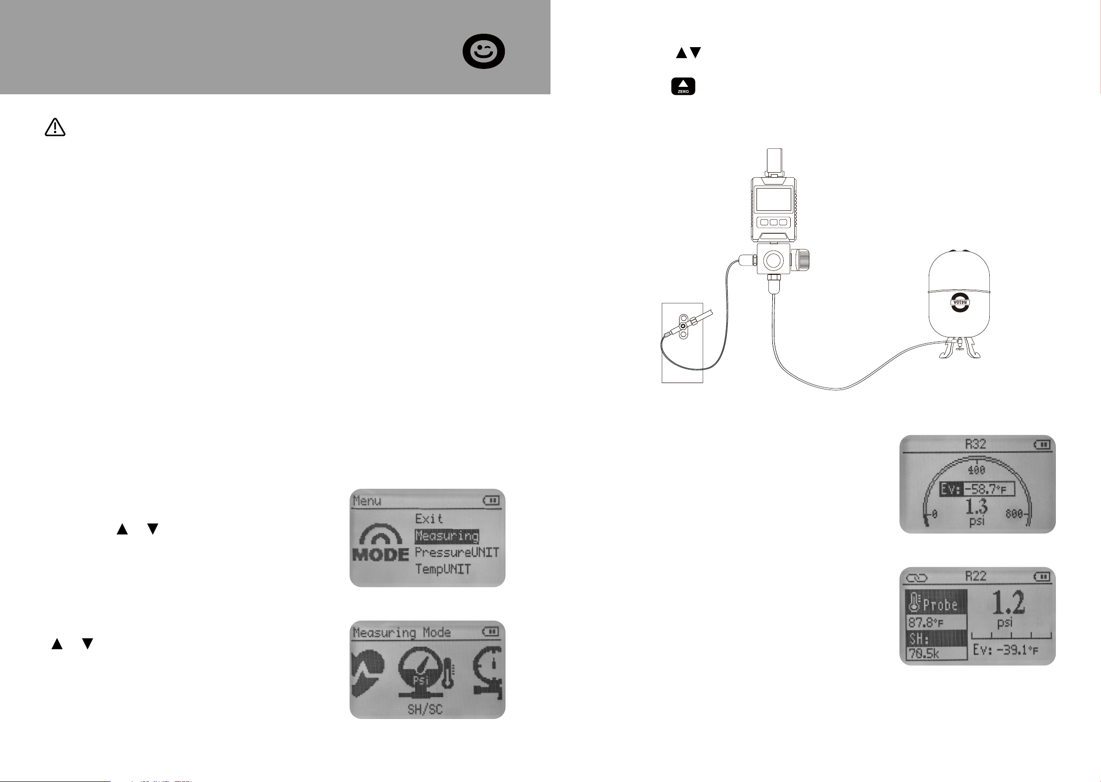
1. Pressure temperature inspection and Refrigerant filling
Press the [Enter] key to open the menu.
Press the [ ]/[ ]key to select Measur-
ing press the [Enter] key to confirm.
Enter the Measuring menu, press the
[ ]/[ ] button to select SH/SC, and
press the [Enter] button to confirm.
Without a temperature probe
connected, the instrument only dis-
plays the measured pressure and satu-
ration temperature parameters.
Connecting the temperature probe to
display more measurement parameters.
Short press to select the correctre frigerant.
Keep the instrument connector connected to the atmosphere,
long press to zero the pressure.
Connect the refrigerant hose to the target system to begin testing
or filling.
High pressure or Low pressure
Refrigerant evaporating or conden-
sation temperatures
Temperature of suction line or
Temperature of liquid line
Superheat or Subcooling
1.
2.
3.
4.
13 14
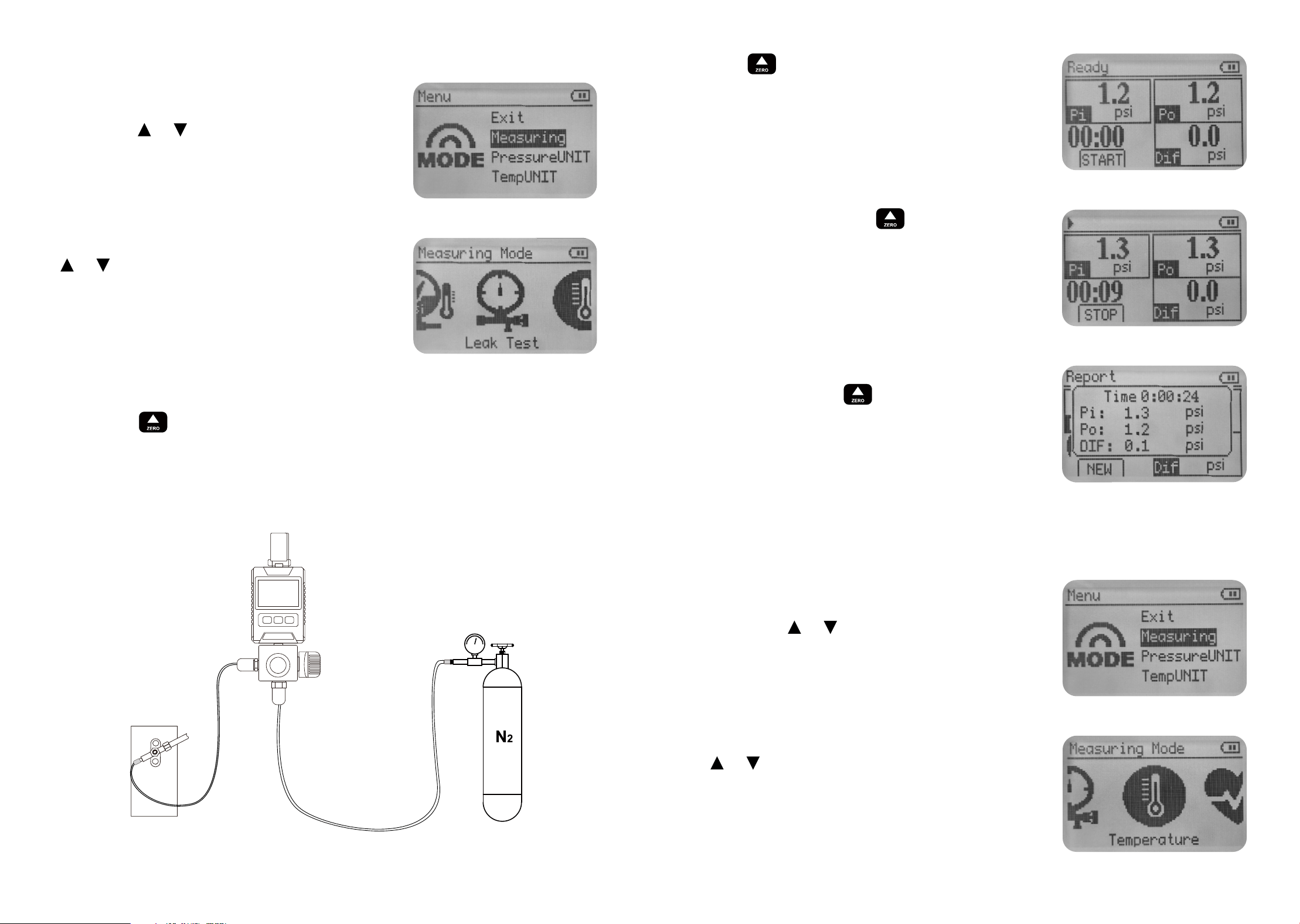
2. Pressure leak test
Press the [Enter] key to open the menu
Press the [ ]/[ ] key to select Measur-
ing press the [Enter] key to confirm.
Keep the instrument connector connected to the atmosphere,
long press to zero the pressure. During the pressure holding
test, the pressure value cannot be automatically reset to zero.
Connect the refrigerant hose to the target system and the yellow-
fluoride hose to the N2 source.
Enter the Measuring menu, press the
[ ]/[ ]button to select Leak Test, and
press the [Enter] button to confirm.
Press key to start the leak test.
During the test, press key to stop
the leak test.
After stopping, the test result is dis-
played and press key to start a new
test.
3. Temperature
Press the [Enter] key to open the menu.
Press the [ ]/[ ]key to select Measur-
ing press the [Enter] key to confirm.
Enter the Measuring menu, press the
[ ]/[ ]button to select Temperature,
and press the [Enter] button to con-
firm.
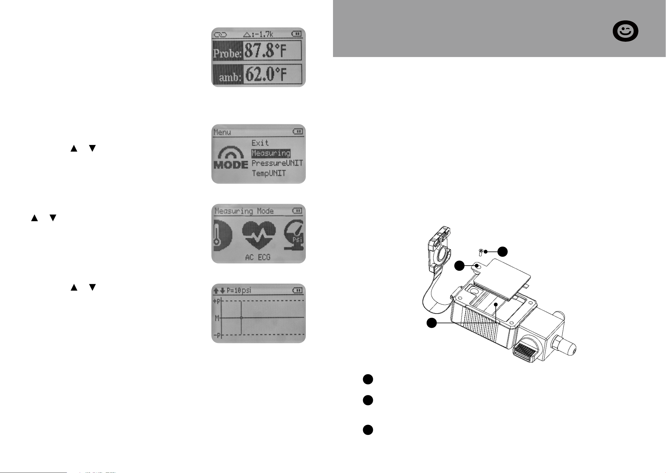
The instrument displays two-way tem-
perature and temperature difference.
4. AC ECG
Press the [Enter] key to open the menu.
Press the [ ]/[ ] key to select Measur-
ing press the [Enter] key to confirm.
Enter the Measuring menu, press the
[ ]/[ ] button to select AC ECG, and
press the [Enter] button to confirm.
Press the [ ]/[ ] keys to select the
appropriate display amplitude to allow
the screen to maximize the display of
the complete pressure fluctuation
curve.
15 16
SECTION H
Maintenance
- Do not use any aggressive cleaning agents or solvents! Mild
household cleaning agents and soap suds may be used.
- Carefully blow out oil residues in the valve block using
compressed air
- Clean interface bolts with a damp cloth as needed.
1. Cleaning the instrument
Promptly store the instrument in the carrying case after use to
prevent dust from entering through the hoses.
Loosen the fixing screws of the battery compartment cover.
Snap open the battery compartment cover along the groove at
the top of the compartment.
Remove the spent batteries and insert new ones into the bat-
tery compartment. Observe the correct polarity (+/-).
2. Keeping connections clean
3. Changing batteries
3
2
1
1
2
3
SECTION J
Warranty
The VIVOHOME warranty program is our commitment to you.
We are committed to providing you with a high-quality product
that meets your needs and expectations. To demonstrate our
confidence in the durability and performance of our products,
we offer the following warranty.
This warranty applies to all orders, purchases, or use of products
sold only by VIVOHOME and is valid for 1 year from the purchase
date. Please note, this warranty only covers the original order. If
a replacement is provided within the warranty period, it does
not extend the warranty.
WARRANTY COVERAGE
Loss of parts during use.
Normal wear and tear of products or parts.
Incorrect installation (e.g., using the wrong voltage) or improp-
er assembly.
Overloading the product’s bearing capacity.
Usage in extremely harsh conditions.
Improper cleaning or lack of maintenance.
Damage resulting from unintended use of the product.
Damage resulting from unauthorized modifications or service.
Indirect losses or damages related to the product.
This warranty applies to all orders, purchases, or use of products
sold only by VIVOHOME and is valid for 1 year from the purchase
date. Please note, this warranty only covers the original order. If
a replacement is provided within the warranty period, it does
not extend the warranty.
WARRANTY EXCLUSIONS
●
●
●
●
●
●
●
●
●
SECTION I
Available Refrigerants
US NIST standard data for 88 refrigerants
R113 R114 R115 R116 R12 R123 R1233ZD
R1234ZE R1234YF R124 R125 R13 R134A R14
R141b R143A R152A R170 R22 R227EA R23
R236FA R245FA R290 R32 R401A R401b R401C
R402A R402b R403b R404A R406A R407A R407b
R407C R407D R407F R408A R409A R410A R410b
R412A R413A R414A R414B R416A R417A R417C
R420A R421A R421b R422A R422b R422C R422d
R424A R426A R427A R428A R429A R433B R434A
R436A R437A R438A R441A R443A R448A R449A
R450A R452A R452b R453A R454A R454b R455A
R458A R500 R502 R503 R507A R508A R508b
R514A R600 R600A R601A / / /
17 18

VIVOHOME will provide technical support, replacement, refund,
or other solutions based on the issue’s specifics. If you wish to
return the original package for any reason, please contact us for
confirmation before initiating the return. You can expect a
response within 48 hours.
Thank you for choosing VIVOHOME. We are dedicated to ensur-
ing your satisfaction and the quality of your purchase. If you
have any questions or need further assistance, please don’t hesi-
tate to reach out to our customer service team.
If you encounter any defects affecting the product’s functional-
ity or if the product fails and cannot be repaired during the
warranty period, please reach out to our customer service team
via email, Amazon, or our app’s messaging service at your earli-
est convenience. To expedite your claim, kindly include:
HOW TO MAKE A WARRANTY CLAIM
Order number
Photos and/or videos illustrating the issue
A detailed description of the problem
●
●
●
SECTION J
Warranty
19