
1
For Customer Service Call 1-888-996-2729
© 2016 Escalade S por t s
1-88 8 - 9 9 6 - 2 7 2 9
F AX: 1-866-873-3535
gameroom@escaladesports.com
W e strive to ensure that our produc t s are of the highest quality
and free of manufacturing defec t s or missing p ar t s. Howeve r , if
you have any problems with your new product,
DO NOT RETURN IT T O THE S T OR E ,
please contact us toll free @:
Or w r i t e t o :
Escalade Sport s
Customer Service Departmen t
P .O. B o x 88 9
Evan sville I N 4770 6
When con t ac ting Escalade S por t s please provide your model numbe r , date code (i f
appli cable ), and pa rt nu mbe r i f reque sting a repla c e men t pa rt. The s e nu mbe rs a re
lo c a ted on the p rodu ct, pa ckaging , and in thi s owne rs manual .
Y our Model Number :
Please have your model number when inquiring about parts.
Date Code:
All Rights Reserved
Purchase Date:
PLEASE RETAIN THIS INSTRUCTION MANUAL FOR FUTURE REFERENCE
M01483W
2-M01483W- -GR
IMPORTANT! READ EACH STEP
IN THIS MANUAL BEFORE YOU
BEGIN THE ASSEMBLY.
TWO (2) ADU L TS ARE REQUIRED T O ASSEMBLE
THIS ATOMIC SLAM DUNK PC BACKBOARD
DOUBLE SHOOTOUT
RE A D A N D FOLL O W A L L ASSE M B L Y , OP E R A TIO N , A N D
S A FE T Y I N S T R U C TI O N S C A R E F U L L Y . A T L E A S T T W O
ADULTS ARE NEEDED TO PUT THIS BASKETBALL
SHOOTOUT TOGETHER.
2
For Customer Service Call 1-888-996-2729
© 2016 Escalade S por t s
All Rights Reserved
Tools Needed:
Make sure you understand the following tips before you begin to assemble your
basketball shootout.
1.This game (with Mechanical Scoring Arm) can be played outdoors in dry weather
- but must be stored indoors.
2.Tighten hardware as instructed.
3.Do not over tighten hardware,as you could crush the tubing.
4.Some drawings or images in this manual may not look exactly like your product.
5.To prevent damage to the electronics or to your wall, do not place this unit any closer
than six inches from the wall.
!
WARNING:
1) Do not mix old and new batteries.
2) Do not mix alkaline, standard (carbon zinc), or rechargeable (ni-cad, ni-mh, etc.) batteries.
3) Do not dispose of batteries in fire, batteries may explode or leak.
Allen Wrench (provided)
Wrench (provided)
Phillips Screwdriver
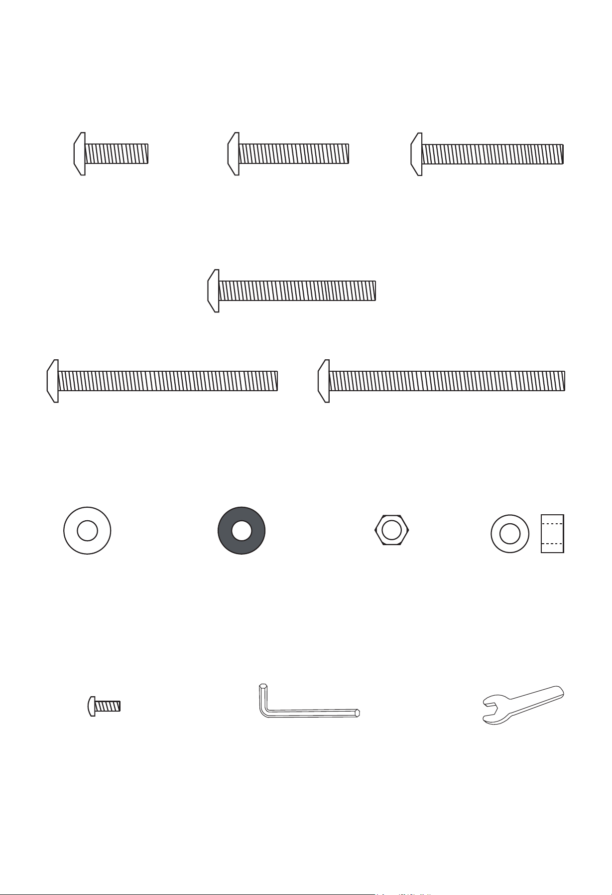
H1 - M6 x 20mm
Allen Head Bolt
(16 pc)
H7 - M6
Flat Washer
(70 pcs)
H9 - M6
Lock Nut
(43 pcs)
H10 - Plastic
Bushing
(8 pcs)
H2 - M6 x 35mm
Allen Head Bolt
(1 pc)
H3 - M6 x 45mm
Allen Head Bolt
(2 pcs)
3
For Customer Service Call 1-888-996-2729
© 2016 Escalade S por t s
All Rights Reserved
HARDWARE IDENTIFIER
(To Scale)
(Not to Scale)
H5 - M6 x 70mm
Allen Head Bolt
(6 pcs)
H6 - M6 x 75mm
Allen Head Bolt
(8 pcs)
H8- M6
Plastic Flat
Washer (14 pcs)
(Not to Scale)
H11 - 3.5 x 8mm
Phillips Head Bolt
(4 pcs)
T1 - Allen Wrench
(1 pc)
T2 - Wrench
(1 pc)
(Packed in with Scorer Box)
H4 - M6 x 50mm Allen Head Bolt (10 pcs)
4
For Customer Service Call 1-888-996-2729
© 2016 Escalade Sports
All RIghts Reserved.
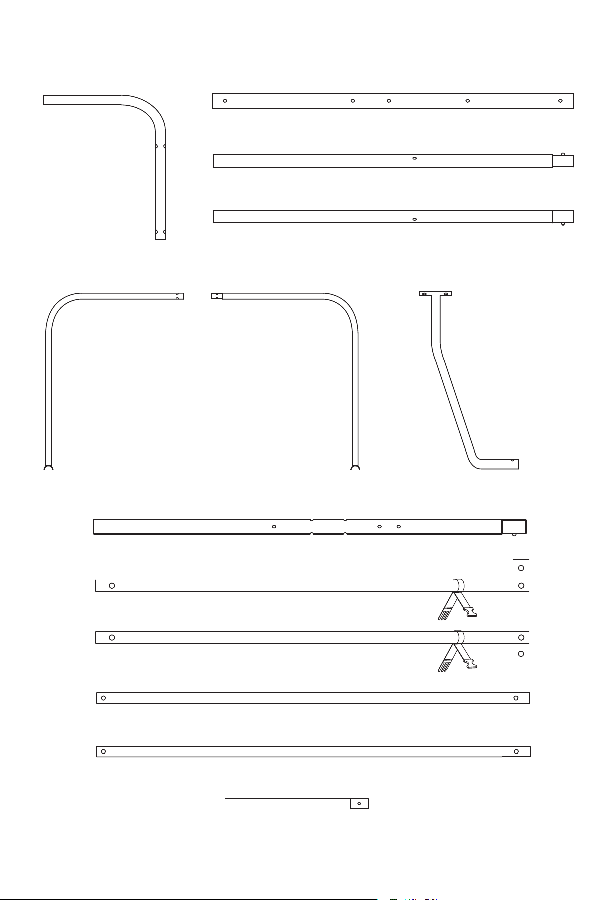
PARTS IDENTIFIER (Not to Scale)
P1 - Upper
Tube (2)
P2 - Middle Back Upright Tube (2)
P3 - Left Lower Back Upright Tube (1)
P4 - Right Lower Back Upright Tube (1)
P5 - Left Back
Bottom Support
Tube (1)
P6 - Right Back
Bottom Support
Tube (1)
P7 - Front
Support Tube (2)
P8 - Front Upright Tube (2)
P9 - Left Top Connect Tube (1)
P10 - Right Top Connect Tube (1)
P11 - Bottom Connect Tube (2)
P12 - Connect Tube (4)
P13 - Base Upright Tube (2)
5
For Customer Service Call 1-888-996-2729
© 2016 Escalade Sports
All RIghts Reserved.
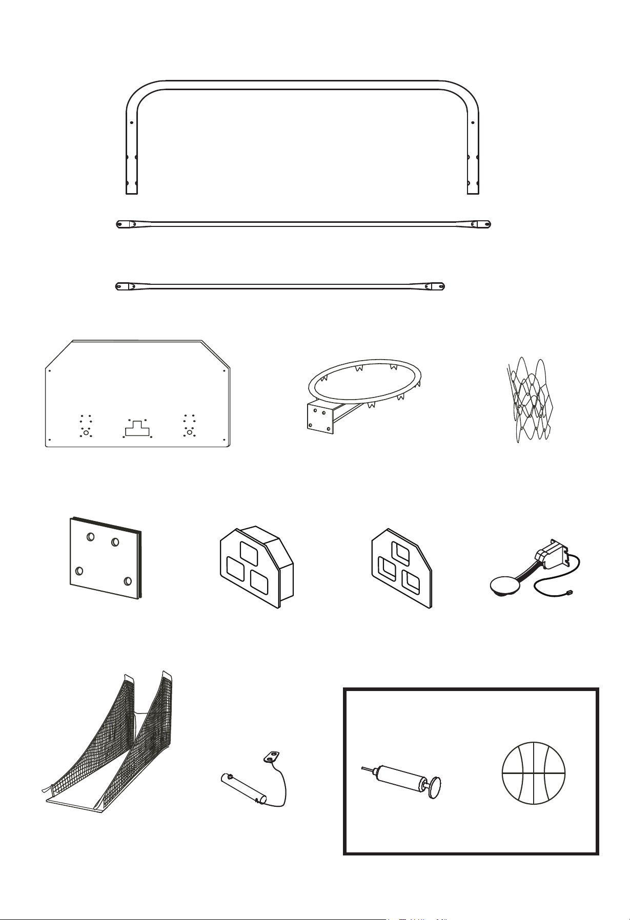
PARTS IDENTIFIER (Not to Scale)
P14 - Front U-Tube (1)
P15 - Long Support Tube (3)
P16 - Short Support Tube (2)
P17 - PC Backboard (1)
P19 - Rim Net (2)
P18 - Rim (2)
P20 - Rim Support
Plate (2)
P21 - Electronic
Scorer Display (1)
P23 - Mechanical
Scoring Arm (2)
P22 - Electronic
Scorer Face
Plate (1)
P24 - Ramp Chute (1)
P25 - Locking
Pin (2)
A2 - Basketball
(4)
A1 - Air Pump
with Needle (1)
ACCESORY IDENTIFIER
(Not to Scale)
6
For Customer Service Call 1-888-996-2729
© 2016 Escalade Sports
All RIghts Reserved.
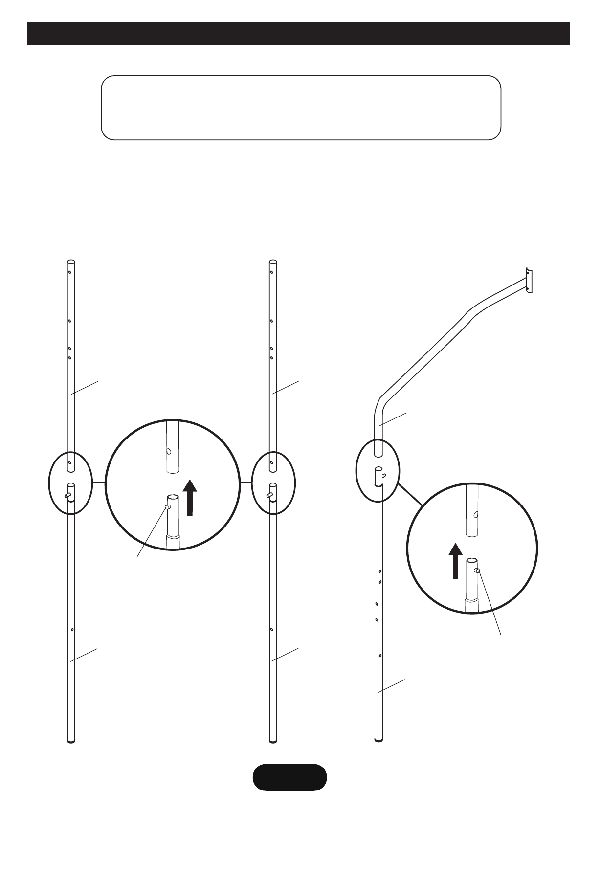
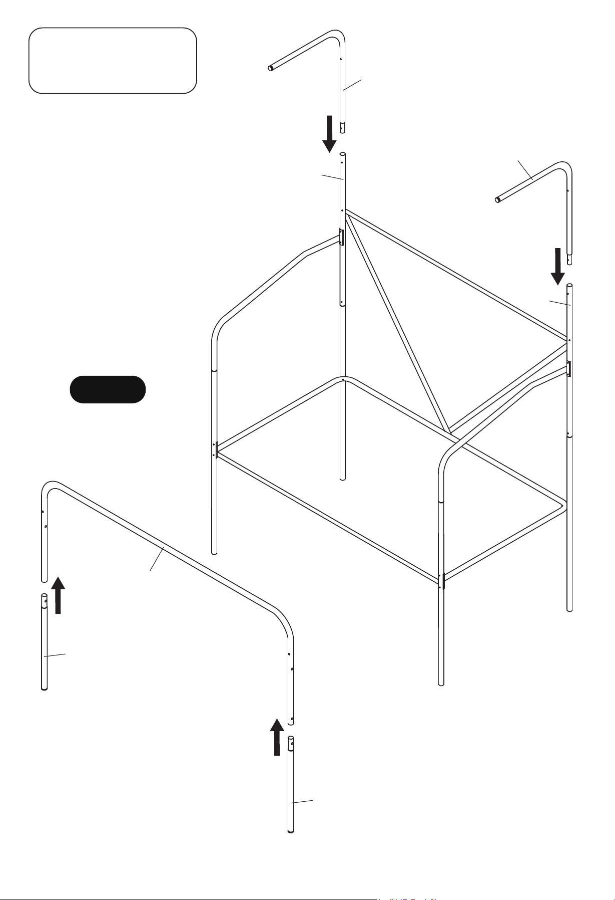
STEP 1
PARTS REQUIRED:
2 pcs - P2 Middle Back Upright Tube 2 pcs - P7 Front Support Tube
1 pc - P3 Left Lower Back Upright Tube 2 pcs - P8 Front Upright Tube
1 pc - P4 Right Lower Back Upright Tube
Connect P3 - Left and P4 - Right Lower Back Upright Tube to P2 - Middle Back Upright Tube using Spring
Lock as shown in FIGURE 1.
Connect P8 - Front Upright Tube to P7 - Front Support Tube using Spring Lock as shown in FIGURE 1.
Remove all the parts from the box and verify that you have all of the listed parts as shown on the Parts List.
FIGURE 1
Spring Lock
Spring Lock
P2
P2
P3
P4
P8
P7
X2
7
For Customer Service Call 1-888-996-2729
© 2016 Escalade Sports
All RIghts Reserved.
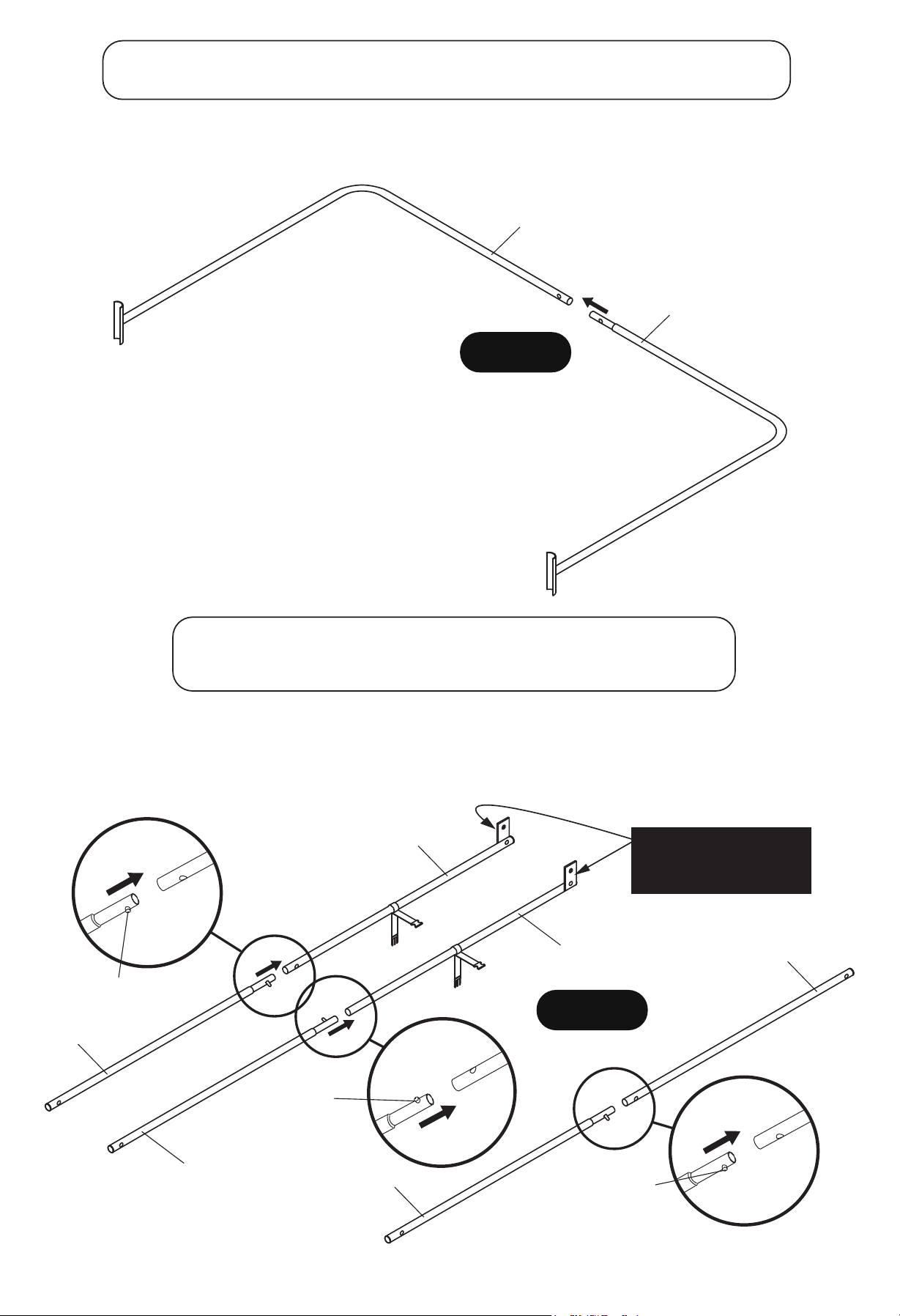
STEP 2
PARTS REQUIRED:
1 pc - P5 Left Back Bottom Support Tube 1 pc - P6 Right Back Bottom Support Tube
Slide P6 - Right Back Bottom Support Tube to P5 - Left Back Bottom Support Tube as shown in FIGURE 2.
FIGURE 2
P5
P6
STEP 3
PARTS REQUIRED:
1 pc - P9 Left Top Connect Tube 2 pcs - P11 Bottom Connect Tube
1 pc - P10 Right Top Connect Tube 4 pcs - P12 Connect Tube
Connect P12 - Connect Tubes to P9 - Left and P10 - Right Top Connect Tube using Spring Lock as shown
in FIGURE 3.
Connect P12 - Connect Tubes to P11 - Bottom Connect Tube using Spring Lock as shown in FIGURE 3.
FIGURE 3
P12
P12
P12
P9
P10
P11
X2
Spring Lock
Spring
Lock
Spring
Lock
NOTE: Each metal tab
face outside as per
diagram.
8
For Customer Service Call 1-888-996-2729
© 2016 Escalade Sports
All RIghts Reserved.
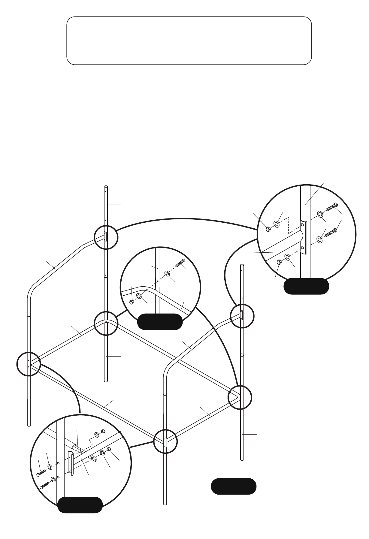
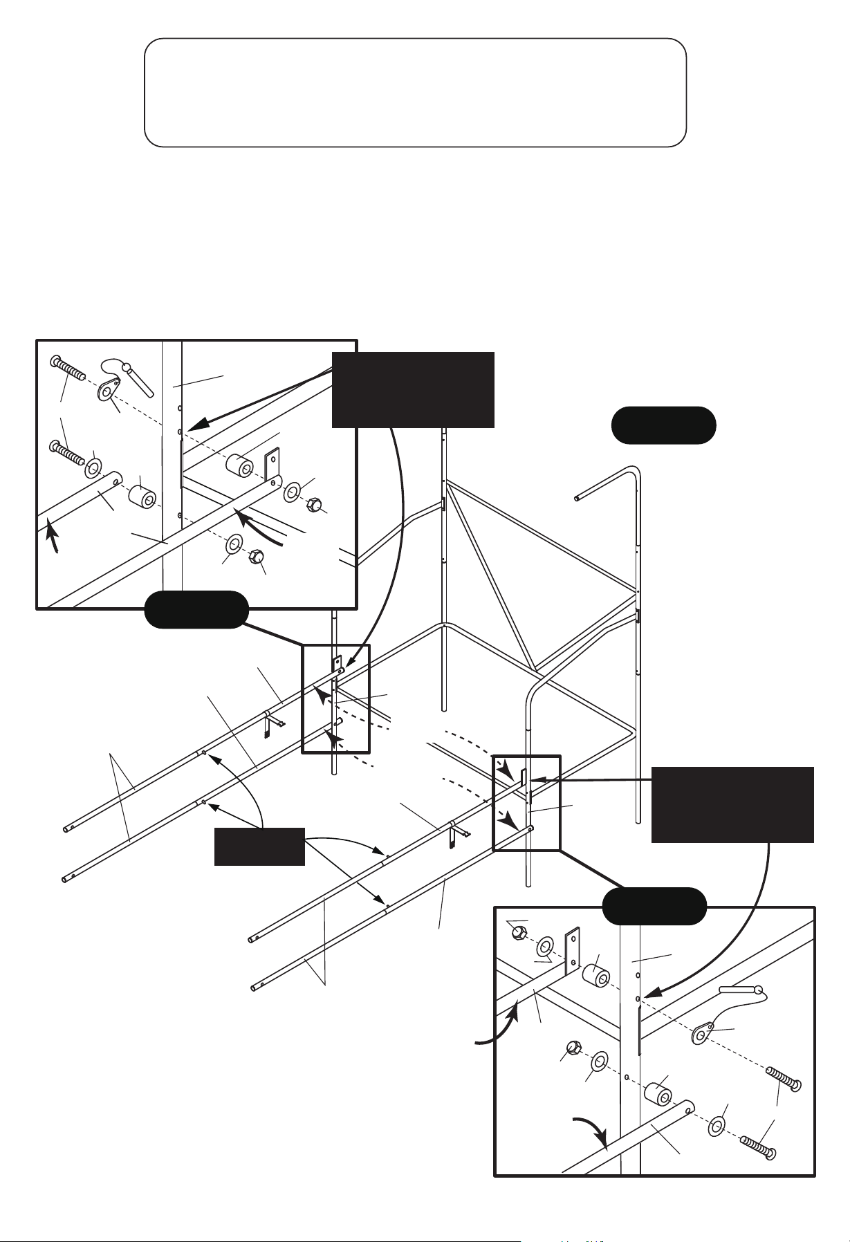
STEP 4
PARTS REQUIRED:
8 pcs - H4 M6 x 50 mm Allen Head Bolt 1 pc - P15 Long Support Tube
2 pcs - H5 M6 x 70 mm Allen Head Bolt 1 pc - T1 Allen Wrench
20 pcs - H7 Flat Washer 1 pc - T2 Wrench
10 pcs - H9 Lock Nut
Attach P5/P6 - Back Bottom Support Tube to P3/P4 Lower Back Upright Tube using H5 Bolts, H7 Washers and
H9 Lock Nuts as shown in FIGURE 4 and DETAIL A. Do not tighten H5 Bolts on this step.
Attach P5/P6 - Back Bottom Support Tube to P8 Front Upright Tubes and P15 Long Support Tube using H4 Bolts,
H7 Washers and H9 Lock Nuts as shown in FIGURE 4 and DETAIL B.
Do not tighten H4 Bolts on this step.
Attach P7 - Front Support Tubes to P2 Middle Back Upright Tubes using H4 Bolts, H7 Washers and H9 Lock Nuts
as shown in FIGURE 4 and DETAIL C.
Use T1 Allen Wrench and T2 Wrench to tighten all Bolts and Nuts.
FIGURE 4
P2
P2
P4
P3
P8
P8
P7
P7
P15
P5
P6
DETAIL A
DETAIL C
DETAIL B
H5
H7
H7
H9
P5/P6
P3/P4
H4
H7
H7
H7
H9
H9
P2
P7
H4
P5/P6
P15
H7
H7
H9
9
For Customer Service Call 1-888-996-2729
© 2016 Escalade Sports
All RIghts Reserved.
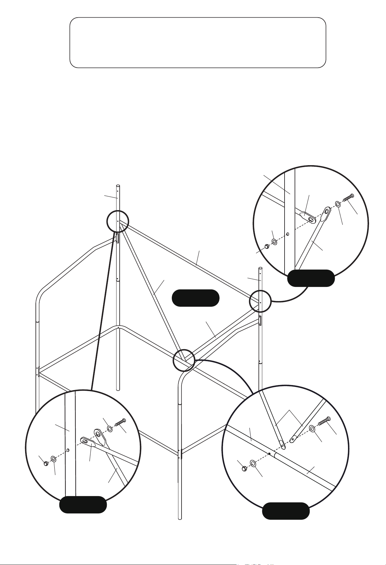
STEP 5
PARTS REQUIRED:
1 pc - H2 M6 x 35 mm Allen Head Bolt 1 pc - P15 Long Support Tube
2 pcs - H4 M6 x 50 mm Allen Head Bolt 1 pc - P16 Short Support Tube
6 pcs - H7 Flat Washer 1 pc - T1 Allen Wrench
3 pcs - H9 Lock Nut 1 pc - T2 Wrench
Attach P15 - Long and P16 - Short Support Tubes to P2 - Middle Back Upright Tubes using H4 Bolts,
H7 Washers and H9 Lock Nuts as shown in FIGURE 5, DETAIL D and DETAIL E.
Do not tighten H4 Bolts on this step.
Attach other end of P16 - Short Support Tubes to P5/P6 Back Bottom Support Tubes using H2 Bolts,
H7 Washers and H9 Lock Nuts as shown in FIGURE 5 and DETAIL F.
Use T1 Allen Wrench and T2 Wrench to tighten all Bolts and Nuts.
FIGURE 5
P2
P2
DETAIL F
H7
H2
H7
H9
P5
P6
P16
H4
H7
H7
H9
P15
P16
P2
DETAIL D
H4
H7
H7
H9
P2
P15
P16
DETAIL E
P15
P16
P16
10
For Customer Service Call 1-888-996-2729
© 2016 Escalade Sports
All RIghts Reserved.
STEP 6
PARTS REQUIRED:
2 pcs - P1 Upper Tube
2 pcs - P13 Base Upright Tube
1 pc - P14 Front U-Tube
Attach P1 - Upper Tubes to
P2 - Middle Back Upright Tubes
as shown in FIGURE 6.
Attach P13 - Base Upright Tubes
to P14 - Front U-Tube as shown
in FIGURE 6.
FIGURE 6
P2
P2
P1
P1
P14
P13
P13
11
For Customer Service Call 1-888-996-2729
© 2016 Escalade Sports
All RIghts Reserved.
STEP 7
PARTS REQUIRED:
4 pcs - H6 M6 x 75 mm Allen Head Bolt 4 pcs - H10 Plastic Bushing
6 pcs - H7 Flat Washer 2 pcs - P25 Locking Pin
4 pcs - H9 Lock Nut 1 pc - T1 Allen Wrench
1 pc - T2 Wrench
Attach P9/P12 assembly tube and P10/P12 assembly tube from STEP 3 to P8 - Front Upright Tubes using
H6 Bolts, P25 Locking Pins, H10 Plastic Bushings, H7 Flat Washers and H9 Lock Nuts as shown in
FIGURE 7, DETAIL G and DETAIL H.
Attach P11/P12 assembly tubes from STEP 3 to P8 - Front Upright Tubes using H6 Bolts, H7 Flat Washers,
H10 Plastic Bushing and H9 Lock Nuts as shown in FIGURE 7, DETAIL G and DETAIL H.
Note: This is a pivot point. “Snug” tighten H9 Nuts only. Make sure this assembly pivots freely.
FIGURE 7
DETAIL H
DETAIL G
Spring Lock
face inside
H6
H7
P25
H10
P11
P9
H7
H9
H9
H7
H10
P8
P12
P9
P11
P12
P10
P11
P8
P8
H9
H7
H10
P25
H6
H7
H10
H9
H7
P11
P10
P8
NOTE:
Use “bottom” hole
for this assembly.
NOTE:
Use “bottom” hole
for this assembly.
Inside
Outside
Outside
Inside
Inside
Outside
12
For Customer Service Call 1-888-996-2729
© 2016 Escalade Sports
All RIghts Reserved.
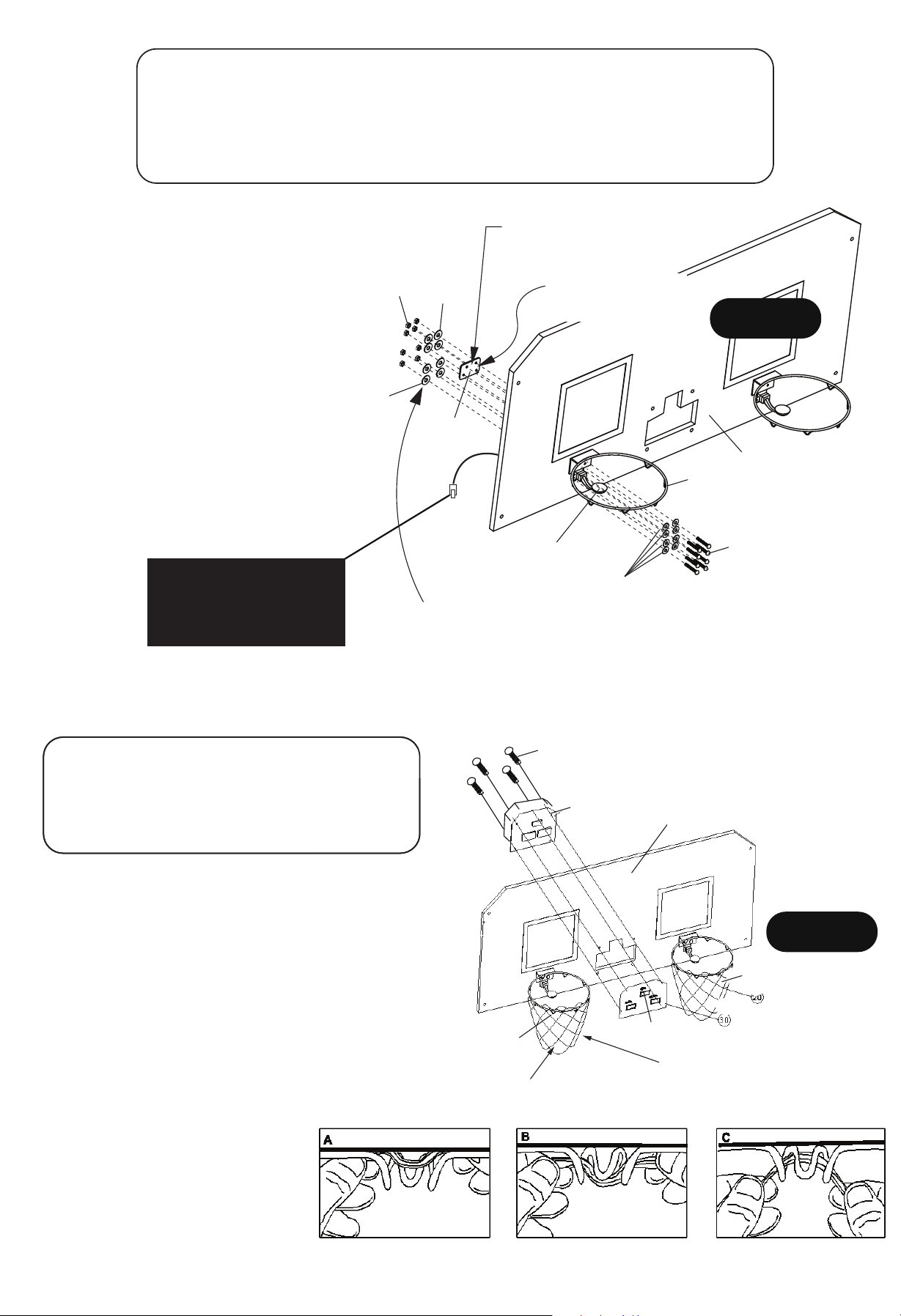
STEP 8
PARTS REQUIRED:
16 pcs - H1 M6 x 20 mm Allen Head Bolt 2 pcs - P18 Rim
24 pcs - H7 Flat Washer 2 pcs - P20 Rim Support Plate
8 pcs - H8 Plastic Flat Washer 2 pcs - P23 Mechanical Scoring Arm
16 pcs - H9 Lock Nut 1 pc - T1 Allen Wrench
1 pc - P17 Backboard 1 pc - T2 Wrench
Attach P18 Rims and P20 Rim Support
Plates to the P17 Backboard using
H1 Bolts, H7 Washers and H9 Lock
Nuts as shown in FIGURE 8.
Attach P23 Mechanical Scoring Arms
to
P17 Backboard using H1 Bolts,
H7 Washers, H8 Plastic Washers
and H9 Lock Nuts as shown
in FIGURE 8.
Use T1 Allen Wrench and
T2 Wrench to tighten H1 Bolts
& H9 Nuts.
NOTE:
P23 Mechanical Scoring Arm
sensor plug must pass through
P17 Backboard before attaching
the scoring arm.
NOTE: Use H8 Plastic
Flat Washers for P23
Scoring arm only.
NOTE: Use P20 Rim Support
Plate for P18 Rim only.
EVA Foam must
face Backboard
FIGURE 8
H9
H7
Plastic Flat
washers H8
P20
H1
P18
P23
P17
STEP 9
FIGURE 9
PARTS REQUIRED:
4 pcs - H11 3.5 x 8 mm Phillips Round Head Bolt
2 pcs - P19 Rim Net
1 pc - P21 Electronic Scorer Display
1 pc - P22 Electronic Scorer Face Plate
Attach P21 Electronic Scorer Display and
P22 Electronic Scorer Face Plate to P17
Backboard using
DO NOT Strip out H11 Screws.
H11 Bolts as shown
in FIGURE 9.
Loop the P19 Rim Net through the ram horns
on the P18 Rims as shown in FIGURE 9.
H11
P21
P22
P19
P19
H7
P17
Note:
This is a special rim & net
Net does have a
top and bottom,
The long loops go
to the top
designed to avoid entanglement
with the mechanical scoring arm.
13
For Customer Service Call 1-888-996-2729
© 2016 Escalade Sports
All RIghts Reserved.
STEP 10
PARTS REQUIRED:
2 pcs - H3 M6 x 45 mm Allen Head Bolt 4 pcs - H10 Plastic Bushing
4 pcs - H6 M6 x 75 mm Allen Head Bolt 1 pc - P15 Long Support Tube
12 pcs - H7 Flat Washer 1 pc - P24 Ramp Chute
6 pcs - H9 Lock Nut 1 pc - T1 Allen Wrench
1 pc - T2 Wrench
Slide elastic loop and sleeve of P24 Ramp Chute onto the P1 - Upper Tube as shown in FIGURE 10
and DETAIL I.
Slide P13/14 Tube assembly into the front sleeve of P24 Ramp Chute as shown in FIGURE 10 and DETAIL J.
Attach P9/P12 , P10/P12 and P11/P12 assembly tubes from STEP 3 to P14 - Front U-Tubes using
H6 Bolts, H7 Flat Washers, H10 Plastic Bushings and H9 Lock Nuts as shown in FIGURE 10 and DETAIL K.
Note: This is a pivot point. “Snug” tighten H9 Nuts only.
Make sure this assembly pivots freely.
Place P15 Long Support Tube over the front sleeve of P24 Ramp Chute and attach to P14 - Front U-Tubes
using H3 Bolts, H7 Flat Washers and H9 Lock Nuts as shown in FIGURE 10 and DETAIL L.
Use T1 Allen Wrench and T2 Wrench
to tighten H4 Bolts & H9 Nuts.
Elastic
Loop
Ramp Chute
Upper Sleeve
DETAIL I
DETAIL J
Ramp Chute
Front Sleeve
P1
P24
DETAIL K
P13/P14 Assembly
P12
P12
H6
H7
H10
H7
H9
P13
P14
H10
H7
H9
H3
H7
H9
P14
DETAIL L
P24
FIGURE 10
H6
H7
NOTE: P12 tube
inside of P14
NOTE: P12 tube
outside of P14
Outside
Ramp stays under the
P15 Long Support Tube
P15 Inside
Inside
14
For Customer Service Call 1-888-996-2729
© 2016 Escalade Sports
All RIghts Reserved.
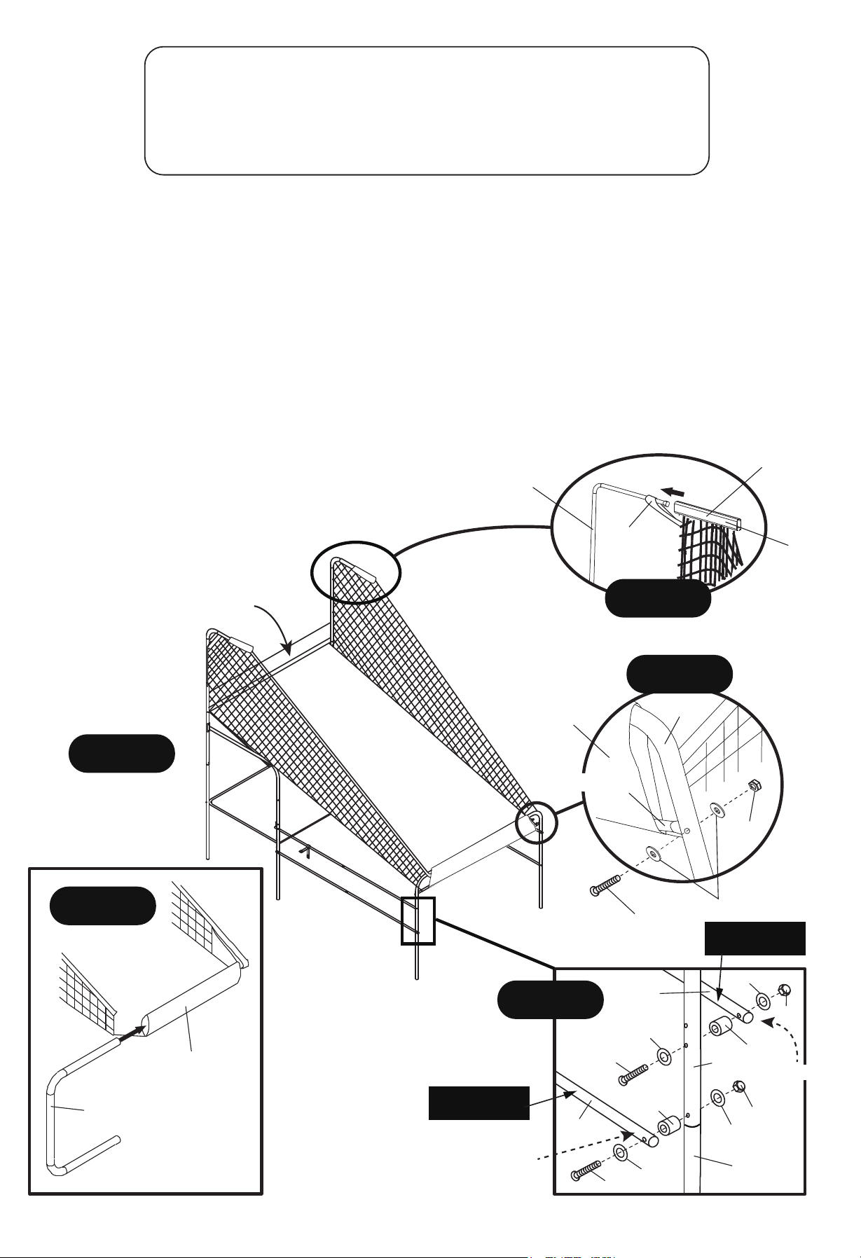
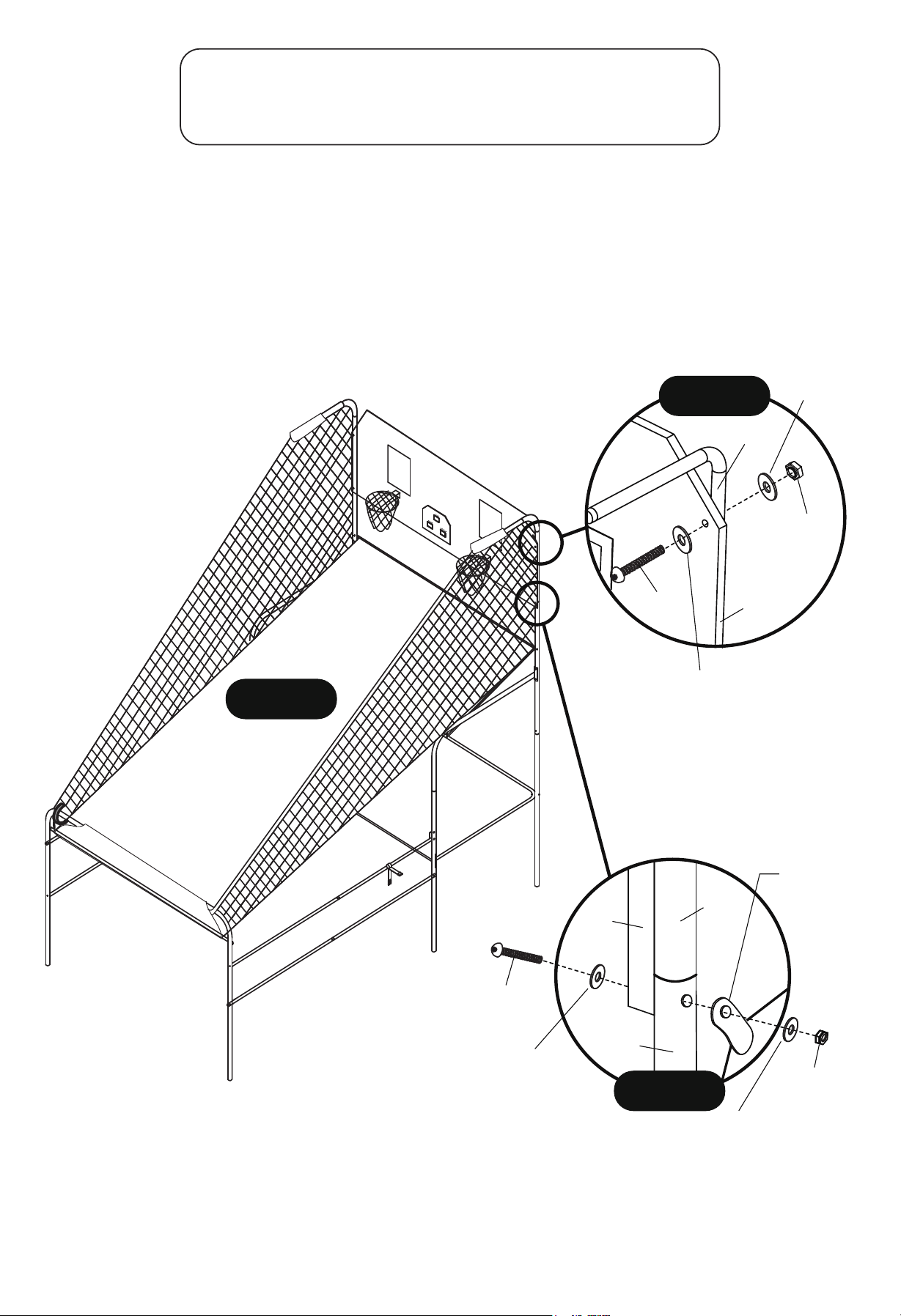
STEP 11
PARTS REQUIRED:
4 pcs - H5 M6 x 70 mm Allen Head Bolt 4 pcs - H9 Lock Nut
2 pcs - H7 Flat Washer 1 pc - T1 Allen Wrench
6 pcs - H8 Plastic Flat Washer 1 pc - T2 Wrench
With the help of another adult, Attach P17 Backboard to P1 - Upper Tube using H5 Bolts, H8 Plastic Washers,
H7 Flat Washers and H9 Lock Nuts as shown in FIGURE 11 and DETAIL M.
At each bottom hole of the backboard, attach ramp tabs of P24 Ramp Chute using H5 Bolts, H8 Plastic Washers,
and H9 Lock Nuts as shown in FIGURE 11 and DETAIL N.
Use T1 Allen Wrench and T2 Wrench to tighten H5 Bolts & H9 Nuts.
DETAIL M
DETAIL N
BACK VIEW
H5
H8 Plastic
Flat Washer
H7 Steel
Flat Washer
H9
P1
P17
P1
H5
H8 Plastic
Flat Washer
H8 Plastic
Flat Washer
Ramp Chute
Tab with
Eyelet
H9
P2
P17
FIGURE 11
15
For Customer Service Call 1-888-996-2729
© 2016 Escalade Sports
All RIghts Reserved.
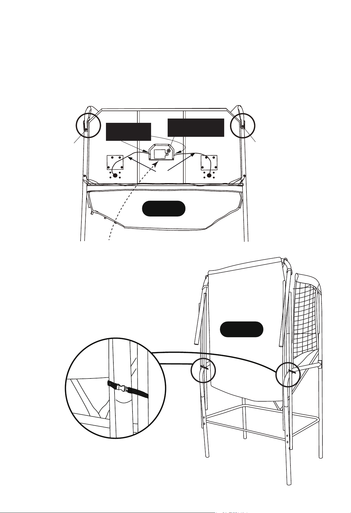
STEP 12
Connect P23 Mechanical Scoring Arm sensor wires to P21 Electronic Scorer as shown in FIGURE 12.
Secure Elastic Loops from P24 Ramp Chute to the back of P17 Backboard as shown in FIGURE 12.
Insert 3(three) pieces “AA” batteries at the backside of electronic scoreboard.
Plug the mechanical scoring arm plug into backside of the electronic scoreboard.
Press on/off button at the bottom backside of the electronic scoreboard to play and stop the game.
Turn off P21 Electronic Scorer when not in use.
Small phillips screwdriver
to remove and reinstall
battery cover
NOTE: Plug the mechanical
scoring arm plug into
backside of the electronic
scoreboard.
P23
Elastic LoopElastic Loop
On/off switch here on bottom.
FIGURE 12
FOLDING THE BASKETBALL DOUBLE SHOOTOUT
First remove P25 Locking Pin, then attach the Safety Straps
(Pre-installed) together to prevent the sides from falling.
Repeat procedure for the other side.
FIGURE 13
See” FIRST TIME BATTERY INSTALLATION AND NOTICE “ , before installing batteries, located on page 17

16
For Customer Service Call 1-888-996-2729
© 2016 Escalade S por t s
All Rights Reserved.
Insert 3(three) pieces “AA” batteries at the backside of electronic scoreboard.
Plug the mechanical scoring arm plug into backside of the electronic scoreboard.
Press on/off button at the bottom backside of the electronic scoreboard to play and stop the game.
USE OF YOUR SHOOTOUT
CARE AND USE OF YOUR SHOOTOUT
Congratulations! You have now assembled your Double Shootout.
Please note the Care and Use instructions below.
1. Product can be used OUTDOORS - but must be stored INDOORS.
2. DO NOT sit, climb or lean on the unit.
3.
4. DO NOT place backside of this product against wall as during play, the backside
of product could become damaged or your wall could become damaged.
DO NOT drag the unit when moving it, This will damage the legs.
PRODUCT PARTS LIST M01483
KEY PARTS DESCRIPTIONS QTY
H1
H2
H3
H4
H5
H6
H7
H8
H9
H10
H11
T1
T2
A1
A2
P1
P2
P3
P4
P5
P6
P7
P8
P9
P10
P11
P12
P13
P14
P15
P16
P17
P18
P19
P20
P21
P22
P23
P24
P25
C1
K1
M1
01483GRH1
01483GRH2
01483GRH3
01483GRH4
01483GRH5
01483GRH6
01483GRH7
01483GRH8
01483GRH9
01483GRH10
01483GRH11
01483GRT1
01483GRT2
01483GRA1
01483GRA2
01483GRP1
01483GRP2
01483GRP3
01483GRP4
01483GRP5
01483GRP6
01483GRP7
01483GRP8
01483GRP9
01483GRP10
01483GRP11
01483GRP12
01483GRP13
01483GRP14
01483GRP15
01483GRP16
01483GRP17
01483GRP18
01483GRP19
01483GRP20
01483GRP21
01483GRP22
01483GRP23
01483GRP24
01483GRP25
01483GRC1
01483GRK1
01483GRM1
M6 x 20 mm Allen Head Bolt
M6 x 35 mm Allen Head Bolt
M6 x 45 mm Allen Head Bolt
M6 x 50 mm Allen Head Bolt
M6 x 70 mm Allen Head Bolt
M6 x 75 mm Allen Head Bolt
M6 Flat Washer
M6 Plastic Flat Washer
M6 Lock Nut
Plastic Bushing
3.5 mm x 8 mm Phillips Round Head Bolt
Allen Wrench
Wrench
Air Pump with Needle
Basketball
Upper Tube
Middle Back Upright Tube
Left Lower Back Upright Tube
Right Lower Back Upright Tube
Left Back Bottom Support Tube
Right Back Bottom Support Tube
Front Support Tube
Front Upright Tube
Left Top Connect Tube
Right Top Connect Tube
Bottom Connect Tube
Connect Tube
Base Upright Tube
Front U-Tube
Long Support Tube
Short Support Tube
PC Backboard
Rim
Rim Net
Rim Support Plate
Electronic Scorer Display
Electronic Scorer Face Plate
Mechanical Scoring Arm
Ramp Chute
Locking Pin
Safety Strap (Pre-Installed)
Hardware Kit
Owner’s Manual
16
1
2
10
6
8
70
14
43
8
4
1
1
1
4
2
2
1
1
1
1
2
2
1
1
2
4
2
1
3
1
1
2
2
2
1
1
2
1
2
2
1
1

17
For Customer Service Call 1-888-996-2729
© 2016 Escalade S por t s
All Rights Reserved.
First Time Battery Installation:
Locate battery compartment for this product .
Use alkaline batteries for maximum performance .
Using a small Philips head screwdriver – loosen and remove the battery compartment cover
screw(s).
Remove battery compartment cover .
Install new batteries only after reading the “ Battery Information NOTICE“ !
Replace compartment cover and secure cover with the cover screw . Do not over tighten and
strip out the screw .
Notice:
1. Remove and replace batteries when the electrical features of this product work slowly or are not
functional .
2. Do not mix old and new batteries .
3. Do not mix different types of batteries : Alkaline , Standard ( Carbon-Zinc) , or rechargeable
( Nickel-Cadmium batteries ) .
4. Use Alkaline Batteries for maximum performance .
5. Do not use damaged batteries .
6. Use only batteries of the same or equivalent type as recommended.
7. Install new batteries as per matching the battery polarity guide ( + & - , positive and negative ) inside
of the battery compartment . Correct battery polarity installation is critical as to not damage the internal
electrical components as well as insuring the correct functionality of the product .
8. Do not short circuit the battery terminals .
9. Always remove exhausted , leaking, weak , and batteries from long periods of nonuse from the
product . Battery leakage and corrosion can cause damage .
10. Check the battery terminals are clean and bright before installing new batteries.
11. Dispose of old batteries safely and per local battery disposal codes .
12. Do not dispose of batteries into a fire as they may explode or leak.
13. If removable rechargeable batteries are used , they are to be charged under adult supervision .
14. Rechargeable batteries are to removed from the product before they are charged .
15. If you use a battery charger, it should be examined regularly for damage to the cord , plug, enclosure,
and other parts. Do not use a damaged or malfunctioning charger until it is properly repaired.
16. Non rechargeable batteries must not be recharged .
17. Always remove batteries from this product for extended storage and or non-use .
18. Should this product cause , or be affected by, local electrical interference , move it away from other
electrical equipment . Reset ( switching off and back on again and or removing and reinserting the
batteries ) if necessary .
IMPORTANT: BATTERY INFORMATION
Please retain this information for future reference. Batteries must be installed / replaced by an adult .

18
For Customer Service Call 1-888-996-2729
© 2016 Escalade S por t s
All Rights Reserved.
This consumer warranty extends to the original consumer purchase of any ESCALADESPORTS
Product (hereinafter referred as the "Product").
WARRANTY DURATION: This Product is warranted to the original consumer purchase of a pe-
riod of 90 days from the original purchase.
WARRANTY COVERAGE: ESCALADE SPORTS warrants to the original Consumer Purchaser
that any Product of its manufacture is free from defects in material and workmanship when used
for the intended purpose under normal use and conditions. THIS WARRANTY IS VOID IF THE
PRODUCT HAS BEEN DAMAGED BY ACCIDENT, UNREASONABLE USE, NEGLIGENCE,
IMPROPER SERVICE, FAILURE TO FOLLOW INSTRUCTIONS PROVIDED WITH THE PROD-
UCT OR OTHER CAUSES NOT ARISING OUT OF DEFECTS IN MATERIAL AND WORKMAN-
SHIP.
WARRANTY PERFORMANCE: During the above 90 day warranty period, ESCALADESPORTS
shall repair or replace with a comparable model, and Product, or component thereof, which may
prove defective under normal use and proper care, and which our examination shall disclose to
our satisfaction to be thus defective, please contact our Warranty Dept.
1-888-996-2729 / Warranty Dept.
Or Write us at:
Escalade® Sports, Inc. - P.O. Box 889, Evansville, IN 47706
Attn: Warranty Dept.
Or E-mail us at:
Other than shipping requirements no charge will be made for such repair or replacement of in-
warranty Products. ESCALADE SPORTS strongly recommends that the Product is insured for
value prior to mailing.
WARRANTY DISCLAIMERS: ANY IMPLIED WARRANTIES ARISING OUT OF
THIS SALE, INCLUDING BUT NOT LIMITED TO THE IMPLIED WARRANTIES OF
MERCHANTABILITY AND FITNESS FOR A PARTICULAR PURPOSE, ARE LIM-
ITED IN DURATION TO THE ABOVE 90 DAY PERIOD. ESCALADE SPORTS
SHALL NOT BE LIABLE FOR LOSS OF USE OF THE PRODUCT OR OTHER
CONSEQUENTIAL OR INCIDENTAL COSTS, EXPENSES OR DAMAGES IN-
CURRED BY THE CONSUMER OF ANY OTHER USE.
Some states do not allow the exclusion or limitation of implied warranties or consequential or
incidental damages, so the above limitations or exclusions may not apply to you.
LEGAL REMEDIES: This warranty gives you specific legal rights and you may also have other
rights which may vary from state to state.
90 DAY LIMITED WARRANTY