
1
IMPORTANT SAFETY INFORMATION
We thank you for choosing our product. To ensure your safety and health, please use this
equipment correctly. It is important to read this entire manual before assembling and using the
equipment. Safe and effective use can only be achieved if the equipment is assembled, maintained,
and used properly. It is your responsibility to ensure that all users of the equipment are informed of
all warnings and precautions.
1. Before starting any exercise program, you should consult your physician to determine if you
have any medical or physical conditions that could put your health and safety at risk or prevent
you from using the equipment properly. Your physician’s advice is essential if you are taking
medication that affects your heart rate, blood pressure, or cholesterol level.
2. Be aware of your body’s signals. Incorrect or excessive exercise can damage your health. Stop
exercising if you experience any of the following symptoms: pain, tightness in your chest,
irregular heartbeat, shortness of breath, lightheadedness, dizziness, or feelings of nausea. If
you do experience any of these conditions, you should consult your physician before continuing
with your exercise program.
3. Keep children and pets away from the equipment. The equipment is designed for adult use
only.
4. Use the equipment on a solid, flat level surface with a protective cover for your floor or carpet.
To ensure safety, the equipment should have at least 2 feet (60 CM) of free space all around it.
5. Ensure that all nuts and bolts are securely tightened before using the equipment. The safety of
the equipment can only be maintained if it is regularly examined for damage and/or wear and
tear.
6. Always use the equipment as indicated. If you find any defective components while assembling
or checking the equipment, or if you hear any unusual noises coming from the equipment
during exercise, discontinue use of the equipment immediately and do not use until the
problem has been rectified.
7. Wear suitable clothing while using the equipment. Avoid wearing loose clothing that may
become entangled in the equipment.
8. Do not place fingers or objects into the moving parts of the equipment.
9. The maximum weight capacity of this unit is 300 pounds(135KG).
10. This equipment is not suitable for therapeutic use.
11. To avoid bodily injury and/or damage to the product or property, proper lifting and moving are
required.
12. Your product is intended for use in cool and dry conditions. You should avoid storage in
extreme cold, hot or damp areas as this may lead to corrosion and other related problems.
13. This equipment is designed for indoor and home use only; it is not intended for commercial use.
2
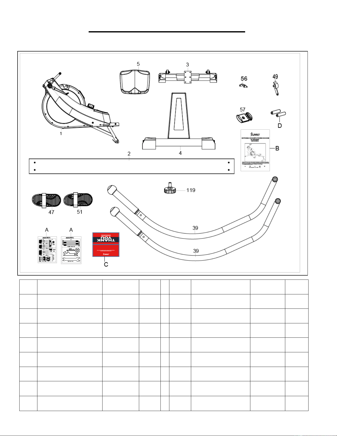
PRE-ASSEMBLY CHECK LIST
Before you start to assemble, please make sure all parts are included.
No.
Description
Spec.
Qty
No.
Description
Spec.
Qty
1
Main Frame
1
51
Right Pedal
1
2
Sliding Rail
1
49
Foot Limit Assembly
2
3
Front Stabilizer
1
39
Handlebar
2
4
Rear Stabilizer
1
123
Foot Pad
1
5
Seat
1
A
Hardware Package
2
56
Device Supporting
1
B
User Manual
1
57
Device Holder
1
C
Thank You Card
1
47
Left Pedal
2
D
Battery
2
3
HARDWARE PACKAGE 1
4
HARDWARE PACKAGE 2
Ordering Replacement Parts (U.S. and Canadian Customers only)
Please provide the following information in order for us to accurately identify the part(s) needed:
The model number (found on cover of manual)
The product name (found on cover of manual)
The part number found on the “EXPLODED DIAGRAM” and “PARTS LIST” (found near the end of
the manual)
5
ASSEMBLY INSTRUCTIONS
We value your experience using Sunny Health and Fitness products. For assistance with parts or
troubleshooting, please contact us at suppo[email protected] 1-877-90SUNNY (877-907-
8669).
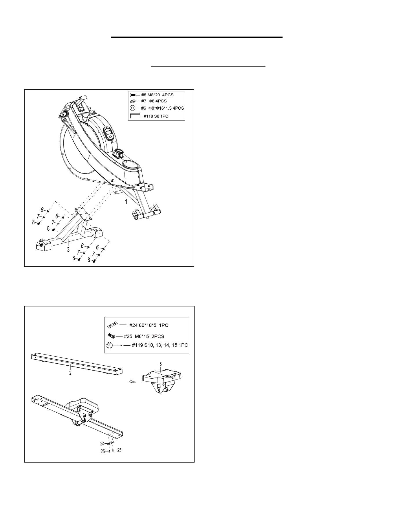
STEP 2:
Slide the Seat (No. 5) into the Sliding Rail (No. 2).
Attach 1 Limit Mat (No. 24) and 2 Screws (No. 25)
to the Sliding Rail (No. 2). Tighten and secure with
Spanner (No. 119).
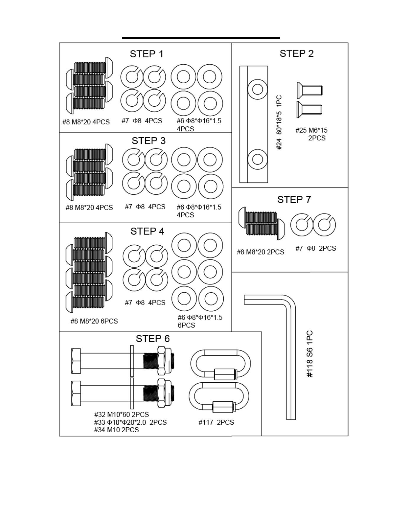
STEP 1:
Attach the Front Stabilizer (No. 3) to the Main
Frame (No. 1) using 4 Spring Washers (No. 7), 4
Washers (No. 6) and 4 Bolts (No. 8). Tighten and
secure with Allen Wrench (No. 118).
NOTICE: Two people should cooperate when
installing the machine, one people is holding the
machine for the other people to assemble, prevent
the machine from hitting people.
6
We value your experience using Sunny Health and Fitness products. For assistance with parts or
troubleshooting, please contact us at suppo[email protected] 1-877-90SUNNY (877-907-
8669).
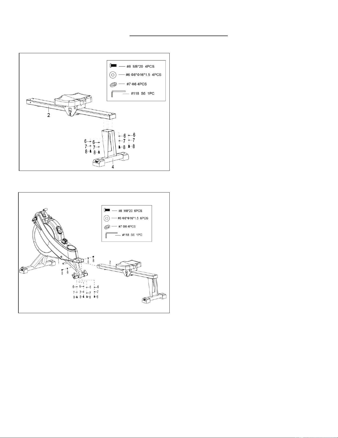
STEP 3:
Attach the Rear Stabilizer (No. 4) to the Sliding
Rail (No. 2) using 4 Bolts (No. 8), 4 Spring
Washers (No. 7) and 4 Washers (No. 6). Tighten
and secure with Allen Wrench (No. 118).
STEP 4:
Attach the Sliding Rail (No. 2) to the Main
Frame (No. 1) by securing 2 Bolts (No. 8), 2
Washers (No. 6) onto the left and right sides of
the Main Frame (No. 1). Don’t tighten the Bolts
(No. 8) now.
Secure 4 Bolts (No. 8), 4 Washers (No. 6) and
4 Spring Washers (No. 7) to the bottom of the
Main Frame (No. 1). Tighten all the 6 Bolts
(No. 8) with Allen Wrench (No.118) now.
7
We value your experience using Sunny Health and Fitness products. For assistance with parts or
troubleshooting, please contact us at suppo[email protected] 1-877-90SUNNY (877-907-
8669).
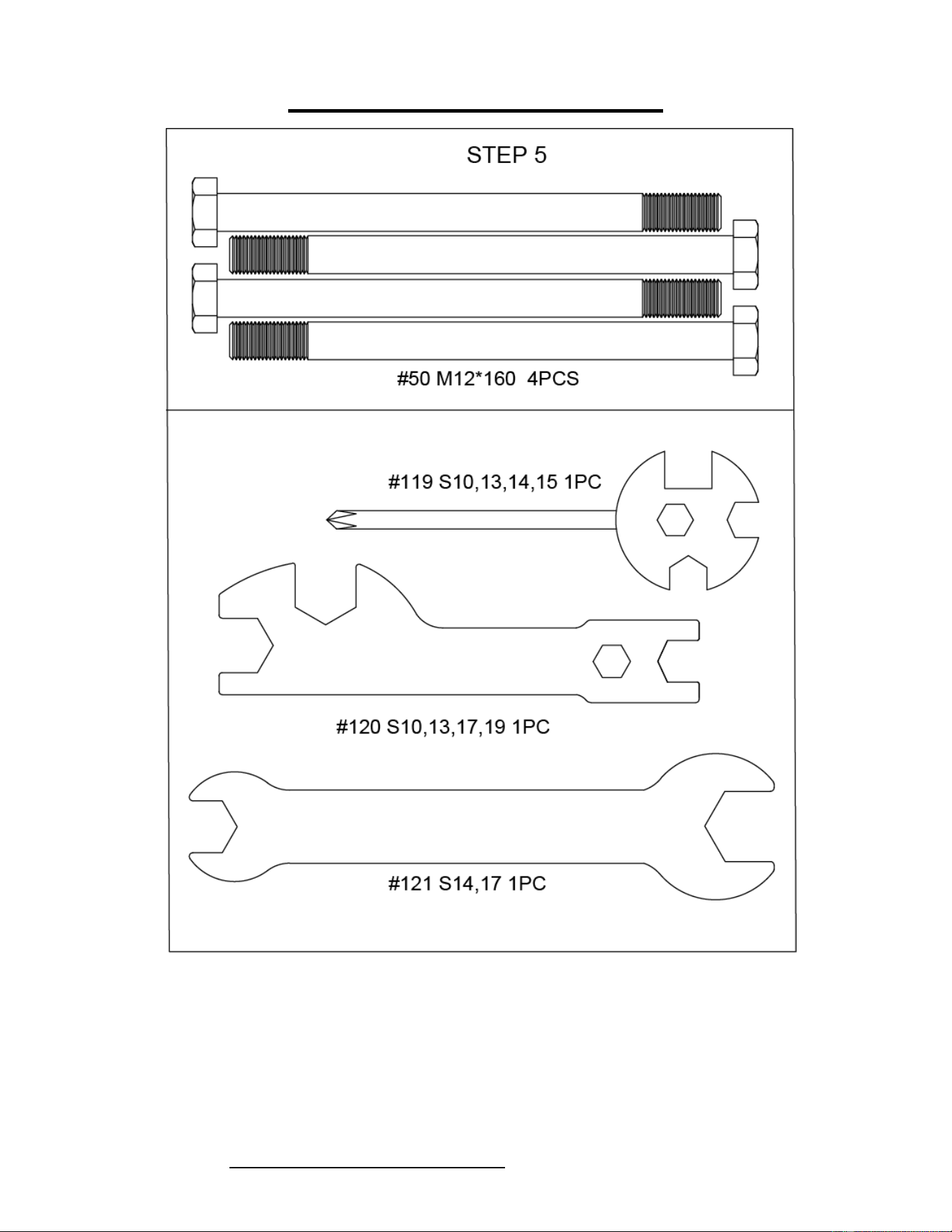
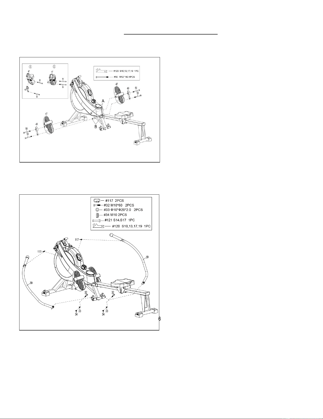
STEP 5:
Insert 2 Bolts (No. 50) through the Left Pedals
(No. 47), Right Pedals (No. 51) and 2 Foot Limit
Assembly (No. 49) into the upper hole at position
A of the Main Frame (No. 1). Tighten with
Spanner (No. 120).
Insert 2 Bolts (No. 50) through Foot Limit
Assembly (No. 49) into the bottom hole at position
B of the Main Frame (No. 1). Tighten with
Spanner (No. 120).
NOTE: The Left Pedals (No. 47) and Right
Pedals (No. 51) should rest on the bottom Bolts
(No. 50) at position B.
STEP 6:
Attach the 2 Handlebar (No. 39) to the U Bracket
(No. 31) using 2 Nuts (No. 34) and 2 Washers (No.
33) and 2 Bolts (No. 32). Tighten and secure with
Spanner (No. 120) and Spanner (No. 121).
Attach 2 Gourd Hooks (No. 117) into two hooks in
the each Handlebar (No. 39), Attach another side to
the 2 Digging Ropes (No. 116) in the Main Frame
(No. 1).
8
We value your experience using Sunny Health and Fitness products. For assistance with parts or
troubleshooting, please contact us at suppo[email protected] 1-877-90SUNNY (877-907-
8669).
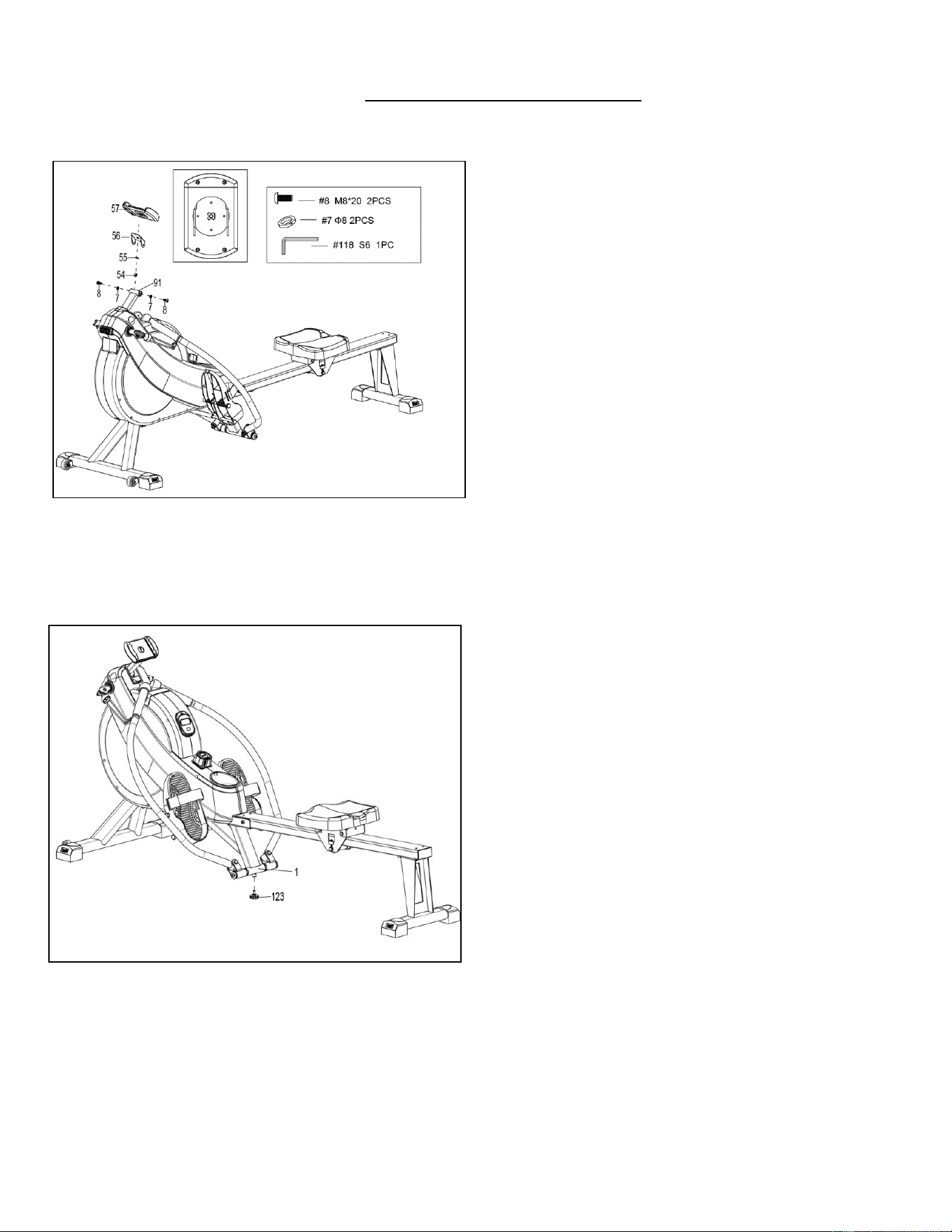
STEP 7:
Remove 1 Washer (No. 55), 1 Nut (No. 54) from
Device Holder (No. 57) by hand.
Attach the Device Holder (No. 57) to the Device
Supporting (No. 56) using 1 Washer (No. 55), 1
Nut (No. 54) which were remove. Tighten and
secure by hand.
NOTE: When assemble the Device Holder (No.
57), ensure that it’s aligned to the Device
Supporting (No. 56).
Attach the Device Supporting (No. 56) to
Computer Supporting Tube (No. 91) using 2
Bolts (No. 8) and 2 Spring Washers (No. 7).
Tighten and secure with Allen Wrench (No.
118).
STEP 8:
Attach the Foot Pad (No. 123) to the Main
Frame (No. 1). Tighten and secure by hand.
The assembly is complete!
9
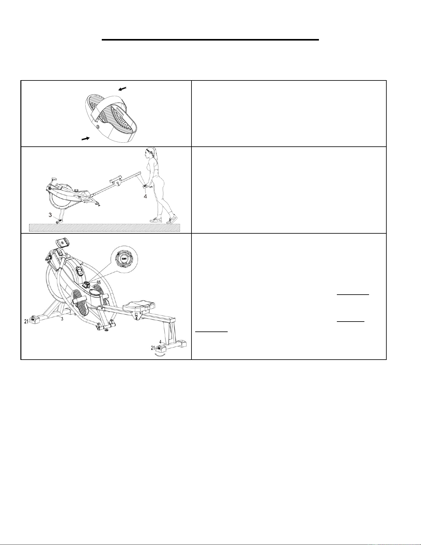
ADJUSTMENTS & USAGE GUIDE
CAUTION! Moving parts, such as the seat, can cut and crush. Keep hands clear of the sliding rail
during use!
PEDAL STRAP ADJUSTMENT
The pedal straps are adjustable and can be
personalized to fit the user’s foot size.
NOTE: To avoid injury, please adjust the pedal
straps to user’s foot before exercise.
MOVING THE ROWER
To move the rower, lift up the Rear Stabilizer (No.
4) until the transportation wheels on the Front
Stabilizer (No. 3) touch the ground. With the
transportation wheels on the ground, you can
transport the rower to the desired location with
ease.
ADJUSTING THE BALANCE AND RESISTANCE
Adjust the Left & Right End Cap (No. 20 & No. 21) on
the Rear Stabilizer (No. 4) and Front Stabilizer (No.
3) if the rower is unbalanced during use.
Turn the Tension Control Knob (No. 65) clockwise
to increase the level of resistance.
Turn the Tension Control Knob (No. 65) counter-
clockwise to decrease the level of resistance.
Tension levels are set at Level 1 being the lowest and
Level 16 being the highest.
10
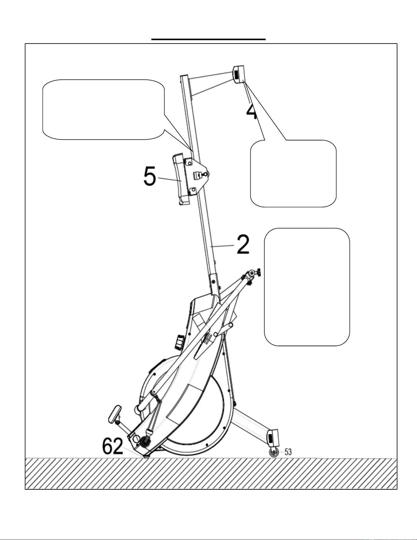
STORAGE GUIDE
CAUTION!
Use caution when you
vertically placing the
Sliding Rail (No. 2) as
your head may touch the
Rear Stabilizer (No. 4).
When not in use, you
can save space by
placing the rower upright
on the floor with Rubber
Mat (No. 62).
SAFETY NOTE: The
Seat (No. 5) will glide
down when placing the
Sliding Rail (No. 2) in
an upright position.
CAUTION!
The Seat (No. 5) will glide down
when placing the Sliding Rail (No. 2)
in an upright position.
11
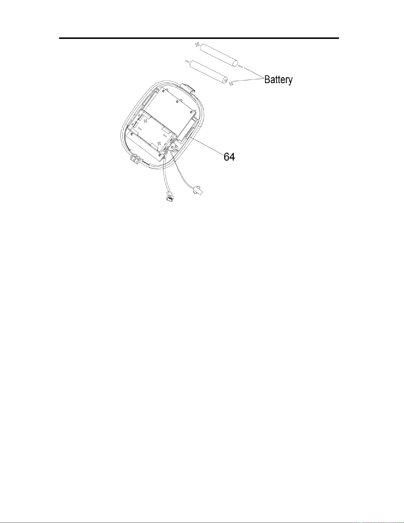
BATTERY INSTALLATION & REPLACEMENT
BATTERY INSTALLATION:
1. Press the buckle on the bottom of Computer (No. 64), then remove Computer (No. 64) from Main Frame
(No. 1).
2. Take out 2 AAA batteries from manual bag.
3. Install the 2pcs AAA batteries into the battery case on the back of the Computer (No. 64), Pay attention to
the battery + and – poles before installing. Press the buckle on the bottom of Computer (No. 64) and put
the Computer (No. 64) back onto the Main Frame (No. 1).
The installation is complete!
BATTERY REPLACEMENT:
1. Press the buckle on the bottom of Computer (No. 64), then remove Computer (No. 64) from Main Frame
(No. 1)
2. Take out the 2pcs old AAA batteries from the battery case and install 2pcs new AAA batteries into the
battery case on the back of the Computer (No. 64). Pay attention to the battery + and – poles before
installing. Press the buckle on the bottom of Computer (No. 64) and put the Computer (No. 64) back onto
the Main Frame (No. 1).
The replacement is complete!
NOTE: Always change both batteries at the same time. Do not mix battery types and do not mix old and new
batteries. Dispose batteries according to your state and regional guidelines.
12
EXERCISE COMPUTER
WIRELESS HEART RATE :
1. The wireless heart rate icon will flash when the meter is on. If the heart rate monitor is not
connected within 1 minute, the wireless heart rate icon will turn off.
2. After exercise resumes, the wireless heart rate icon will flash. If the heart rate monitor is not
connected within 1 minute, the wireless heart rate icon will turn off.
3. When the meter wakes from sleep mode, the wireless heart rate icon will flash. If the heart rate
monitor is not connected within 1 minute, the wireless heart rate icon will turn off.
4. The wireless heart rate icon will flash when the MODE key is pressed during exercise. If the heart
rate monitor is not connected within 1 minute, the wireless heart rate icon will turn off.
5. The wireless heart rate icon will stay on when the heart rate monitor is connected.
NOTE: The heart rate monitor is not included. Wireless heart rate function works with SunnyFit Heart
Rate Monitor HR200.
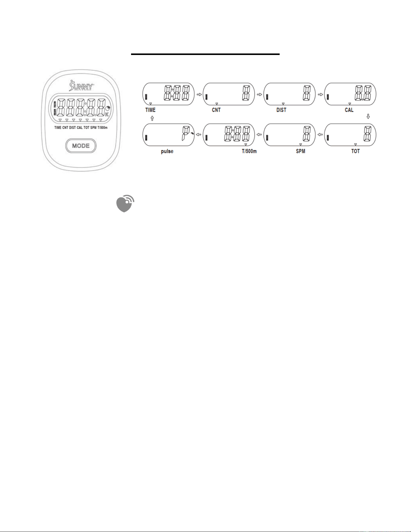
FUNCTION BUTTON
MODE:
Press the button to switch display or automatically display through each function value in
sequence every 6 seconds.
Hold the MODE key for 2 seconds to reset all values except TOT when the Bluetooth is not
connected.

13
Press and hold the MODE key for 6 seconds to disconnect from both the SunnyFit APP and the
heart rate monitor; then, the meter will enter sleep mode.
OPERATION:
1 Power on:
Installs 2 pieces of 1.5V AAA batteries. (Whenever batteries are removed, all the functions
values will be reset to zero.)
2. Sleep mode/wake up
After entering speed signal, each function will skip to display. STOP will be displayed once no speed
signal detected for 10 seconds.
The meter will shut off automatically and disconnect the heart rate monitor if there is no activity for 4
minutes.
Sleep mode:
A. No connection with Bluetooth module.
B. No speed signal and button operation input
It will enter the sleep mode then the screen and broadcast will turn off and the pulse measurement
will stop if A and B exist simultaneously.
3. SCAN: After power on or press the mode button, automatically scan through each function value in
sequence every 6 seconds. SCAN-->TIME-->CNT-->DIST-->CAL-->TOT-->SPM-->T/500M--
>PULSE-->SCAN
4. TIME: Accumulates total training time from 00:00 up to 999:59.
5. CNT: Display current training frequency from 0 up to 9999.
6. DIST: Accumulates training distance from 0 up to 99999 Meter.
7. CAL: Accumulates calories consumption during training from 0.0 up to 9999.9 kcal
Note: This data is a rough guide for comparison of different exercise sessions which can
not be used in medical treatment.
8. TOT: Accumulates training frequency from 0 up to 99999K.
9. SPM: Displays current stroke per minimute.
10. T/500M: Displays Time for trainging of 500 Meter
11. PULSE (Needs to pair with the Bluetooth device)
Display the user's heart rate from 30-240 upon pulse signal detected with pulse symbol
glittering.The pulse graphic will not glitter upon no pulse signal detected.

14
The monitor can connect with the Bluetooth pulse device under below conditions. The Bluetooth
symbol will glitter under the successful connection.
1. One minutes after power on.
2. Restart the training within 1 minute after STOP graphic appear.
3. Wake up from the sleep mode within 1 minute.
4. Press the mode button within 1 minute during the training.
The following scenarios can disconnect the electronic watch from the Bluetooth heart rate armband:
1. Press and hold the Mode button for more than 6 seconds
2. Stop exercising for more than 4 minutes
Note:
1. If the computer displays abnormally, please re-install the battery and try again.
2. Battery Spec: 1.5V, AAA (2PCS).
3. The batteries must be removed from the appliance before it is scrapped and that they are disposed
of safely.

15
APP CONNECTION:
Connect Smart Equipment to SunnyFit App:
1. Scan to download SunnyFit from the app store:
2. Ensure that the Bluetooth function is turned on from your mobile device.
3. If this is your first time using the SunnyFit app, follow the in-app instructions to register for your
free SunnyFit account and log in.
4. Begin any workout activity that matches your smart equipment, then follow the onscreen
prompts to search for and connect to your smart equipment.
5. When connected, your stats and records will be displayed at the end of your course/session,
and recorded in your account profile!
Troubleshooting:
If you are having trouble connecting your smart equipment, visit www.sunnyfit.com/guide or
scan the QR code below:
If you require additional support, please contact [email protected].
16
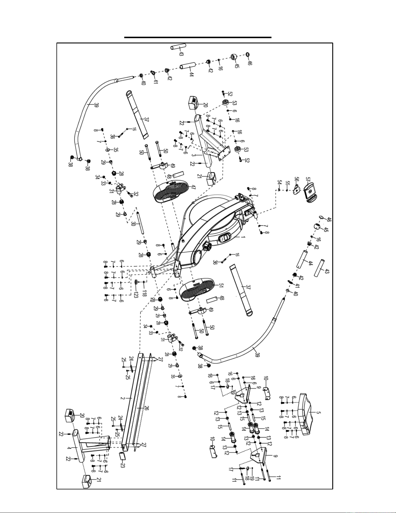
EXPLODED DIAGRAM 1
17
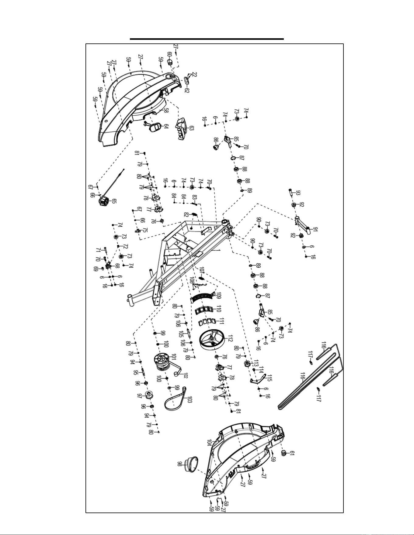
EXPLODED DIAGRAM 2

18
PARTS LIST
No.
Description
Spec.
Qty
No.
Description
Spec.
Qty
1
Main Frame
1
34
Nut
M10
2
2
Sliding Rail
1
35
Big Washer
Ф8*Ф32*2.0
2
3
Front Stabilizer
1
36
Bolt
M8*60
2
4
Rear Stabilizer
1
37
Pedal Strap
2
5
Seat
1
38
Plastic Axle Sleeve
Ф28*14
4
6
Washer
Ф8*Ф16*1.5
30
39
Handlebar
2
7
Spring Washer
Ф8
20
40
Handrail Sleeve
2
8
Bolt
M8*20
22
41
Bracket
2
9
Seat Supporting Board
2
42
Handle Tube Shaft Sleeve
4
10
U Shape Bracket
2
43
Handrail Sleeve
Ф28*2.0
2
11
Bolt
M8*125
3
44
Foam Grip
Ф27*Ф33*158
2
12
Spacer
Ф15*Ф8*4
6
45
Round End Cap
Ф50*34.2
2
13
Bearing
608
6
46
Round Cap
Ф37.5*12.8
2
14
Wheel
3
47
Left Pedal
1
15
Casing Pipe for Idler Wheel
3
48
Silicone Pad
2
16
Nut
M8
16
49
Foot Limit Assembly
2
17
Adjusting Screw
M6*36
2
50
Bolt
M12*160
4
18
U Shape Baffle
2
51
Right Pedal
1
19
Nut
M6
2
52
Bolt
M8*40
2
20
Left End Cap
2
53
Roller
Φ50*22.5*Φ8.2
2
21
Right End Cap
2
54
Nut
M6
1
22
Screw
ST4.2*20
6
55
Washer
Ф6*Ф16*1.2
1
23
Square Plug
1
56
Device Supporting
1
24
Limit Mat
80*18*5
2
57
Device Holder
1
25
Screw
M6*15
4
58
Left Cover
1
26
U Shape Stainless Steel Sheet
1
59
Screw
ST4.2*25
10
27
Screw
ST4.2*15
11
60
Left Turn Axle Cover
1
28
Plastic Axle Sleeve
Ф32*2
6
61
Right Turn Axle Cover
1
29
Inner Shaft Sleeve
Ф23.5*20
6
62
Rubber Mat
1
30
Long Shaft
Φ16*249
1
63
Handle Guide
1
31
U Bracket
2
64
Computer
1
32
Bolt
M10*60
2
65
Tension Control Knob
L=1200MM
1
33
Washer
Ф10*Ф20*2.0
2
66
Big Washer
Ф18*Ф5*1.5
2

19
No.
Description
Spec.
Qty
No.
Description
Spec.
Qty
67
Bolt
M5*12
2
96
Bearing
6000
2
68
Pulley Assembly
1
97
Mesh Belt Pulley
1
69
Pulley Long Spacer Sleeve II
Ф12*Ф8.2*13
1
98
Bottle holder
1
70
Bolt
M8*35
6
99
Nut
M10*1.0*9
2
71
Bolt
M8*50
1
100
Nut
M10*1
2
72
Pulley Long Spacer Sleeve I
Ф12*Ф8.2*13
1
101
Volute Spring Complete Sets
1
73
Pulley Assembly
Ф34*12
7
102
Mesh Belt
1
74
Pulley Short Spacer Sleeve
Ф12*Ф8.2*5
8
103
Belt
PJ320
1
75
Sensor Wire
L=400MM
1
104
Right Cover
1
76
Bearing
6001
2
105
Magnetic Plate
Ф12*75.2*M6
1
77
Bearing Seat
2
106
Shaft Snap Ring
Ф12*1.0
2
78
Bearing End Cover
2
107
Spring
1
79
Washer
Ф6*Ф12*1.0
13
108
Screw
ST2.9*9
5
80
Bolt
M6*12
11
109
Magnetic Bracket
1
81
Bolt
M6*12
2
110
Magnet Seat
1
82
Spring
Ф15*50*Ф1.5
1
111
Magnet
40*25*10
4
83
Bolt
M6*45
1
112
Flywheel
Ф200
1
84
Nut
M6
2
113
Idler Wheel
1
85
Pulley Assembly
2
114
Bolt
M8*20
1
86
Pull String Tee Combination
Ф37*34
2
115
Idler Wheel Shaft
1
87
Clasp Ring
Ф35*1.0
2
116
Digging Rope
Ф5
3
88
Bearing
6003
4
117
Gourd Hook
2
89
Shaft Snap Ring
Φ17*1
2
118
Allen Wrench
S6
1
90
Pulley Long Spacer Sleeve III
Ф12*Ф8.2*10
2
119
Spanner
S10,13,14,15
1
91
Computer Supporting Tube
1
120
Spanner
S10,13,17,19
1
92
Axle Sleeve
2
121
Spanner
S14,17
1
93
Bolt
Φ14*77*M8
1
122
Nut
M8
1
94
Shaft Snap Ring
Ф10*1.0
2
123
Foot Pad
M8*30
1
95
Belt Pulley Shaft
Ф10*79.5
1
Version 1.0

20