
Installation Guide
Quality, Design and Innovation
home.liebherr.com/fridge-manuals
Contents
1 General safety instructions.................................. 2
2 Installation dimensions........................................ 3
3 Transporting appliance......................................... 4
4 Unpacking the appliance...................................... 4
5 Disposing of packaging......................................... 4
6 Side by side assembly........................................... 4
The manufacturer is continually working on the further
development of all types and models. Please be aware that
we reserve the right to make changes to the shape, equip‐
ment and technology.
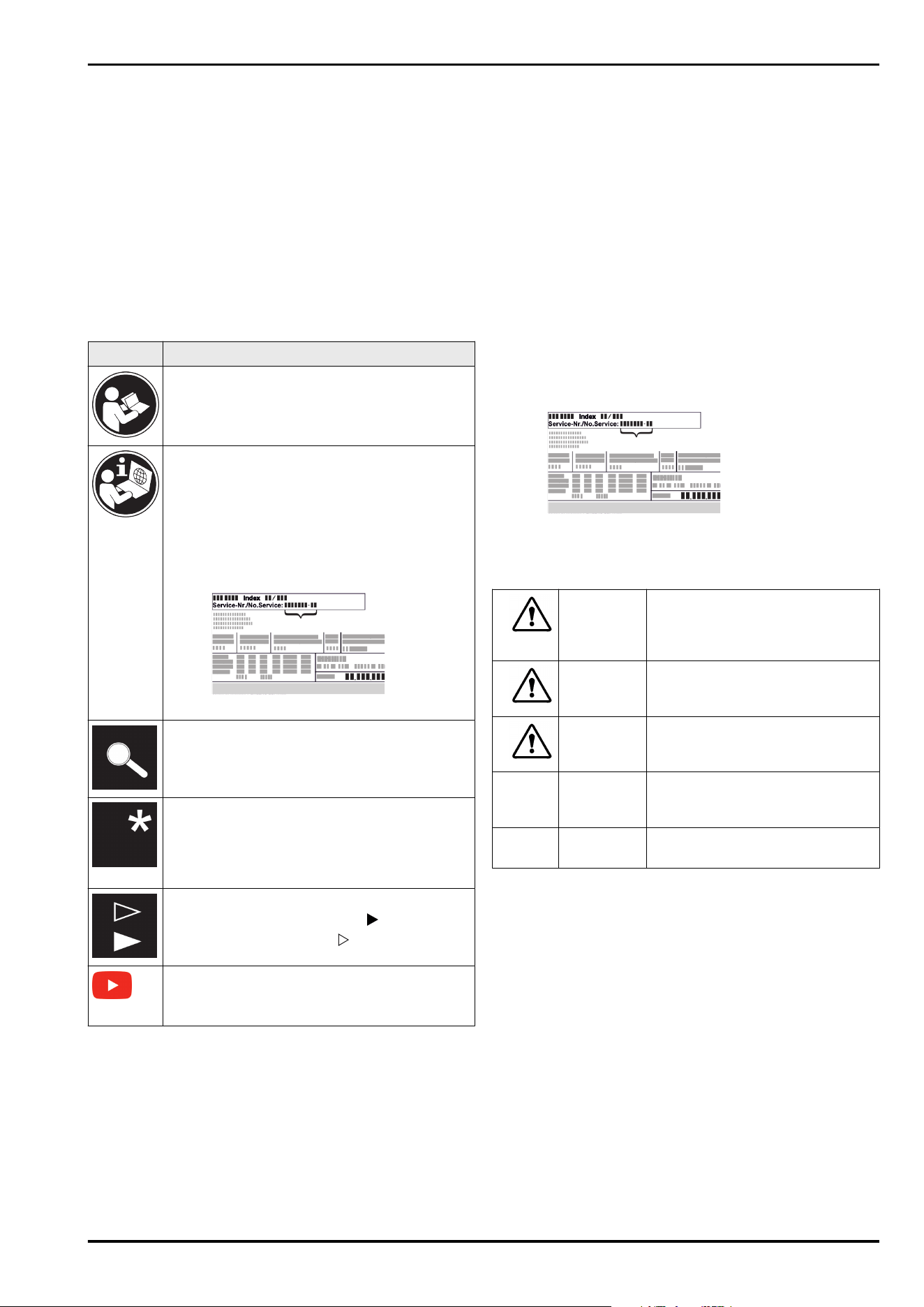
Symbol
Explanation
Read instructions
Please read the information in these instruc‐
tions carefully to understand all of the benefits
of your new appliance.
Full instructions on the internet
You can find detailed instructions on the
internet using the QR code on the front
of these instruction or by entering the
service number at home.liebherr.com/fridge-
manuals.
The service number can be found on the serial
tag:
Fig.Example illustration
Check appliance
Check all parts for transport damage. If you
have any complaints, please contact your
agent or customer service.
Differences
These instructions apply to a range of models,
so differences are possible. Sections that
apply to certain models only are marked with
an asterisk (*).
Instructions and results
Instructions are marked with a .
Results are marked with a .
Videos
Videos about the appliances are available on
the YouTube channels of Liebherr-Hausgeräte.
1 General safety instructions
-
Please keep this assembly manual in a safe
place so you can refer back to it at any
time.
-
If you pass the appliance on, please hand
this assembly manual to the next user.
-
Read this assembly manual carefully before
installation and use to ensure safe and
correct use of the appliance. Follow
the instructions, safety instructions and
warning messages included at all times.
They are important for ensuring you can
operate and install the appliance safely and
without any problems.
-
First read the general safety instructions in
the “General safety instructions” section of
the operating instructions, which accom‐
pany these installation instructions, and
follow them. If you cannot find the
operating instructions, you can down‐
load the operating instructions from the
internet by entering the service number
at home.liebherr.com/fridge-manuals. The
service number can be found on the serial
tag:
-
Observe the warning messages and other
detailed information in the other sections
when installing the appliance:
DANGER
identifies a situation involving
direct danger which, if not obvi‐
ated, may result in death or severe
bodily injury.
WARNING identifies a dangerous situation
which, if not obviated, may result
in death or severe bodily injury.
CAUTION identifies a dangerous situation
which, if not obviated, may result
in minor or medium bodily injury.
NOTICE identifies a dangerous situation
which, if not obviated, may result
in damage to property.
Note identifies useful instructions and
tips.
General safety instructions
2 * Depending on model and options
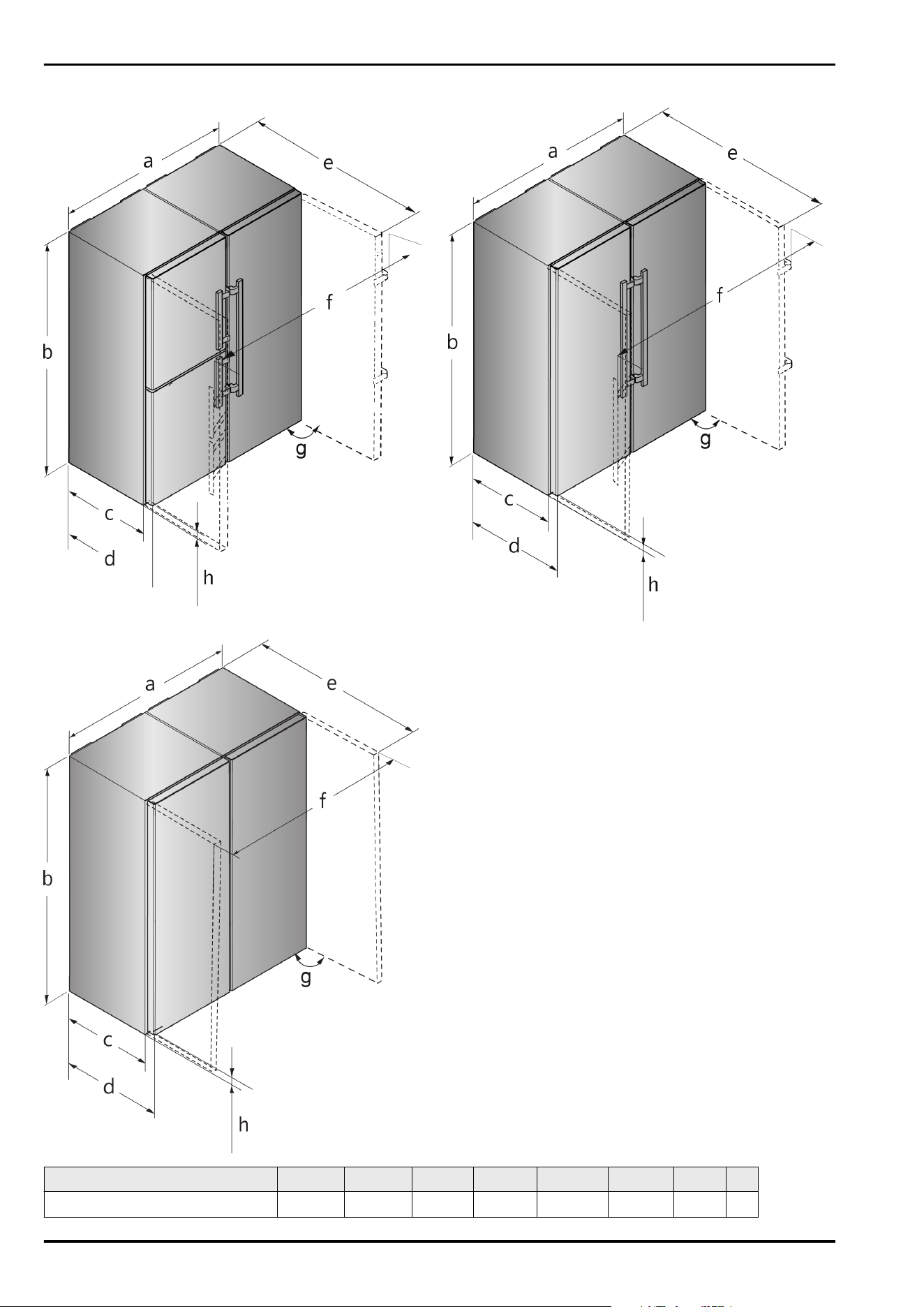
2 Installation dimensions
Fig. 1 Example illustration
Fig. 2 Example illustration
Fig. 3 Example illustration
For appliances with a lever handle
a
b c d e f h g
S(BN)(CN)(FN)(sd)(st)(bd)(bs) 52..(i) 1204mm 1855mm
611mm
x
675mm
x
1222mm
x
1318mm 35mm 90°
Installation dimensions
* Depending on model and options 3
a b c d e f h g
CBN.. 76.. 1504mm 1855mm
611mm
x
675mm
x
1365mm
x
1618mm 35mm 90°
For appliances with a lever handle
x
The use of wall spacers increases the dimensions by
15mm .
The dimensions with an open door apply for an opening
angle of 90°. The clearances vary depending on the opening
angle.
For appliances with recessed grip
a b c d e f h g
SFN(sd)(sf)(bd) 52.. 1226mm 1855mm
611mm
x
675mm
x
1217mm
x
1252mm 35mm 90°
For appliances with a recessed grip
x
The use of wall spacers increases the dimensions by
15mm .
The dimensions with an open door apply for an opening
angle of 90°. The clearances vary depending on the opening
angle.
3 Transporting appliance
WARNING
Risk of injury due to broken glass!*
When transporting at an altitude of more than 1500 m, the
glass panes of the door may break. This can result in sharp-
edged fragments, which can cause serious injuries.
u
Take appropriate protective action.
Note when transporting the appliance:
u
Transport the appliance upright.
u
Use two people to transport the appliance.
During first use:
u
Transport the appliance packaged.
When transporting appliances after initial commissioning
(e. g. moving or cleaning):
u
Empty the appliance.
u
Secure the door against unintentional opening.
4 Unpacking the appliance
Before you connect the appliance, report any damage imme‐
diately to the delivery company.
u
Check the appliance and the packaging for damage
during transport. Contact the supplier immediately if you
suspect any level of damage.
u
Remove all materials from the back or the side walls
of the appliance that may prevent proper installation or
ventilation.
u
Remove all protective films from the appliance. Do not
use sharp or pointed objects for this.
u
Take the power cable from the rear of the appliance.
Remove the cable brackets when you do this, otherwise
there will be noise caused by vibrations!
5 Disposing of packaging
WARNING
Danger of suffocation due to packing material and plastic
film!
u
Do not allow children to play with packing material.
The packaging is made of recyclable materials:
-
corrugated board/cardboard
-
expanded polystyrene parts
-
polythene bags and sheets
-
polypropylene straps
-
nailed wooden frame with polyethylene panel*
u
Take the packaging material to an official collecting
point.
6 Side by side assembly
Set up the freezer or the appliance with the freezer
compartment from the left when viewed from the front.
These appliances are equipped with a side-wall heater on
the right hand side to prevent condensation forming.
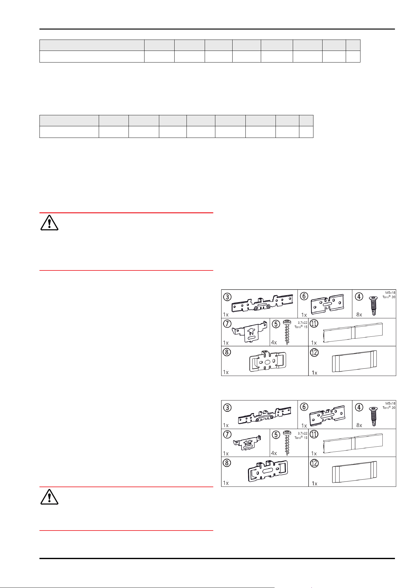
All the assembly components are supplied with the appli‐
ance.
Assembly parts in the accessory kit
For appliances with lever handle
Fig.4
For appliances with recessed grip
Fig.5
For all appliances
Transporting appliance
4 * Depending on model and options
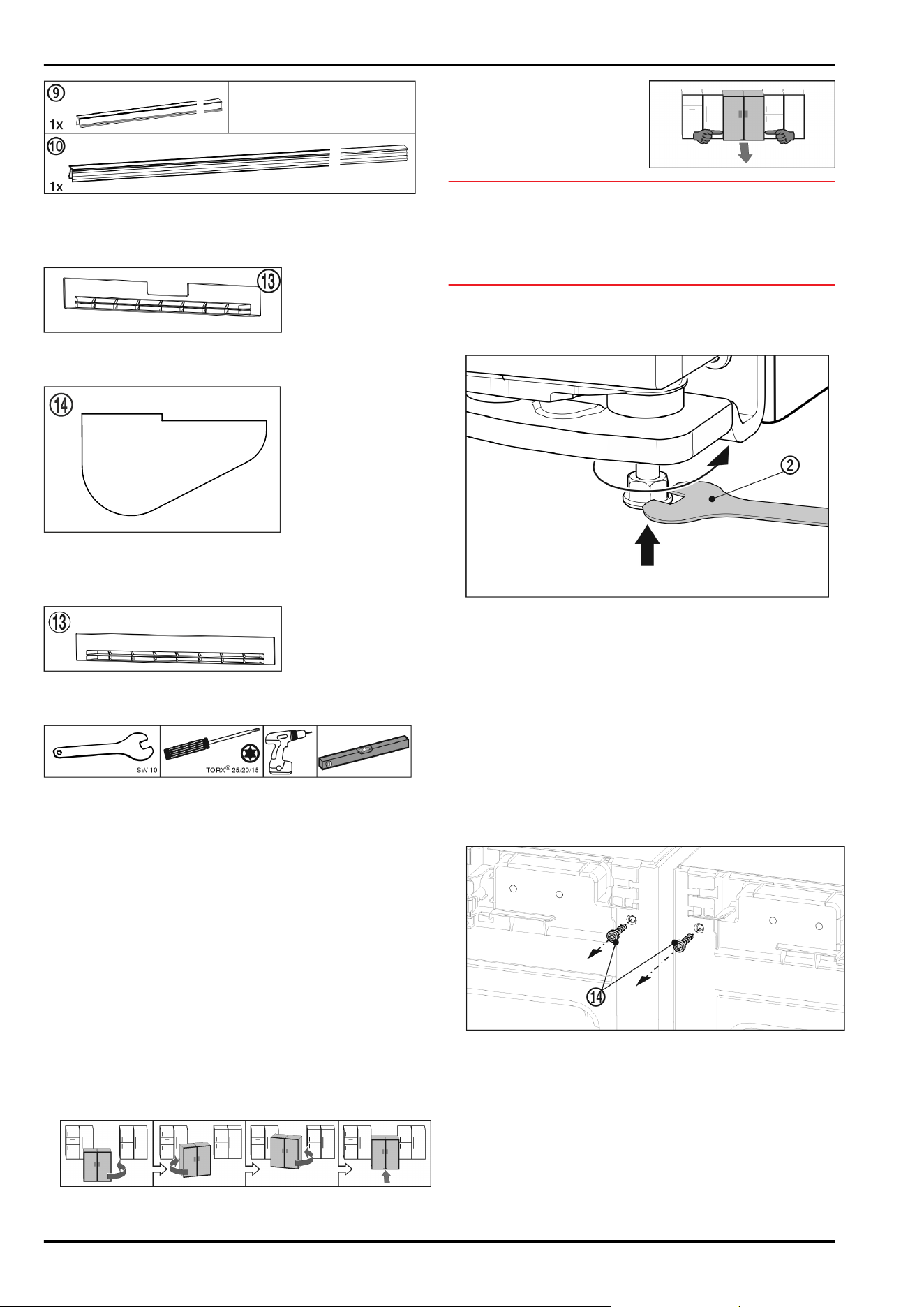
Fig.6
For appliances with bottom soft stop mechanism
Base trims
Fig.7
Swap bearing block cover
Fig.8
For appliances without bottom soft stop mechanism
Base trims
Fig.9
Tool for assembly
Fig. 10
Ensure that the following tools are to hand:
q
Size 10 open-ended spanner (supplied)
q
Torx® 25/20/15 screwdriver
q
Cordless screwdriver
q
Spirit level
Information on moving the SBS combination:
q
Set up the appliances as close to the final position as
possible before assembly.
The appliances must be accessible on all sides for
correct assembly.
q
When moving the appliances after assembly, always take
hold from the front outer corners. Never press your knee
against the side walls or door.
q
The SBS combination can be moved most easily when
moved diagonally, that is by alternately pushing from the
left and right corners.
If the combination is standing directly in front of the
recess, push it in straight.
q
If the combination has to
be pulled out of the recess
again, take hold of the
bottom third of the combi‐
nation and pull forward
straight.
NOTICE
Risk of damage when moving the combined SBS appliance!
The combined SBS appliance is heavy once assembled. The
appliance may be dented by improper movement.
u
Observe the information given on moving the appliance
(see above).
u
Take off all protective film from the exterior of the appli‐
ance.
Bottom front of the appliance:
Fig.11
u
Tighten the outer adjusting feet. The appliances can be
moved easier.
For appliances with lever handle
u
Push both appliances so that they are approx. 10 mm
apart from each other, and they are positioned flush
facing forwards.
For appliances with recessed grip
u
Push both appliances so that they are approx. 32 mm
apart from each other, and they are positioned flush
facing forwards.
u
Straighten the appliances up using a spirit level on the
top of the appliance.
Top front of the appliance:
Fig.12
u
Remove the existing covers.
u
Before fitting the top bracket remove both earthing
screws Fig.12(14).
u
Store the earthing screws safely. The screws will be
necessary for fitting the bracket as shown below.
Side by side assembly
* Depending on model and options 5
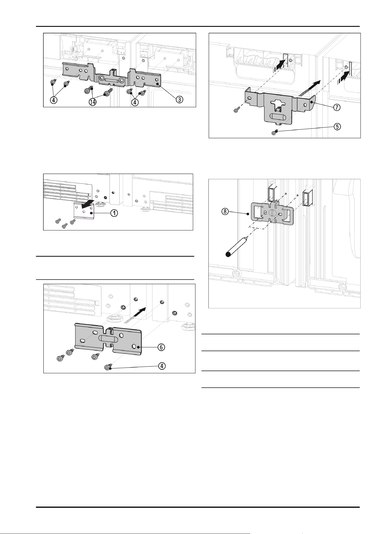
Fig. 13 Example illustration
u
Slide the bracket Fig. 13 (3) onto the pins with the spacer
between the appliances. Loosely screw in the brackets
alternately right and left with four screws Fig. 13 (4) and
the previously removed earthing screws Fig.13(14).
u
If necessary: Check the appliance is stood straight by
laying a spirit level on the top of the appliance.
Bottom front of the appliance:
u
Remove the existing covers.
Fig. 14
u
If the metal plate Fig. 14 (1) is installed, unscrew the
metal plate.
Note
If you want to transport the appliance or set it up as an
individual appliance, you must re-attach the metal plate.
Fig. 15 Example illustration
u
Slide the bracket Fig. 15 (6) on with the spacer between
the appliances and screw in loosely with the 4 screws
Fig. 15(4).
u
If necessary: Set up the appliances so that they are level.
u
Tighten the screws firmly at the top and bottom.
Top rear of the appliance:
Fig. 16 Example illustration
u
Slide the bracket Fig. 16 (7) onto the appliance ceiling
with the lugs and with the spacer between the appli‐
ances. Screw in firmly with 2 screws Fig. 16(5).
Bottom rear of the appliance:
Fig. 17 Example illustration
u
Slide the bracket Fig. 17 (8) on with the slots over the
retainer for the wall spacers.
Note
Holes for the screws must be pre-drilled.
u
Mark the position of the holes to be drilled with a pencil.
u
Remove the bracket again.
Note
Only drill through the metal plate. Drill depth approx. 1mm.
Side by side assembly
6 * Depending on model and options
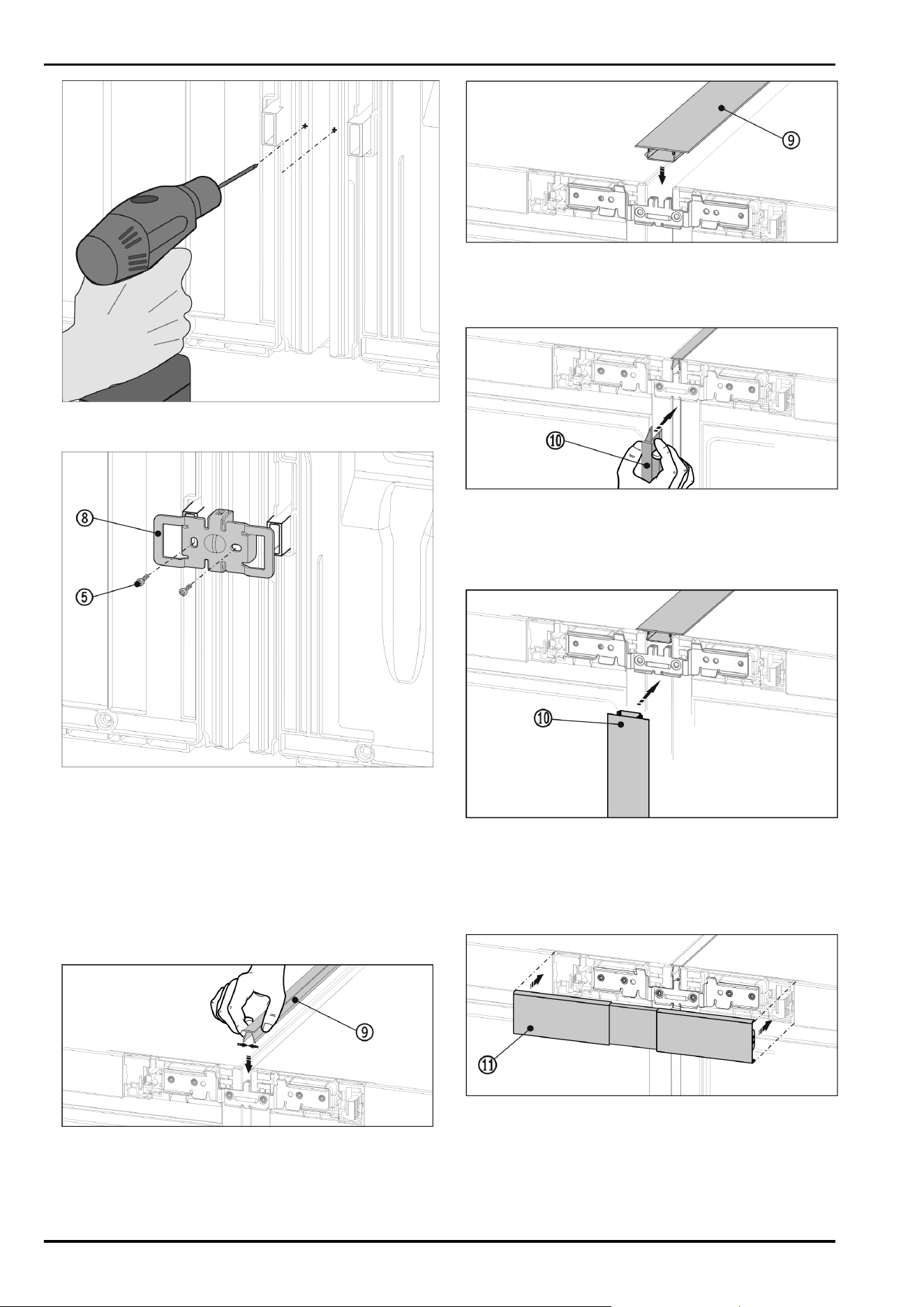
Fig. 18
u
Pre-drill the screw holes with a 3mm bit and deburr.
Fig. 19 Example illustration
u
Slide the bracket Fig. 19 (8) on once more with the slots
over the retainer for the wall spacers.
u
Screw in tightly with the 2 screws Fig. 19(5).
Before fitting the top and front cover strips, push the two
bars together over the whole length. The strips can be
inserted more easily into the gap. Use a soft cloth to push
the strips in to avoid dents in the surface of the cover strips.
Press the strips into the gap carefully and evenly in order to
achieve an optimum bond.
For appliances with lever handle
Fig.20
u
On the top press the short cover strip Fig. 20 (9) into the
horizontal gap.
For appliances with recessed grip
Fig.21
u
On the top press the short cover strip Fig. 21 (9) into the
horizontal gap.
For appliances with lever handle
Fig.22
u
On the front, press the long cover strip Fig. 22 (10)
into the vertical gap. Ensure that the strip rests on the
connecting plate.
For appliances with recessed grip
Fig.23
u
On the front, press the long cover strip Fig. 23 (10)
into the vertical gap. Ensure that the strip rests on the
connecting plate.
u
Take off the protective film from the cover strip.*
Top front of the appliance:
Fig. 24 Example illustration
u
Snap the top cover Fig. 24 (11) onto the still open gap
between the two control panel trims. Make sure that
the outer sides of the cover form a flush finish with the
control panel trims.
Bottom front of the appliance
Side by side assembly
* Depending on model and options 7
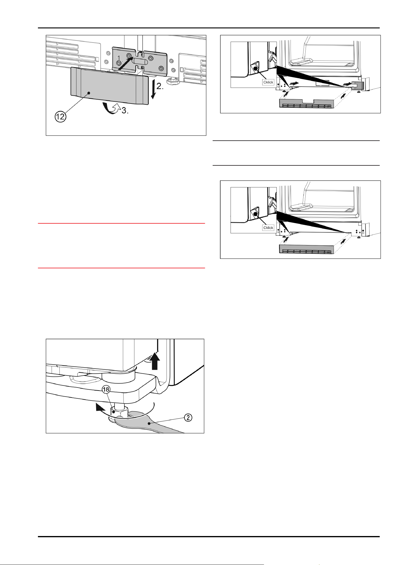
Fig. 25 Example illustration
u
Place the bottom cover Fig. 25 (12) onto the bracket from
the front Fig. 25 (1), slide it down Fig. 25 (2) and snap it in
at the bottom Fig.25(3).
u
To disassemble the cover, insert a screwdriver at the
bottom on the side below the cover and release both
lower hooks. The cover can swing out upwards.
u
Connect the combination electrically. See the installation
guide.
Appliances with IceMaker or InfinitySpring:
u
Connect the appliance to the fixed water connection. See
the installation guide.
NOTICE
Risk of damage when moving the combined SBS appliance!
The combined SBS appliance is heavy once assembled. The
appliance may be dented by improper movement.
u
Observe the information given on moving the appliance
(see above).
u
Carefully push the SBS combination into the specified
position.
u
If necessary, align the SBS combination using the level‐
ling feet.
u
Then prop up the door: Lower outer adjusting feet on the
bearing bracket until they are resting on the floor.
The doors can be straightened at height on the outer lower
bearing brackets:
u
Open the door to 90°.
Fig. 26
u
To lift the door, unscrew the adjusting foot Fig. 26 (18)
clockwise using the supplied open-ended spanner
Fig. 26 (2) until the foot makes contact with the floor.
Then continue turning until the door is adjusted to
the right height. When delivered, the bearing pin is
completely screwed in.
Fit decorative base trim.
After you have assembled and straightened out the appli‐
ances, the base trims can be fitted at the bottom of the
appliances. The base trims are decorative and will not affect
the functionality of the appliances.
For appliances with bottom soft stop mechanism
Fig.27
u
Attach the base trim to the bottom of the appliance in
the recess.
Note
The base trim must be pushed to a little behind the bearing
bracket cover.
For appliances without bottom soft stop mechanism
Fig.28
u
Secure the base trim recess at the bottom of the appli‐
ance, as shown in the figure.
Side by side assembly
8 * Depending on model and options

Side by side assembly
* Depending on model and options 9

home.liebherr.com/fridge-manuals
Side-by-Side combinations
Issue date: 20240216
Part number index: 7086159-00
Liebherr-Hausgeräte GmbH
Memminger Straße 77-79
88416Ochsenhausen
Deutschland
