0
MOTORIZED SMART UNDER DESK
BIKE FOR LEGS AND ARMS
SF-B0960 SMART
USER MANUAL
DO NOT STAND ON THE UNIT!
IMPORTANT! Please retain owner’s manual for maintenance and adjustment instructions.
Your satisfaction is very important to us, PLEASE DO NOT RETURN UNTIL YOU HAVE
CONTACTED US: support@sunnyhealthfitness.com or 1- 877 - 90SUNNY (877-907-8669).

1
IMPORTANT SAFETY INFORMATION
Thank you for purchasing the Motorized Smart Under Desk Bike For Legs And Arms. Please
read the operating instructions carefully before use, especially the safety precautions.
When using an electrical appliance, basic precautions should always be followed, including the
following:
Read all instructions before using this appliance.
DANGER – To reduce the risk of electric shock:
Always unplug this appliance from the electrical outlet immediately after using and before
cleaning.
WARNING – To reduce the risk of burns, fire, electric shock, or injury to person(s):
1. This product’s rated voltage is 120V, rated power is 220W.
2. Before starting any exercise program, you should consult your physician to determine if you
have any medical or physical conditions that could put your health and safety at risk or
prevent you from using the equipment properly. Your physician’s advice is essential if you
are taking medication that affects your heart rate, blood pressure, or cholesterol level.
3. Be aware of your body’s signals. Incorrect or excessive exercise can damage your health.
Stop exercising if you experience any of the following symptoms: pain, tightness in your
chest, irregular heartbeat, shortness of breath, lightheadedness, dizziness, or feelings of
nausea. If you do experience any of these conditions, you should consult your physician
before continuing with your exercise program.
4. The equipment is not suitable for therapeutic use.
5. Keep children and pet away from this machine. The equipment is designed for adult use
only.
6. Do not place fingers or objects into the moving parts of the equipment.
7. Use the equipment on a solid, flat level surface with a protective cover for your floor or
carpet. To ensure safety, the equipment should have at least 2 feet (60 cm) of free space
all around it.
8. An appliance should never be left unattended when plugged in. Unplug from outlet when
not in use, cleaning and before putting on or taking off parts.
9. Do not stand on the elliptical, only use the elliptical while sitting.
10.Always use the equipment as indicated. If you find any defective components while
assembling or checking the equipment, damages or if you hear any unusual noises coming
from the equipment during exercise, discontinue use of the equipment immediately and do
not use until the problem has been rectified.
11.Never operate the appliance with the air openings blocked. Keep the air openings free of
lint, hair, and other objects.
12.Your product is intended for use in cool, dry conditions. You should avoid storage in
extreme cold, hot or damp areas as this may lead to corrosion and other related problems.
13.Keep the appliance dry. Do not expose appliance to wet, moisture and humid environment.
14.Use this appliance only for its intended use as described in this manual. Do not use
attachments not recommended by the manufacturer. If a product is modified or altered, it
may void the warranty.
SAVE THESE INSTRUCTIONS
2
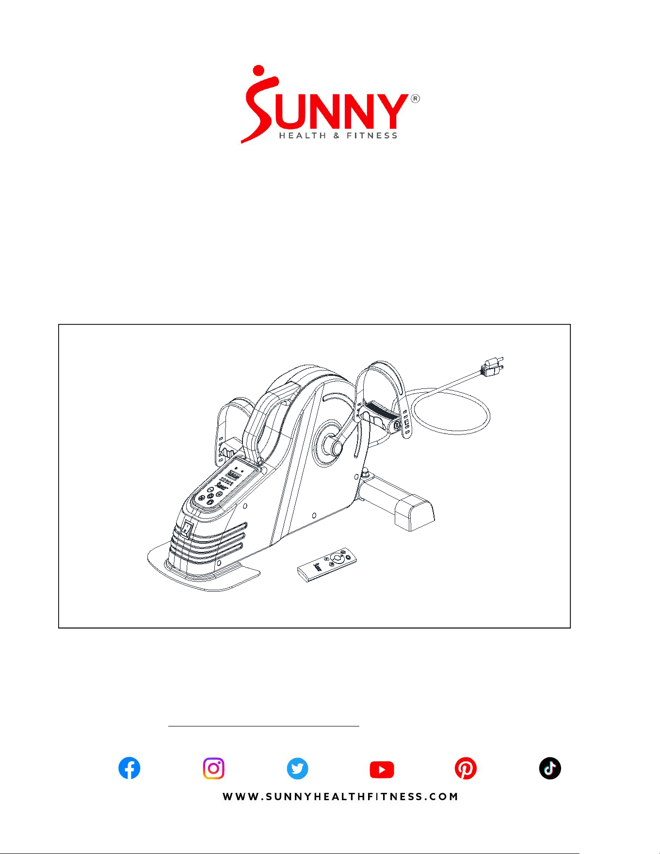
PRE-ASSEMBLY CHECK LIS
1 2
4
A
B
C
D
7L/R
11-1
19
HARDWARE PACKAGE SF-B0960/SF-B0960 SMART
STEP2
STEP1
#14 M8*42 2PCS #17 M8 2PCS
#15 ID8.2*OD16*1.5 2PCS
#18 M6*16 3PCS
#39 S13-S14-S15 1PC
#40 S17-S19 1PC
No.
Description
Spec.
Qty.
No.
Description
Spec.
Qty.
1
Main Frame
1
19
Rear Fixed Bottom Plate
1
2
Front Stabilizer
1
A
Hardware Package
1
4
Power Cord
1
B
Battery
AAA
2
7L
Left Pedal
1
C
Thank You Card
1
7R
Right Pedal
1
D
User Manual
1
11-1
Remote Control
1
3
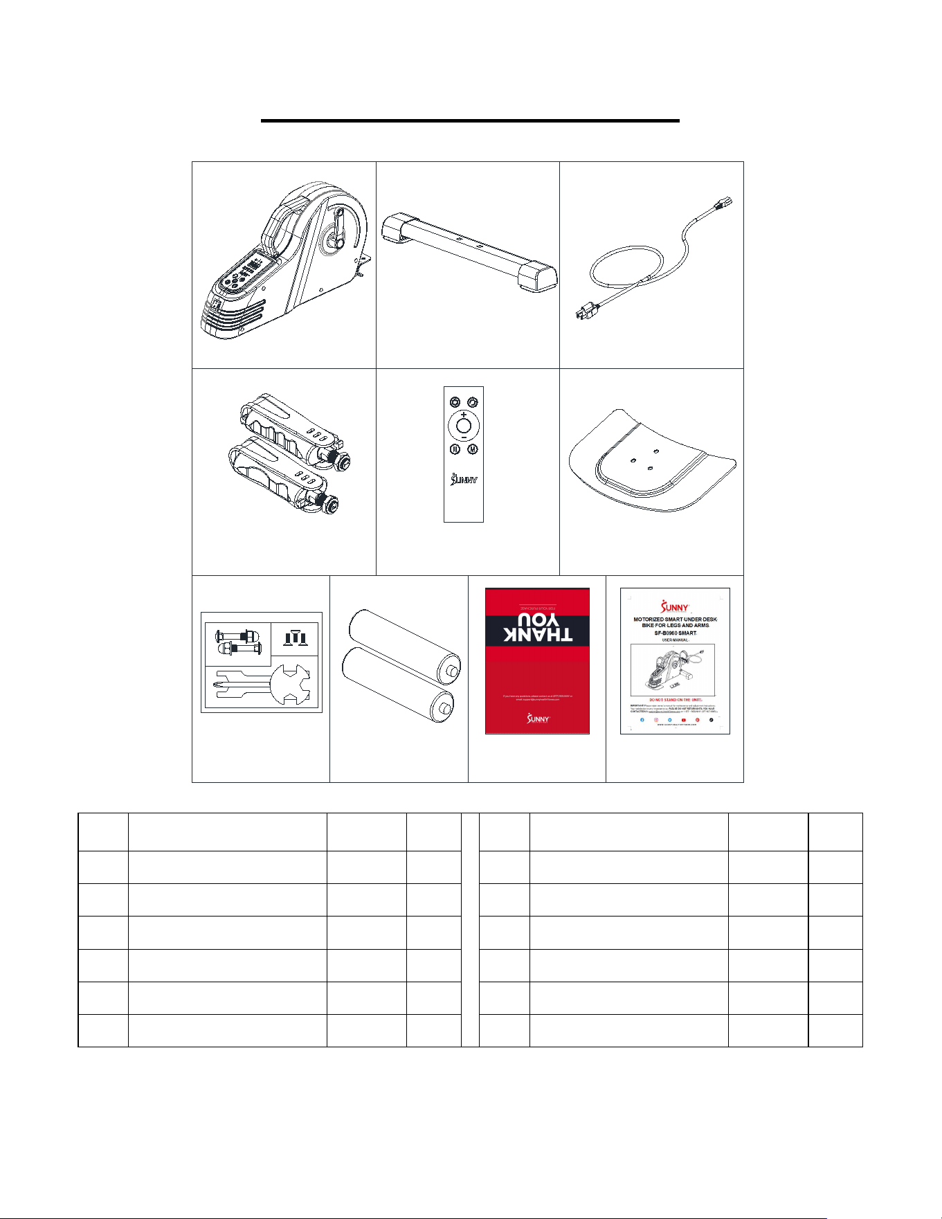
HARDWARE PACKAGE
Ordering Replacement Parts (U.S. and Canadian Customers only)
Please provide the following information in order for us to accurately identify the part(s) needed:
The model number (found on cover of manual)
The product name (found on cover of manual)
The part number found on the “EXPLODED DIAGRAM” (page 20) and “PARTS LIST”
(page 19).
#14 M8*42 2PCS
#18 M6*16 3PCS
#15 ID8.2*OD16*1.5 2PCS
#17 M8 2PCS
#39 S13-S14-S15 1PC
#40 S17-S19 1PC
4
ASSEMBLY INSTRUCTIONS
We value your experience using Sunny Health and Fitness products. For assistance with parts or
907-8669).
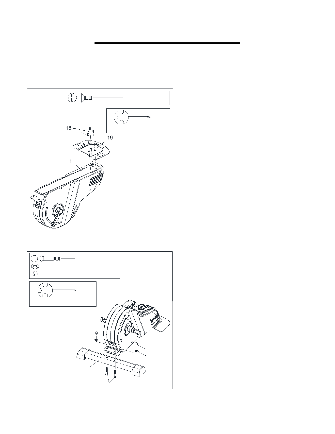
STEP 1:
Attach Rear Fixed Bottom Plate (No. 19) to
the Main Frame (No. 1) with 3 Bolts (No. 18).
Tighten and secure with Spanner (No. 39).
STEP 2:
Attach Front Stabilizer (No. 2) to the Main
Frame (No. 1) with 2 Carriage Bolts (No. 14),
2 Washers (No. 15), and 2 High Cap Nuts
(No. 17). Tighten and secure with Spanner
(No. 39).
#39 S13-S14-S15 1PC
#18 M6*16 3PCS
2
14
15
17
15
17
1
#39 S13-S14-S15 1PC
#14 M8*42 2PCS
#15 ID8.2*OD16*1.5 2PCS
#17 M8 2PCS
5
We value your experience using Sunny Health and Fitness products. For assistance with parts or
907-8669).
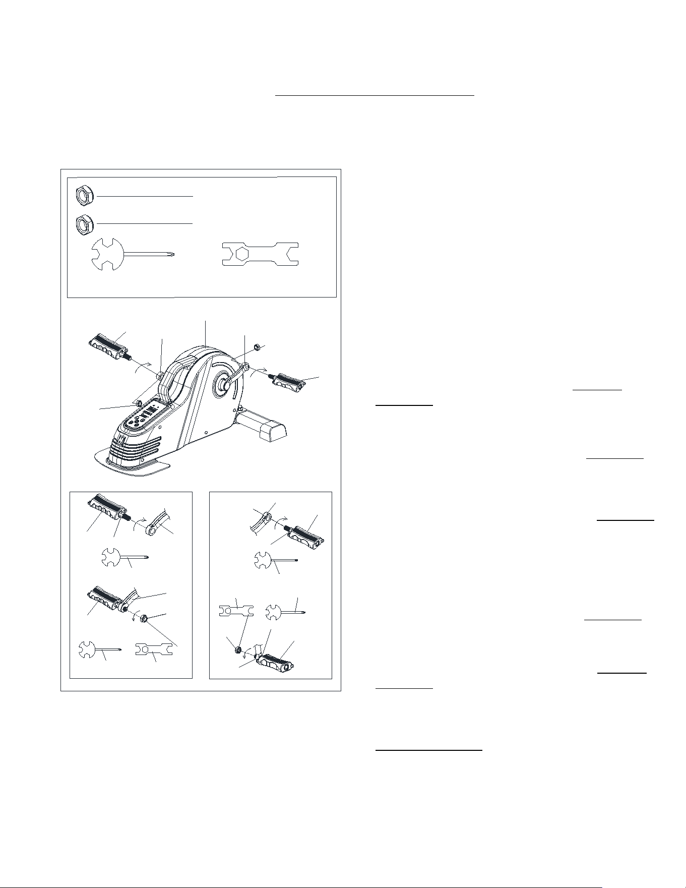
STEP 3:
NOTE: The Left & Right Pedals (No. 7L &
No. 7R) are marked “L” and “R” for Left and
Right.
WARNING! Read instructions carefully as
improper assembly may cause permanent
damage to your bike.
Remove the 2 Left & Right Nylon Nuts (No.
21L & No. 21R) located on the Left & Right
Pedals (No. 7L & No. 7R).
Align the Left Pedal (No. 7L) with the Left
Crank (No. 3L) at 90°. Gently insert the Left
Pedal (No. 7L) into the Left Crank (No. 3L)
and turn the Left Pedal (No. 7L) counter-
clockwise as tightly as you can with your
hand. Use Spanner (No. 39) to tighten and
secure.
Turn the Left Nylon Nut (No. 21L) clockwise
as tightly as you can with your hand. Use
Spanner (No. 39) to hold the pedal bolt on the
Left Pedal (No. 7L) and use Spanner (No. 40)
to turn the Left Nylon Nut (No. 21L) clockwise
at the same time, until it is tightened on to the
Left Crank (No. 3L).
Align the Right Pedal (No. 7R) with the Right
Crank (No. 3R) at 90°. Gently insert the Right
Pedal (No. 7R) into the Right Crank (No. 3R)
and turn the Right Pedal (No. 7R) clockwise
as tightly as you can with your hand. Use
Spanner (No. 39) to tighten and secure.
Turn the Right Nylon Nut (No. 21R) counter-
clockwise as tightly as you can with your hand.
Use Spanner (No. 39) to hold the pedal bolt on
the Right Pedal (No. 7R) and use Spanner
(No. 40) to turn the Right Nylon Nut (No. 21R)
counter-clockwise at the same time, until it is
tightened on to the Right Crank (No. 3R).
#39 S13-S14-S15 1PC #40 S17-S19 1PC
S19
3L
21L
39
3L
7L
39
40
3R
7R
39
3R
7R
21R
39
40
S15
S15
S19
S15
S15
S19
7L
#21R 1/2"-20 1PC
#21L 1/2"-20 1PC
21L
3L
7L
21R
3R
7R
1
6
We value your experience using Sunny Health and Fitness products. For assistance with parts or
907-8669).
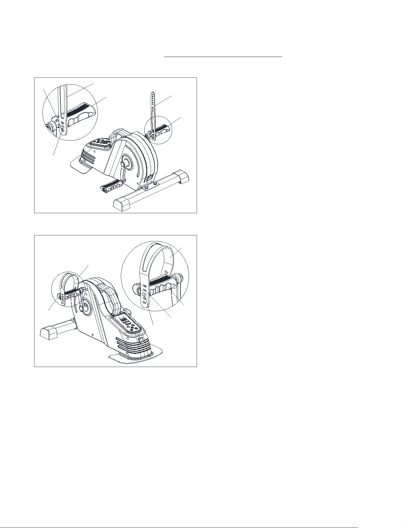
STEP 4:
Insert the fixing hole (#A) of the Pedal Strap
(#41-1) into the card slot (#7L-1) of the Left
Pedal (#7L).
Insert the fixing hole (#B) of the Pedal Strap
(#41-1) into the card slot (#7L-2) of the Left
Pedal (#7L).
NOTE:The position of fixing holes and card
slots can be adjusted according to the size of
your feet.
41-1
41-1
7L
7L-1
A
7L
41-1
7L
B
7L-2
7L
41-1
7
We value your experience using Sunny Health and Fitness products. For assistance with parts or
907-8669).
7R
41-1
7R
41-1
A
7R-1
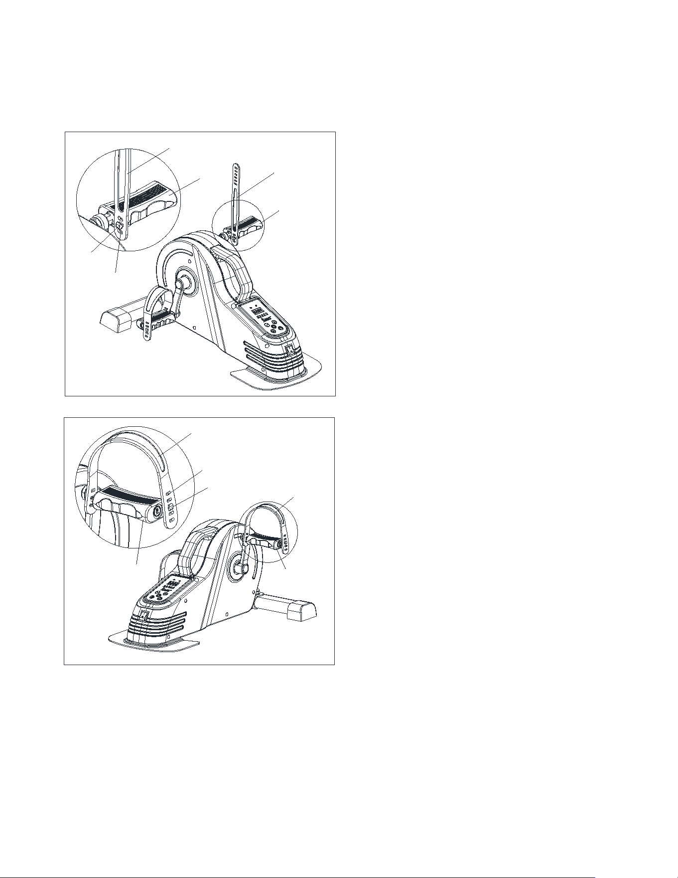
STEP 5:
Insert the fixing hole (#A) of the Pedal Strap
(#41-1) into the card slot (#7R-1) of the Right
Pedal (#7R).
Insert the fixing hole (#B) of the Pedal Strap
(#41-1) into the card slot (#7R-2) of the Right
Pedal (#7R).
NOTE:The position of fixing holes and card
slots can be adjusted according to the size of
your feet.
7R
41-1
41-1
7R
B
7R-2
8
We value your experience using Sunny Health and Fitness products. For assistance with parts or
907-8669).
1
13
4
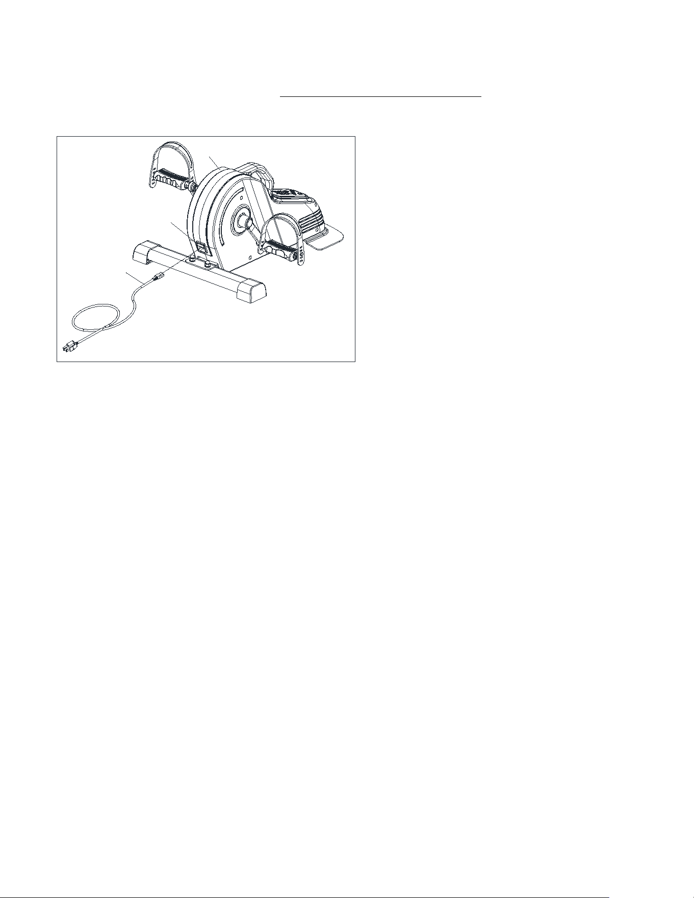
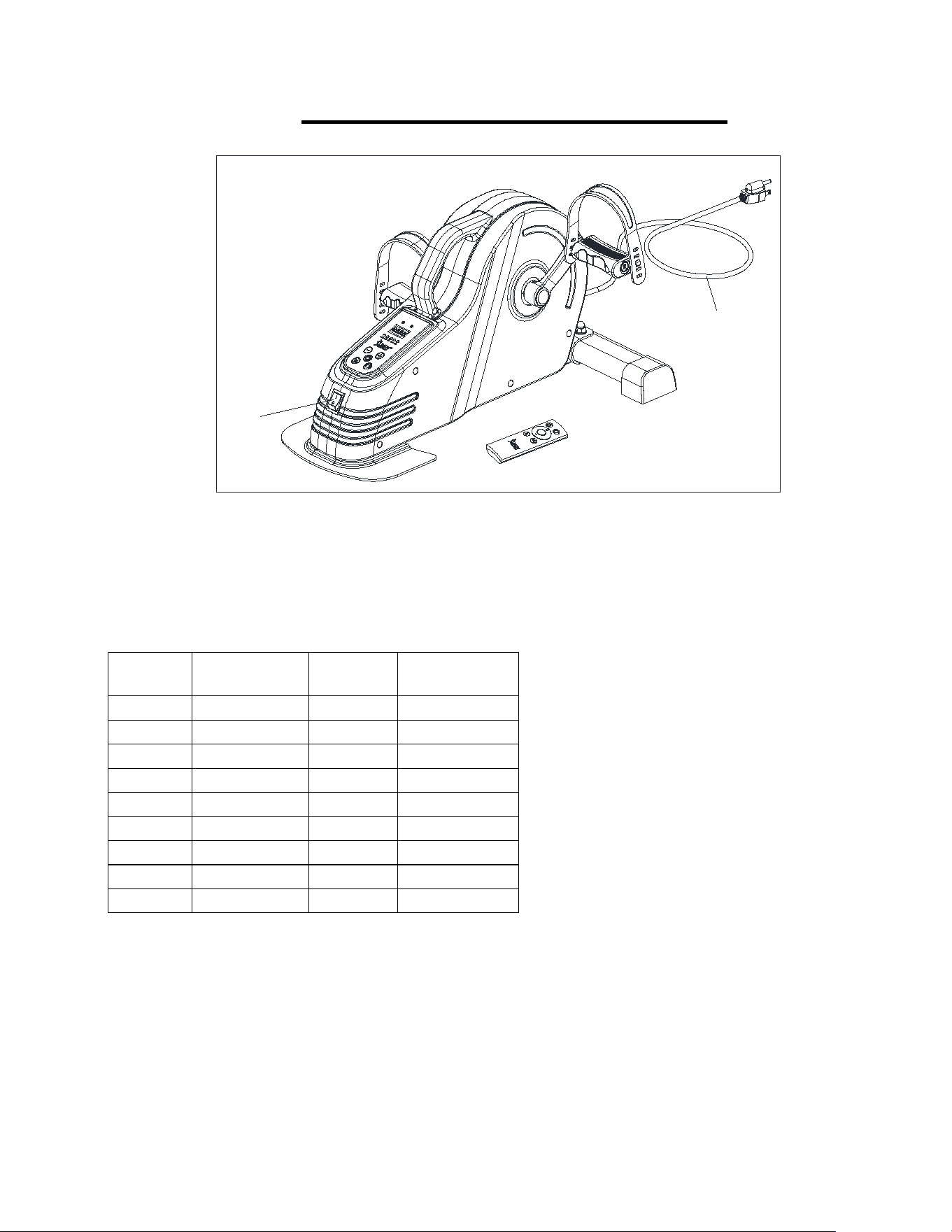
STEP 6:
Plug the Power Cord (No. 4) into the
Outlet (No. 13) on the Main Frame (No.
1).
The assembly is complete!
9
IMPORTANT ELECTRICAL INFORMATION
WARNING:
This cycle requires a power source of 120V in order to properly operate. For your safety as
well as the safety of others, please verify that the power source is correct before powering in
the equipment. Any power supply source above or below this level could cause significant
damage to the equipment and/or user.
GROUNDING METHODS:
This cycle must be grounded. Should the cycle malfunction or breakdown, grounding provides
a path of least resistance for electric current to reduce the risk of electric shock. This product is
equipped with a plug that has an equipment-grounding conductor and a grounding plug. The
plug must be plugged into an appropriate outlet that is properly installed and grounded in
accordance with all local codes and ordinances.
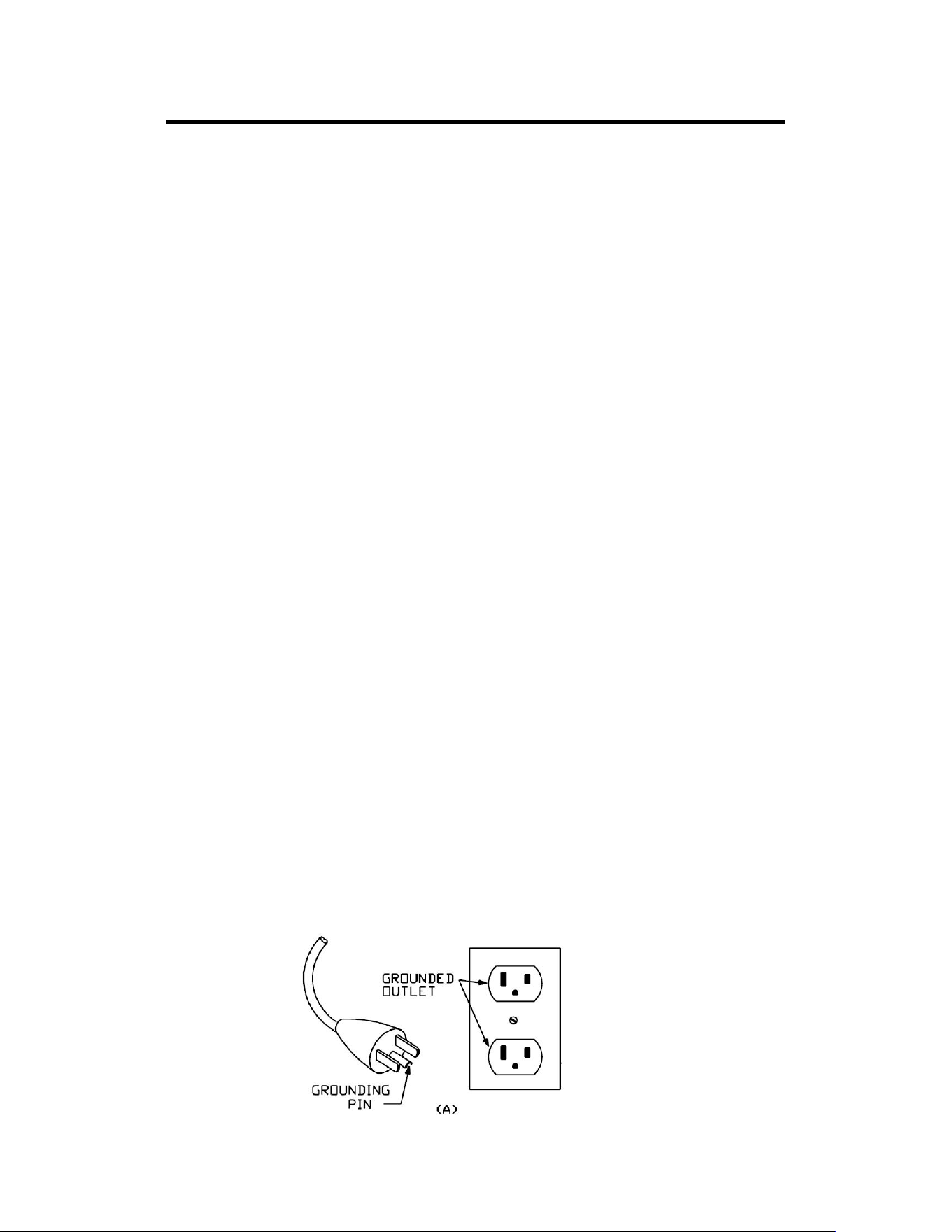
This cycle is for use on a nominal 120V circuit and has a grounding plug that looks like the
plug illustrated in sketch A. Ensure that the cycle is connected to an outlet with the same
configuration as the plug. Do not use an adaptor for this product.
DANGER:
Improper connection of the equipment can result in risk of electric shock. Check with a
qualified electrician or serviceman if you are unsure whether the product has been properly
grounded. Do not modify the plug provided with the product. If it will not fit the outlet, have a
proper outlet installed by a qualified electrician.
WARNING!
1. NEVER use a ground fault circuit interrupt (GFCI) wall outlet with this cycle.
2. NEVER operate the cycle using a generator or UPS power supply.
3. NEVER remove any cover on this cycle without first disconnecting the Power Cord (No. 4).
4. NEVER expose the cycle to rain or moisture. This cycle is not designed for outdoor use or
use in any high humidity environment.
GROUNDING METHOD
10
BATTERY INSTALLATION & REPLACEMENT
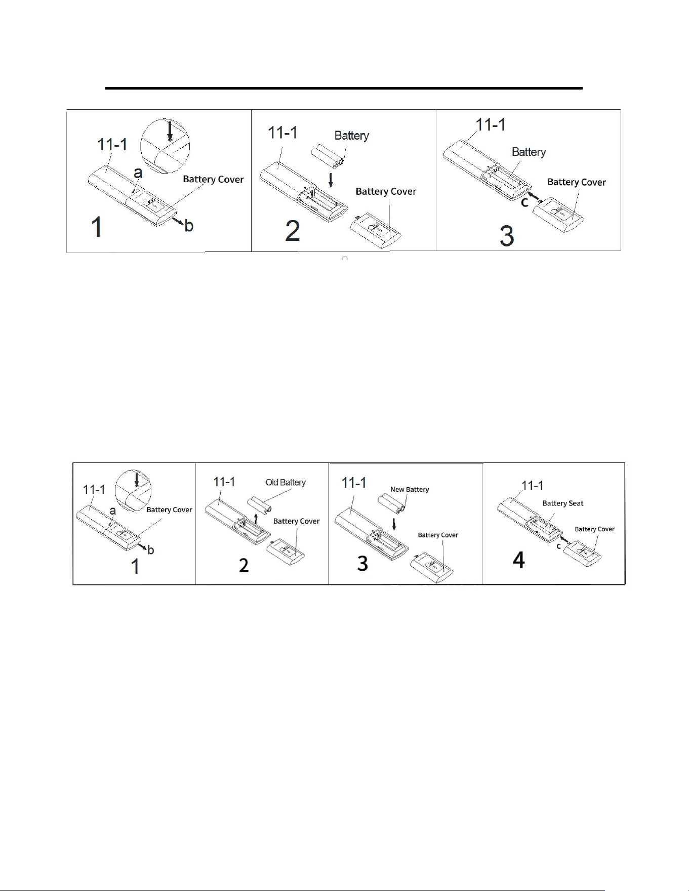
BATTERY INSTALLATION:
1. Press point a with a pen or other something sharp, then push down the battery cover on
the back of the Remote Control (No. 11-1) to remove the battery cover.(as shown by the
arrow b)
2. Take out 2 AAA batteries from the manual bag. Install 2 AAA batteries into the battery seat
on the back of the Remote Control (No. 11-1). Pay attention to the battery + and – ends
before installing.
3. Put the battery cover back to the Remote Control (No. 11-1) and push the cover up to
tighten it on the back of the Remote Control (No. 11-1) (as shown by the arrow c).
The installation is complete!
BATTERY REPLACEMENT:
1. Press point a with a pen or other something sharp , then push down the battery cover on
the back of the Remote Control (No. 11-1) to remove the battery cover.(as shown by the
arrow b).
2. Take out the old batteries from the battery seat.
3. Install 2 AAA batteries into the battery seat on the back of the Remote Control (No. 11-1).
Pay attention to the battery + and – ends before installing.
4. Put the battery cover back to the Remote Control (No. 11-1) and push the cover up to
tighten it on the back of the Remote Control (No. 11-1) (as shown by the arrow c).
The replacement is complete!
Dispose the old battery according to your regional guidelines.
11
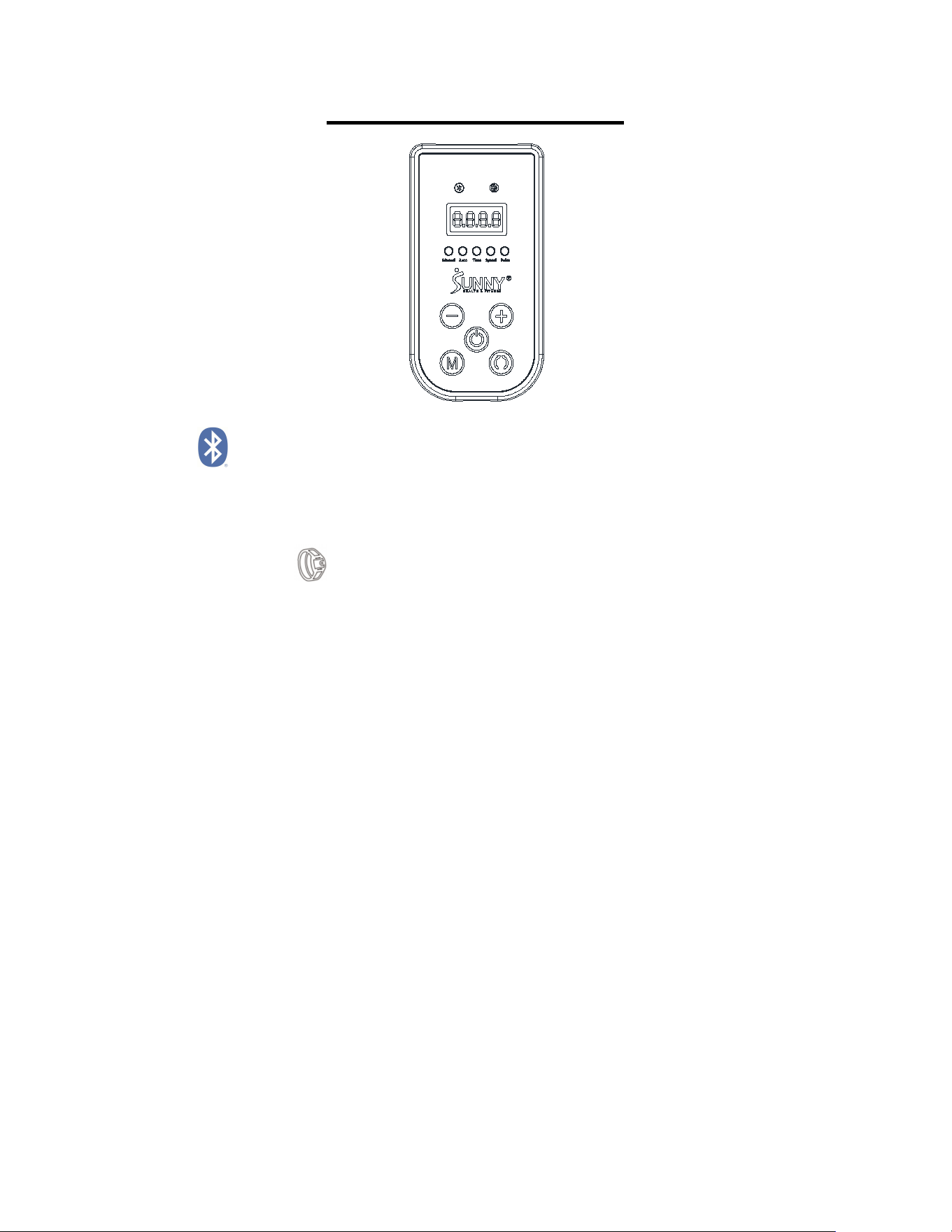
DISPLAY CONSOLE
BLUETOOTH :
1. The Bluetooth icon will flash when the console is on. If no Bluetooth connection is
established within 3 minutes, the Bluetooth icon will turn off.
2. The Bluetooth icon will stay on when it is connected.
WIRELESS HEART RATE :
1. The wireless heart rate icon will always light up when the heart rate monitor is connected.
2. The wireless heart rate icon will flash when the console is on. If the heart rate monitor is not
connected within 3 minutes, the wireless heart rate icon will turn off. But the heart rate
monitor can also be connected.
3. The heart rate monitor will disconnect when the console power off. The heart rate icon will
turn off and the heart rate function will temporary failure.
4. The heart rate monitor will disconnect when press and hold the START/PAUSE button for 6
seconds or more. The heart rate icon will turn off and the heart rate function will temporary
failure.
NOTE: It needs to reawaken the heart rate icon to re-connect the heart rate monitor when the
heart rate function temporary failure.
Ways to wake up the heart rate icon: A. Press the START button when the console is in
paused or stopped state; B. The APP is successfully connected and the sports interface is
entered when the console is in suspended or stopped state; C. Press the MODE button or
switch the MODE in the APP when the console is in running state.
NOTE: The heart rate monitor is not included. Wireless heart rate function works with SunnyFit
Heart Rate Monitor HR200.
ELECTRICAL INFORMATION
Rated Voltage: 120V
12
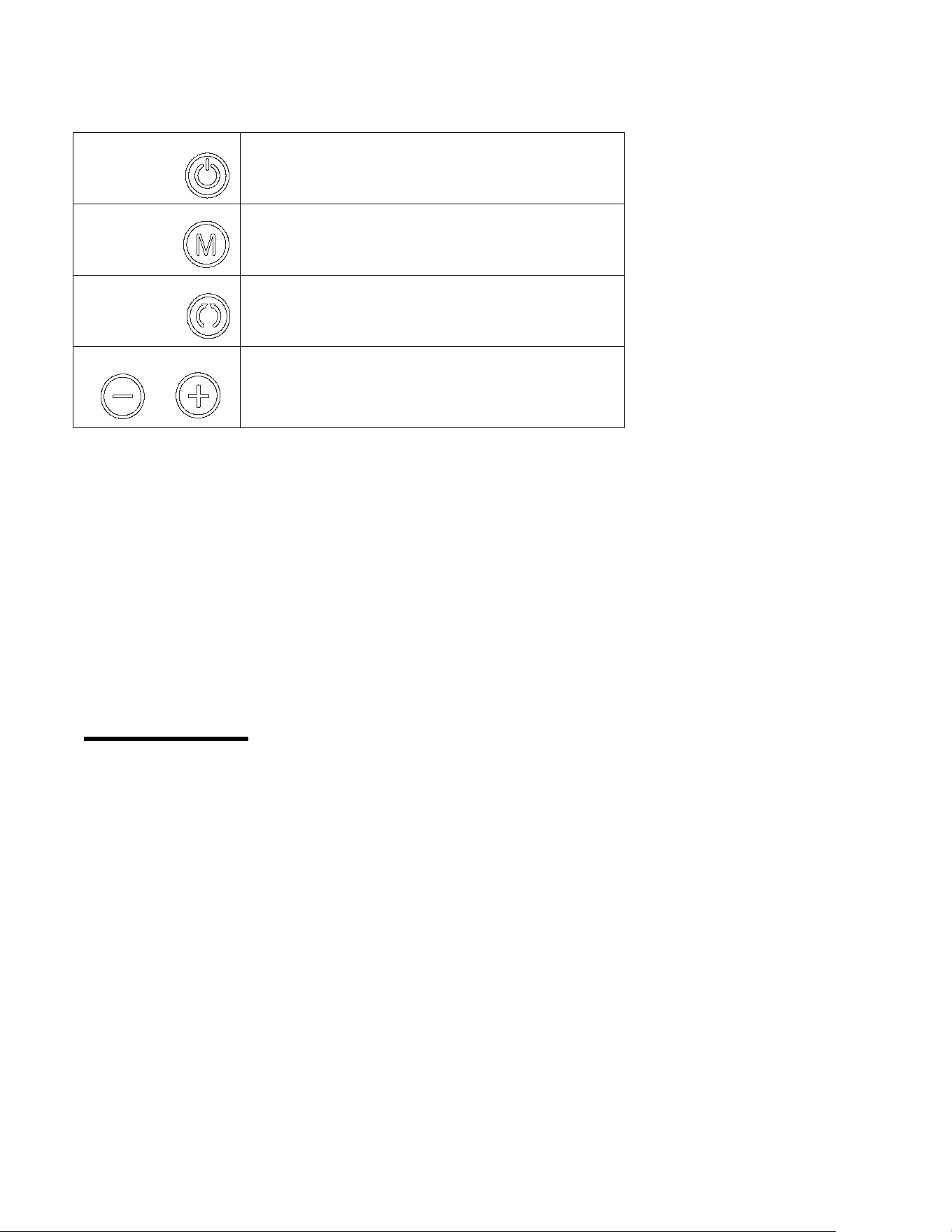
FUNCTION KEYS
Start/Pause
Start and pause bike
Mode
Changes between automatic and manual
Direction
Changes the direction forward or backward
Speed+/-
Select key for increasing or decreasing
speed (18 speed levels)
WARNINGS AND INSTRUCTIONS
Do not stand on the bike. Only use while seated in a chair.
If bike is tilted over 45 degrees, it will auto stop.
If bike detects problems during exercise, it will auto stop within 10 seconds.
Failure to follow above all warnings and instructions could result in serious injury or death, and
cause the machine to stop and make an alarm sound. When the display console shows “ERR”,
press the Start/Pause button to reset automatically. If the “ERR” no longer appears, continue
to use normally. If the code continues to appear, please contact customer service.
TECHNICAL DATA
Connectivity: Bluetooth LE
Frequency Range: 2400~2483.5Mhz
Transmitting Power: 0dBm
13
OPERATING INSTRUCTIONS
1. Plug in the Power Cable (No. 4). Turn on the Power Switch (No. 5). The bike will beep
and LED display will show “OFF“. This is standby mode.
2. Press the Start/Pause button on the console or the remote control to start the bike, it will
begin in manual mode. Display will show L1.
3. Under the manual mode, press the Speed “+” button to increase the speed from L1 to L18.
Or press the Speed “–” button to decrease the speed from L18 to L1.
Level
Speed
(MPH)
Level
Speed
(MPH)
L1
0.674
L10
1.412
L2
0.737
L11
1.496
L3
0.843
L12
1.559
L4
0.948
L13
1.622
L5
1.032
L14
1.685
L6
1.074
L15
1.749
L7
1.180
L16
1.791
L8
1.285
L17
1.854
L9
1.369
L18
1.896
1. Under the manual mode, press the Direction button to change the direction forward or
backward.
2. Under the manual mode, the LED display will alternate display between speed level, speed,
time and pulse (pulse only occurs when the heart rate is detected).
3. Press the Mode button on the console or the remote control to change the mode from
manual mode to auto mode P1, press again from P1 to P2 mode, press again from P2 to
P3, then press again from P3 back to the manual mode.
4. Under the automatic mode, there are P1/P2/P3 modes included. Different modes have
different speeds and working directions, see below details.
5
4

14
P1 MODE
:
Based on speed Level 1, the pedals move 13 times forward, 13 times
backwards, 13 times forward based, 13 times backwards and so on.
P2 MODE: The pedals move forward first then the speed will be increasing from Level 1 to
Level 9 gradually. When the speed reaches Level 9, the speed will be decreasing from
Level 9 to Level 1. When the speed reaches Level 1, the pedals change to move
backwards and the speed will be increasing from Level 1 to Level 9 gradually. When the
speed reaches Level 9, the speed will be decreasing from Level 9 to Level 1. When the
speed reaches Level 1, the pedals change to move forward and repeats the operation.
P3 MODE:The pedals move forward first then the speed will be increasing from Level 1
to Level 18 gradually. When the speed reaches Level 18, the speed will be decreasing
from Level 18 to Level 1. When the speed reaches Level 1, the pedals change to move
backwards and the speed will increasing from Level 1 to Level 18 gradually, when the
speed reaches Level 18, the speed will be decreasing from Level 18 to Level 1. When the
speed reaches Level 1, the pedals change to move forward and repeats the operation.
5. The machine will stop automatically after working continuously for 30 minutes. At the stop
moment, the LED display will show “OFF” then show the exercise mode and dates.
NOTE: After finish using, please turn off the switch and disconnect the power.
15
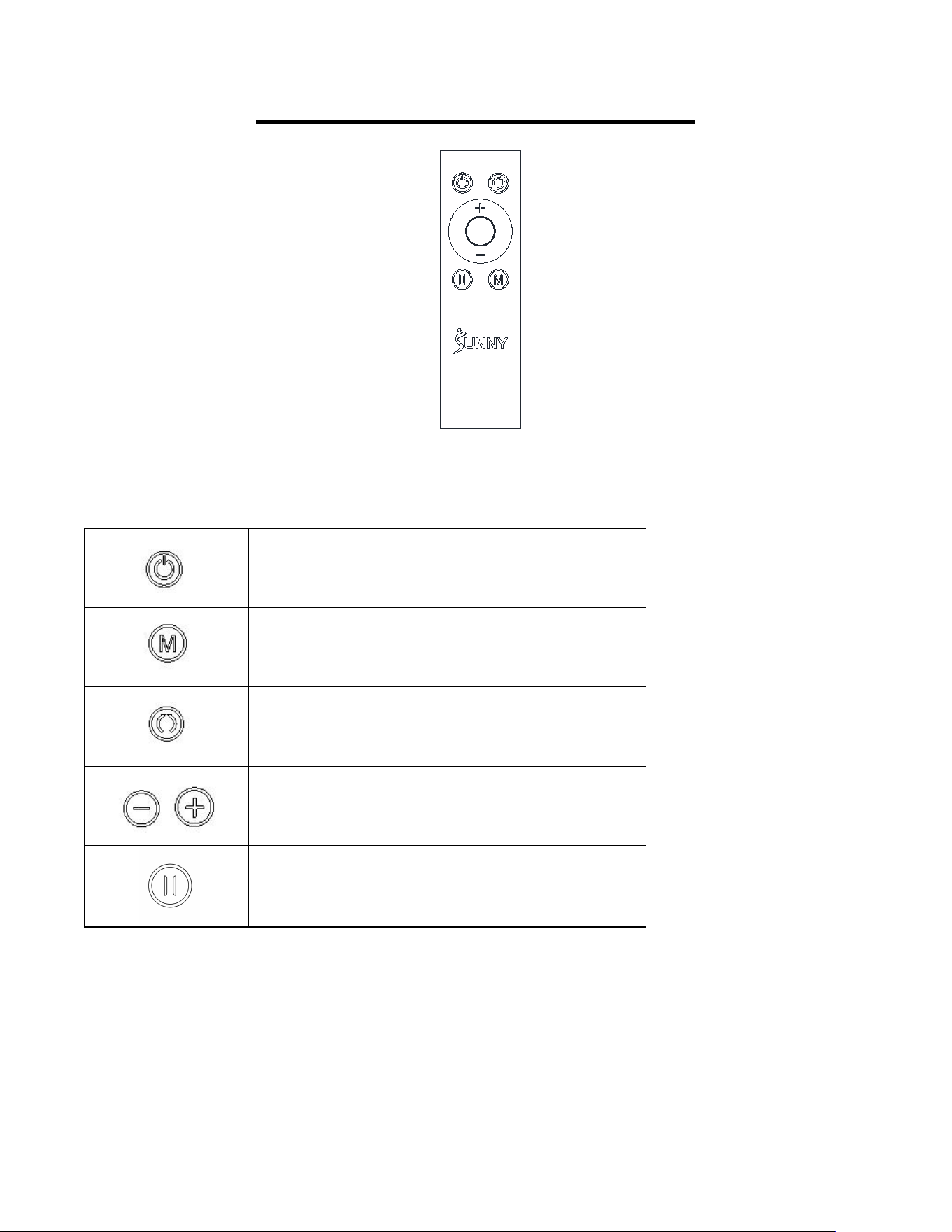
DISPLAY REMOTE CONTROL
FUNCTION KEYS
Start/Pause: Start and pause machine
Mode: Changes between automatic and
manual
Direction: Changes the direction forward or
backward
Speed: Select+ key for increasing or -key for
decreasing speed (18 speed levels)
Pause
REMOTE CONTROL NOTICE:
If the Remote Control (No. 11-1) does not activate the Motorized Smart Under Desk Bike for
Legs and Arms, or if you have a replacement remote, the Remote Control (No. 11-1) and
Motorized Smart Under Desk Bike for Legs and Arms will need to be paired.
REMOTE CONTROL PAIRING METHOD:

16
1. Restart the Motorized Smart Under Desk Bike for Legs and Arms, press and hold down the
Mode button and Direction button at the same time, you will hear three “beep” sounds.
2. Press and hold down the Mode button on the Remote Control (No. 11-1) immediately for
about 3 seconds. Hearing a "Beep" indicates that the pairing is successful. During the pairing,
the Remote Control (No. 11-1) should be as close to the Motorized Smart Under Desk Bike
for Legs and Arms as possible.
Caution: The user is cautioned that changes or modifications not expressly approved by the
party responsible for compliance could void the user's authority to operate the equipment.
This device complies with Part 15 of the FCC Rules. Operation is subject to the following two
conditions: (1) this device may not cause harmful interference, and (2) this device must accept
any interference received, including interference that may cause undesired operation.
NOTE: This equipment has been tested and found to comply with the limits for a Class B
digital device, pursuant to Part 15 of the FCC Rules. These limits are designed to provide
reasonable protection against harmful interference in a residential installation. This equipment
generates, uses and can radiate radio frequency energy and, if not installed and used in
accordance with the instructions, may cause harmful interference to radio communications.
However, there is no guarantee that interference will not occur in a particular installation.
If this equipment does cause harmful interference to radio or television reception, which can be
determined by turning the equipment off and on, the user is encouraged to try to correct the
interference by one or more of the following measures:
-- Reorient or relocate the receiving antenna.
-- Increase the separation between the equipment and receiver.
-- Connect the equipment into an outlet on a circuit different from that to which the receiver is
connected.
-- Consult the dealer or an experienced radio/TV technician for help.
FCC Radiation Exposure Statement
This equipment complies with FCC radiation exposure limits set forth for an uncontrolled
environment. This equipment should be installed and operated with a minimum distance of
20cm between the radiator and your body.
This transmitter must not be co-located or operating in conjunction with any other antenna or
transmitter.
17
USER-MAINTENANCE INSTRUCTION
Caution:There are no serviceable parts in the appliance, any servicing should be performed
by an authorized service person.
When the appliance is not in use, disconnect the power supply, storage of the power cord and
the total appliance in a dry location where children cannot touch or in play area(s).
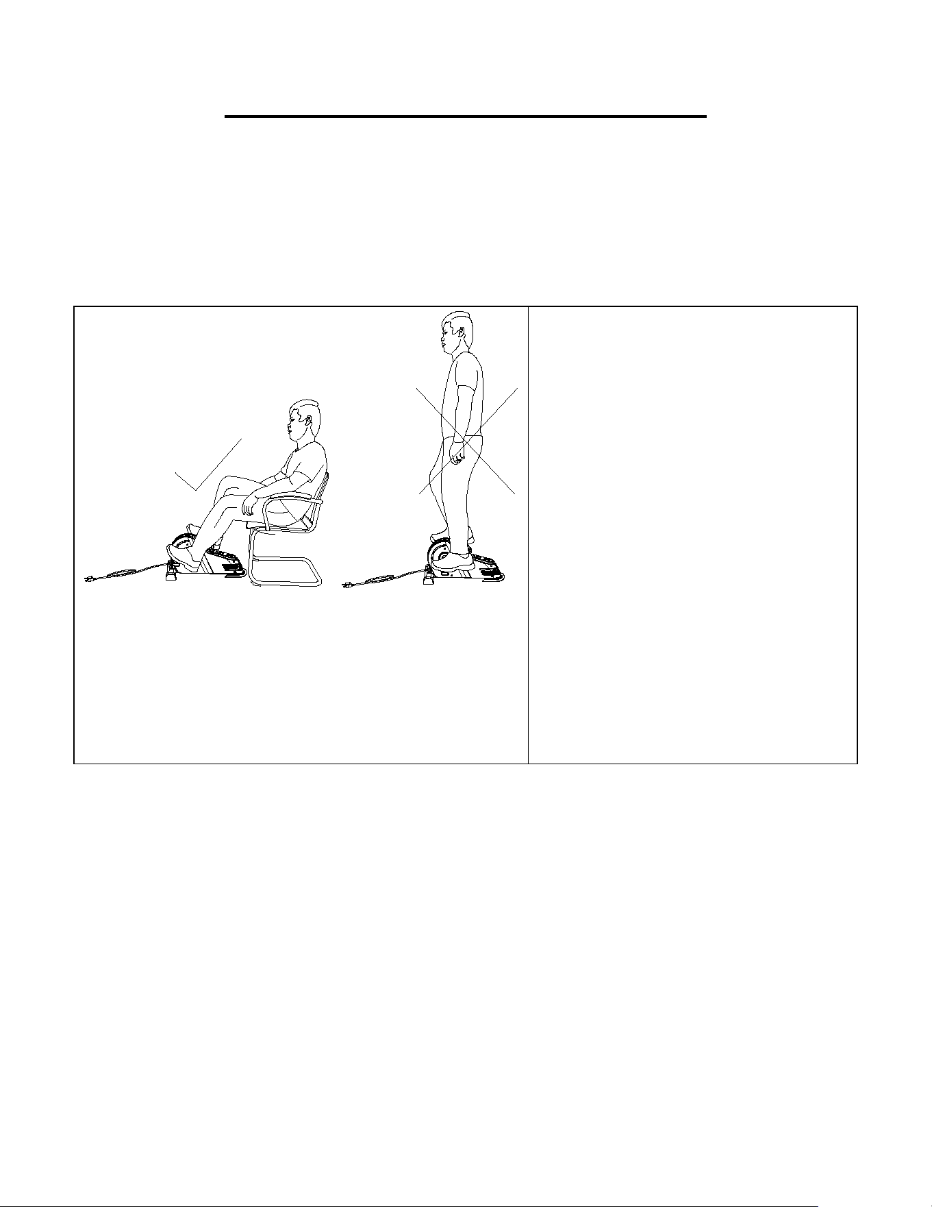
USE ONLY WHILE SITTING.
DO NOT STAND ON THE BIKE!
WARNING
The machine is intended to use in a
sitting position only. When using the
machine, keep the feet flat to avoid
rubbing against the floor. Do not stand
on the machine.
Failure to follow all warnings and
instructions could result in serious
injury or death.
18
APP CONNECTION:
Connect Smart Equipment to SunnyFit App:
1. Scan to download SunnyFit from the app store:
2. Ensure that the Bluetooth function is turned on from your mobile device.
3. If this is your first time using the SunnyFit app, follow the in-app instructions to register for your
free SunnyFit account and log in.
4. Begin any workout activity that matches your smart equipment, then follow the onscreen
prompts to search for and connect to your smart equipment.
5. When connected, your stats and records will be displayed at the end of your course/session,
and recorded in your account profile!
Troubleshooting:
If you are having trouble connecting your smart equipment, visit www.sunnyfit.com/guide or
scan the QR code below:
If you require additional support, please contact support@sunnyfit.com.

19
PARTS LIST
No.
Description
Spec.
Qty
No.
Description
Spec.
Qty
1
Main Frame
1
21L
Left Nylon Nut
1/2”-20
1
2
Front Stabilizer
1
21R
Right Nylon Nut
1/2”-20
1
3L
Left Crank
1
22
Screw
ST3.5*15
1
3R
Right Crank
1
23
Non-Slip Pad
1
4
Power Cord
1
24
Screw
ST4.2*15
10
5
Power Switch
1
25
Flange Nut
M10
2
6
Rubber Pad
2
26
End Cap
2
7L
Left Pedal
1
27
Spring Washer
Φ2.2*Φ3.4*0.8
1
7R
Right Pedal
1
28
3P Data Line
1
8L
Left Belt Cover
1
29
Sensor
1
8R
Right Belt cover
1
30
Screw
M3*8
2
9
Motor
1
31
Fixing Bolt
4
10
Console
1
32
6P Data Line
1
11-1
Remote Control
1
33
Screw
M5*16
6
12
Controller
1
34
Spring Washer
Φ2.7*Φ4.2*1.1
6
13
Outlet
1
35
Flat Washer
Φ5.5*Φ10*1
6
14
Carriage Bolt
M8*42
2
36
Screw
M4*10
1
15
Washer
ID8.2*OD16*1.5
2
37
Screw
M3*5
4
16
End Cap
2
38
Washer
Φ70*1.0
1
17
High Cap Nut
M8
2
39
Spanner
S13-S14-S15
1
18
Bolt
M6*16
3
40
Spanner
S17-S19
1
19
Rear Fixed Bottom Plate
1
41-1
Pedal Strap
277mm
2
20
EVA Non-Slip Pad
2
20
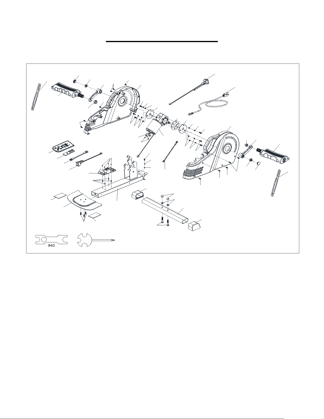
EXPLODED DIAGRAM
Version 1.2
8R
8L
16
24
24
24
13
6
6
29
30
33
34
35
36
27
23
22
2
15
17
1
8
#39
3
L
2
6
2
5
14
12
3
1
37
38
7L
41-1
41-1
20
25
26
3R
7R
21R
20
19
35
34
33
28
4
5
32
11-1
10
24
24
1
35
34
33
35
34
33
21L
24
24
9
16