Loading ...
Loading ...
Loading ...
Water pressure:
bar psi MPa
1.5 to 6.2 21.76 to 87.02 0.15 to 0.62
Water pressure if using the water filter:*
bar* psi* MPa*
2.8 to 6.2 40 to 90 0.28 to 0.62
If the pressure exceeds 0.62 MPa (6.2 bar): Connect a
pressure reducer.
Make sure that the following conditions are met:
q
The water pressure is correct.
q
Water is supplied to the appliance via a cold water
pipe that can withstand the operating pressure and
is connected to the drinking water supply.
q
A 1/4" OD copper pipe is used to connect the water
supply to the solenoid valve. This is not supplied
with the appliance.*
q
A connector between the R3/4 connection thread
and the 1/4" OD copper pipe is supplied with the
appliance.*
q
There is a filter with a seal in the copper pipe
connector. The filter with a seal is included in the
scope of delivery.*
q
There is a water valve between the copper pipe and
the domestic water connection in order to be able to
cut off the water supply if necessary.*
q
The water valve is located away from the back of the
appliance and is easily accessible so that the appli‐
ance can be pushed far back as possible and the
water valve can be quickly closed if required. The
correct clearances are maintained.
q
All equipment and devices used for the water supply
comply with the applicable regulations in the
country of use.
q
The back of the appliance is accessible so that you
can connect the appliance to the drinking water
supply.
q
Do not damage or kink the hose when setting up the
appliance.
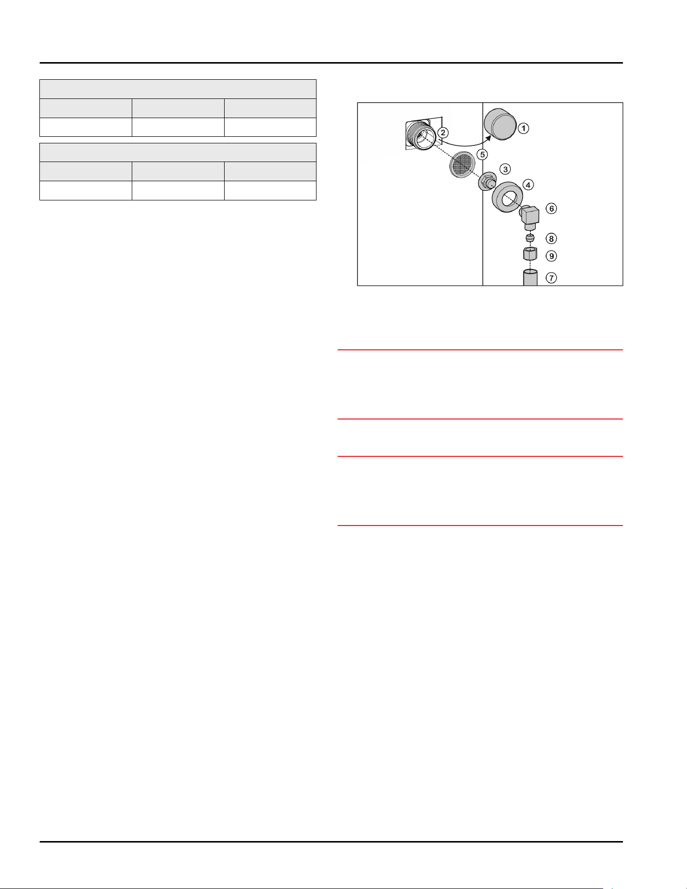
15 Connecting the water supply*
Fig. 50
Connect the coupler to the appliance
u
Remove cap Fig. 50 (1) from solenoid valve Fig. 50 (2).
u
Insert coupler Fig. 50 (3) into union nut Fig. 50 (4).
NOTICE
Improper installation of water filter Fig. 50 (5)!
Damage to the water filter.
u
Insert the filter with the recess pointing towards the
coupler.
u
Insert water filter Fig. 50 (5) with the recess pointing
down towards coupler Fig. 50 (3).
NOTICE
Overtightened union nut!
Damage to the thread.
u
Screw the union nut manually on to the thread until
it is tight and secure.
u
Attach union nut Fig. 50 (4) to solenoid valve Fig. 50 (2)
and tighten.
Water connection at 90°: Connect the water pipe to
the angle piece
u
Screw on angle piece Fig. 50 (6).
u
Connect water pipe Fig. 50 (7) (e.g. copper) to angle
piece Fig. 50 (6) using clamp ring Fig. 50 (8) and nut
Fig. 50 (9).
u
Attach water pipe Fig. 50 (7) to the housing if
possible, using the clip bracket.
Straight water connection: Connect the water pipe to
the coupler
u
Put angle piece Fig. 50 (6) to one side.
u
Connect water pipe Fig. 50 (7) (e.g. copper) to coupler
Fig. 50 (3) using clamp ring Fig. 50 (8) and nut
Fig. 50 (9).
u
Attach water pipe Fig. 50 (7) to the housing if
possible, using the clip bracket.
u
Connect the water pipe to the water valve.
Check the water system
u
Slowly open the water valve of the water supply.
u
Check the entire water system for leaks.
Vent the water system
Connecting the water supply*
* Depending on model and options 23
Loading ...
Loading ...
Loading ...