TIMING LIGHT DIESEL CONVERTER BOX
MODEL NO: TL95
Thank you for purchasing a Sealey product. Manufactured to a high standard, this product will, if used according to these instructions,
and properly maintained, give you years of trouble free performance.
IMPORTANT: PLEASE READ THESE INSTRUCTIONS CAREFULLY. NOTE THE SAFE OPERATIONAL REQUIREMENTS, WARNINGS & CAUTIONS. USE
THE PRODUCT CORRECTLY AND WITH CARE FOR THE PURPOSE FOR WHICH IT IS INTENDED. FAILURE TO DO SO MAY CAUSE DAMAGE AND/OR
PERSONAL INJURY AND WILL INVALIDATE THE WARRANTY. KEEP THESE INSTRUCTIONS SAFE FOR FUTURE USE.
1. SAFETY
▲ DANGER BE AWARE, LEAD-ACID BATTERIES CAN GENERATE EXPLOSIVE GASES DURING CHARGING. CARE SHOULD BE
EXERCISED DURING CONNECTION/DISCONNECTION OF THE CONVERTER BOX AND ASSOCIATED EQUIPMENT TO AVOID/
PREVENT SPARKS.
1.1. PERSONAL PRECAUTIONS
9 Wear safety eye protection and protective clothing and avoid touching eyes while working near a battery.
9 Follow good workshop practice by ensuring jewellery is removed, long hair is tied back and there is no loose clothing.
9 Ensurethereisanotherpersonwithincloserangetocometoyouraidshouldaproblemariseandfollowroutinerstaidrequirements
in the event of any accident or injury.
8 Note: Whenusedinconjunctionwithatiminglight,theashingfromthelightcanmakerotatingcomponentsappearstationary.
8 DO NOT be tempted to touch an apparently stationary component, which is in fact, rotating.
WARNING! Ignition components may contain very high voltages; always refer to manufacturers data for advice.
1.2. GENERAL SAFETY INSTRUCTIONS
WARNING!Ensureadequateventilationoranexhaustgasextractionsystemisused.Alwaysadheretoalllegalrequirements,and
workshopgoodpracticerequirementsinyourworkingenvironment.
9 Ensuretheignitionisswitchedobeforeattachingthepowerclampstothebattery.Ifthebatteryterminalsarecorrodedordirty,clean
them before attaching any clamps.
8 DO NOTcross-connectleadsfromtheconverterboxtothebattery.Ensurepositive(+)(RED)istopositiveandnegative(-)BLACKis
to negative.
8 DO NOTallowinductivepick-up,orleads,tocontactexhaustorotherenginepartsastheheatwillcausedamage.
8 DO NOT pull the cable or clamps from the battery terminals.
8 DO NOTusetheconverterboxindamp,orwetlocations.
2. INTRODUCTION
Usedtodetectthepulsefromthefuelpipesofdieselfuelinjectors.Worksonmostdirectinjectiondieselenginesfittedwith6mm(1/4”)to10mm(3/8”)
externalfuelpipes.Suitableforusewithmosttiminglights, engine analysers and multi-meters that have an inductive pick-up.
3. SPECIFICATION
Model no: ....................................................................... TL95
Input power: ........................................................... 6-30VDC
Trigger point: .............................. 15%ofthehighestpressure
Clamp size: .................................. 6mm(1/4”)to10mm(3/8”)
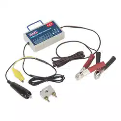
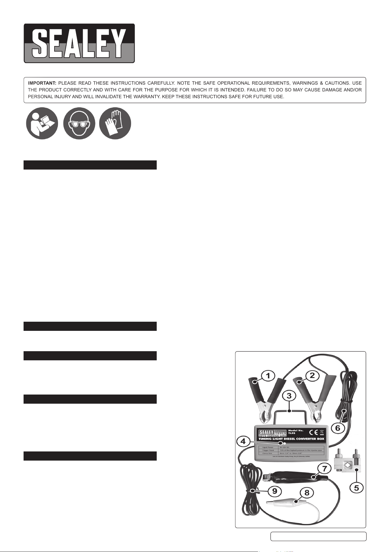
4. CONTENTS
System Component Identification:
1 Blackbatteryclamp(NEG-) 6 PowerLead
2 Redbatteryclamp(POS+) 7 BlackClip(Sensorlead)
3 Pick-uploop 8 YellowClip(Sensorlead)
4 IndicatorLight 9 Sensorlead
5 Piezoclamp(dieselsensor)
5. SET UP & OPERATIONt
5.1. Youmustuseamonitoringdevicesuchasatiminglight,engineanalyser
ormultimeterinconjunctionwiththedieselconverterboxinordertobeable
to read RPM on the device’s display. The most common use for this
information will be for setting a constant engine speed for diesel engine
smoke testing. Remember to set up your monitoring device for the correct
number of cylinders.
5.2. Ensure that the vehicle ignition is off. Locate the fuel pipes connecting the
pump to the fuel injectors. For engine timing purposes the Piezo Clamp
shouldbeattachedtothepipegoingtotheNo.1cylinder.
TL95|Issue:3(1)08/07/20
Original Language Version
© Jack Sealey Limited
Refer to
instruction
manual
Wear eye
protection
Wear
protective
gloves
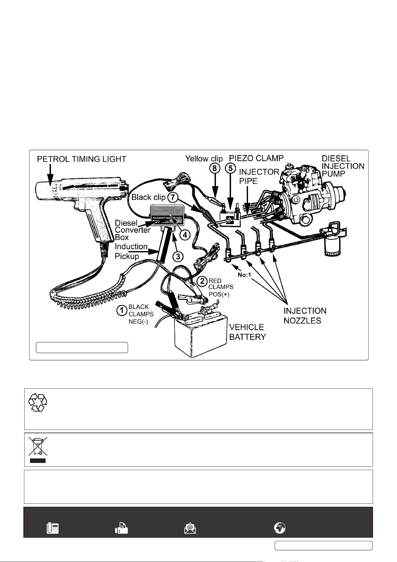
5.3. FixthePiezoClamp(5)ontoastraightsectionoftheInjectorfuelpipefortheNo.1cylinderasclosetothepumpaspossibleinorderto
get the strongest reading. The Piezo Clamp and fuel pipe should be clean and dry.
Make sure that the Piezo Clamp is in full contact with the fuel pipe but DO NOT overtighten as this could cause damage to the sensor
within the clamp.
5.4. TaketheSensorLeadandconnecttheYELLOWclip(8)tooneoftheadjustablefixingsontheclampandtheBLACKclip(7)tothesame
Injector fuel pipe to which the clamp is connected.
WARNING! Ensure that the Black Sensor clip DOES NOT touch any of the Glow Plugs and associated mountings or wiring as this may
cause a short circuit which could disable engine operation and may damage any connected monitoring device.
5.5. TakethePowerLeadandconnecttheREDclamp(2)tothepositivesideofthevehiclebatteryandtheBLACKclamp(1)tothenegative
of the battery.
Note: The monitoring device used i.e. A Timing Light, Engine Analyzer or Digital Multimeter may also be powered from the vehicle’s
battery.
5.6. Attachtheinductivepickupfromyourchosenmonitoringdevicee.g.atiminglight,ontothePickupLoop(3)ontheconverterbox.Ifthe
timing light inductive pickup has an arrow mark, ensure that the mark is face up when attached to the Pickup Loop.
5.7. Start the engine and allow it to reach operating temperature, then read the results from the timing light. The Indicator Light on the
converterbox(4)shouldflashconsistently.Iftheindicatorlightdoesnotflash,checkalltheconnectionsorrelocatethePiezo
Clamp to another section of the fuel pipe. Note: Low vehicle battery, defective Injector Pump, or lack of fuel may prevent the Indicator
Light from flashing.
OPERATION DIAGRAM
Original Language Version
© Jack Sealey Limited
TL95|Issue:3(1)08/07/20
Sealey Group, Kempson Way, Suffolk Business Park, Bury St Edmunds, Suffolk. IP32 7AR
01284 757500 01284 703534 sales@sealey.co.uk www.sealey.co.uk
ENVIRONMENT PROTECTION
Recycle unwanted materials instead of disposing of them as waste. All tools, accessories and packaging should be sorted, taken to
a recycling centre and disposed of in a manner which is compatible with the environment. When the product becomes completely
unserviceableandrequiresdisposal,drainanyfluids(ifapplicable)intoapprovedcontainersanddisposeoftheproductandfluids
according to local regulations.
WEEE REGULATIONS
DisposeofthisproductattheendofitsworkinglifeincompliancewiththeEUDirectiveonWasteElectricalandElectronicEquipment
(WEEE).Whentheproductisnolongerrequired,itmustbedisposedofinanenvironmentallyprotectiveway.Contactyourlocalsolid
waste authority for recycling information.
Note: It is our policy to continually improve products and as such we reserve the right to alter data, specifications and component parts without prior
notice.
Important: No Liability is accepted for incorrect use of this product.
Warranty:Guaranteeis12monthsfrompurchasedate,proofofwhichisrequiredforanyclaim.
