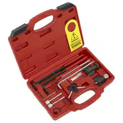
DIESEL ENGINE TIMING TOOL KIT - FOR VAG 1.4D,
1.6D, 2.0D - BELT DRIVE
MODEL NO: VS5170
Thank you for purchasing a Sealey product. Manufactured to a high standard, this product will, if used according to these
instructions, and properly maintained, give you years of trouble free performance.
IMPORTANT: PLEASE READ THESE INSTRUCTIONS CAREFULLY. NOTE THE SAFE OPERATIONAL REQUIREMENTS, WARNINGS & CAUTIONS. USE
THE PRODUCT CORRECTLY AND WITH CARE FOR THE PURPOSE FOR WHICH IT IS INTENDED. FAILURE TO DO SO MAY CAUSE DAMAGE AND/OR
PERSONAL INJURY AND WILL INVALIDATE THE WARRANTY. KEEP THESE INSTRUCTIONS SAFE FOR FUTURE USE.
1. SAFETY
WARNING! Wear approved eye protection. Wear appropriate Personal Protective Equipment. A full range of Personal Protective
Equipment is available from your Sealey stockist.
WARNING! Ensure that Health & Safety, Local Authority Regulations and general workshop practice Regulations are adhered to
when using tools.
8 DO NOT use tools if damaged.
9 Maintain tools to ensure that they are in an adequate condition for safe use and optimum performance.
9 Ensure that a vehicle that has been raised by a jack is adequately supported. Use axle stands.
9 Wear suitable clothing to avoid snagging. DO NOT wear jewellery. Tie back long hair.
9 Account for all tools, parts and components being used. DO NOT leave these in or near the engine. Return tools to suitable
storage after use.
▲ IMPORTANT! These Instructions are provided as a guide only. Always refer to the vehicle manufactures’ service instructions or a
proprietary manual to establish the correct procedure and data.
WARNING! The warnings, cautions and instructions in this manual cannot cover all possible conditions and situations. The
Operator / user must apply caution and common sense (good practical sense).
9 When timing an engine, always prevent the engine from being turned over. Use a notice and/or inhibit the engine.
WARNING! Incorrect or out of phase camshaft timing can result in contact between the valve head and the piston crown. This will
cause damage to the engine.
2. INTRODUCTION
Covers the new generation 3 and 4-cylinder common rail diesel engines. Includes the tools required for setting the camshaft drive
gears within the cylinder head.
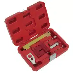
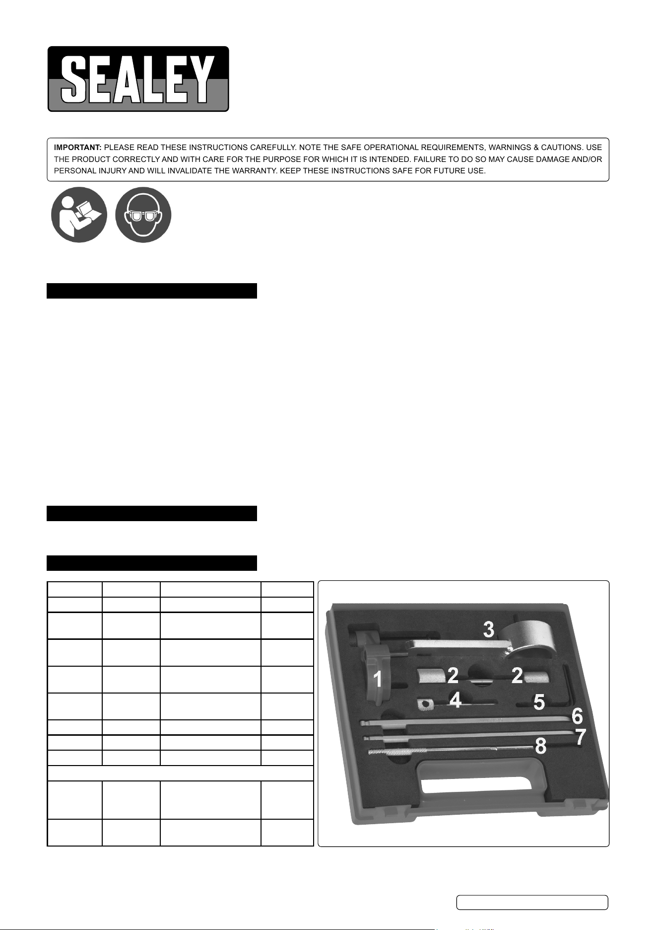
3. CONTENTS
Item Part no. Description OE Tool
1 VS5170.01 Crankshaft locking tool T10490
2 VS5170.02 Camshaft/H.P. pump
locking pin
T10492
3 VS5170.03 Camshaft/H.P. pump
sprocket holding tool
T10051
4 VS5170.04 Camshaft/H.P.pump
locking pin
VAG3359
5 VS5170.05 Auxillary belt tensioner
locking pin
T10060A
6 VS5170.06 Tensioner adjuster T10409
7 VS5170.07 Tensioner adjuster T10264
8 VS5170.08 Tensioner locking tool T10265
Associated Tools
VSE5852 Service position front
end support guide -
VAG
VS783 Universal pulley & fan
clutch holder set
Wear eye
protection
Refer to
instruction
manual
Original Language Version© Jack Sealey Limited
VS5170 Issue 8 (3) 20/02/24
4. APPLICATIONS
1.4/1.6/2.0TDi Common Rail (EA288) Diesel engines
Make: Model:
Audi A1 (15-18), A1 Sportback (15-18), A3 (09-23), A3 Cabriolet (14-17), A3 (20-24), A3 Sportback (20-24), A4 (13-21),
A4 Quattro (13-21), A4 Allroad (13-19), A5 (13-17), A5 Coupe (13-21), A5 Cabriolet (13-21), A5 Sportback (13-22), A6 (13-23),
A6 Quattro (15-23), Q3 (11-24), Q3 Sportback (20-24), Q5 (13-22)
Seat Alhambra (10-18), Ibiza (15-17), Leon (12-17), Leon ST (13-18), Tarraco (20-24), Toledo (15-18).
Skoda Fabia III (14-18), Kodiaq (20-24), Octavia (13-15), Octavia III (15-18), Rapid (15-17), Superb III (15-24), Yeti (09-17),
Yeti Outdoor (13-17).
Volkswagen
Arteon (20-24), CC (12-17), Caddy (98-21), Golf VI (09-13), Golf VII (12-17), Golf VII Estate (13-17), Golf VII SV (14-17)
Sportsvan (14-17), Golf VIII (20-24), Passat (11-23), Passat CC (10-12), Polo (14-18), Scirocco (14-18), Sharan (11-17),
Tiguan (10-24), Tiguan Allspace (20-24), Q3 (20-23), Q3 Sportback (20-23), Q5 (19-20) Transporter T6 (15-21).
Engine codes:
1.4 D TDi: CUSA, CUSB, CUTA
1.6 D TDi CLHA, CLHB, CRKA, CRKB, CXMA, CXXA, CXXB
2.0 D TDi Diesel Engine:I BFSC, CFFA, CKFB, CKFC, CNHA, CNHC, CRBC, CRBD, CRFA, CRFC, CRKB, CRLB, CRLC, CRMB,
CRVA, CRVC, CSUA, CSUD, CUNA, CUPA, CUVA, CUVC, CUWA, CXGA, CXGB, CXGC, CXGD, DEFZ, DETB, DEZB, DEZD,
DEZE, DEZF, DETA, DEUA, DEUB, DEUC, DFBA, DFCA, DFLA, DFSB, DFSD, DFSE, DSRA, DSRB, DTSA, DTSB.
5. INSTRUCTIONS
5.1. Engine timing check
5.1.1. Remove the engine top cover.
5.1.2. Detach the coolant return pipe from the expansion tank.
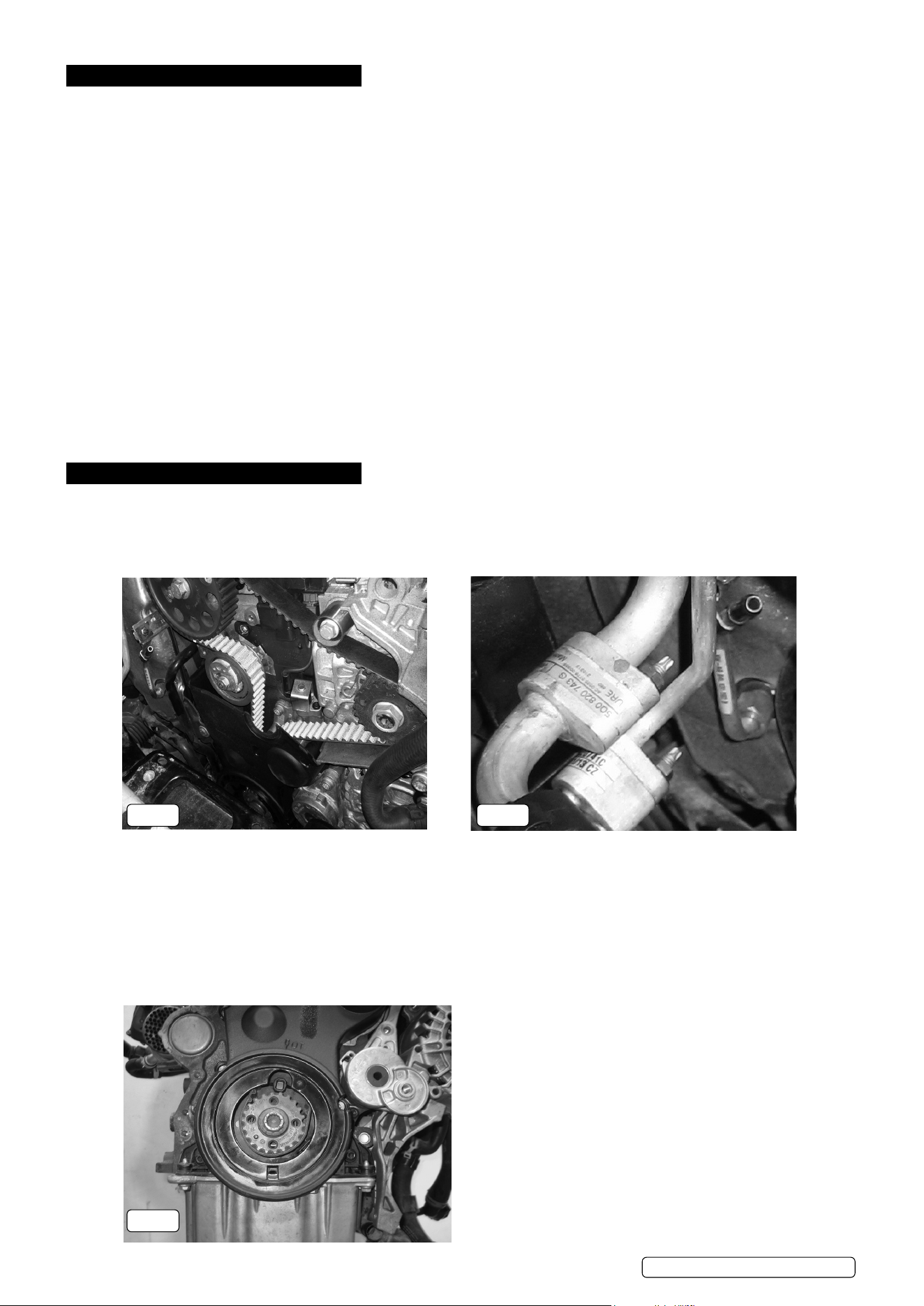
5.1.3. Remove the low pressure fuel feed pipes and coolant pipes to gain access to the toothed belt upper cover.
5.1.4. IMPORTANT: Cap the ends of all open pipes to prevent ingress of dirt and foreign objects.
Fig.1
5.1.5. Remove the toothed belt upper cover.
5.1.6. Raise the vehicle and remove the wheel and inner body shield.
Fig.2
5.1.7. Rotate the auxiliary belt tensioner in an anti-clockwise direction to release tension from the belt, retain the tensioner in position
using VS5170.05 tensioner locking pin.
5.1.8. Remove the auxiliary belt from the engine.
Note: If the auxiliary belt is to be retted, mark the direction of rotation on the belt before removing it from the engine. Retting a
used auxiliary belt in the opposite direction of rotation may cause premature failure of the belt.
LB,
Fig.3
Original Language Version© Jack Sealey Limited
Fig.1 Fig.2
VS5170 Issue 8 (3) 20/02/24
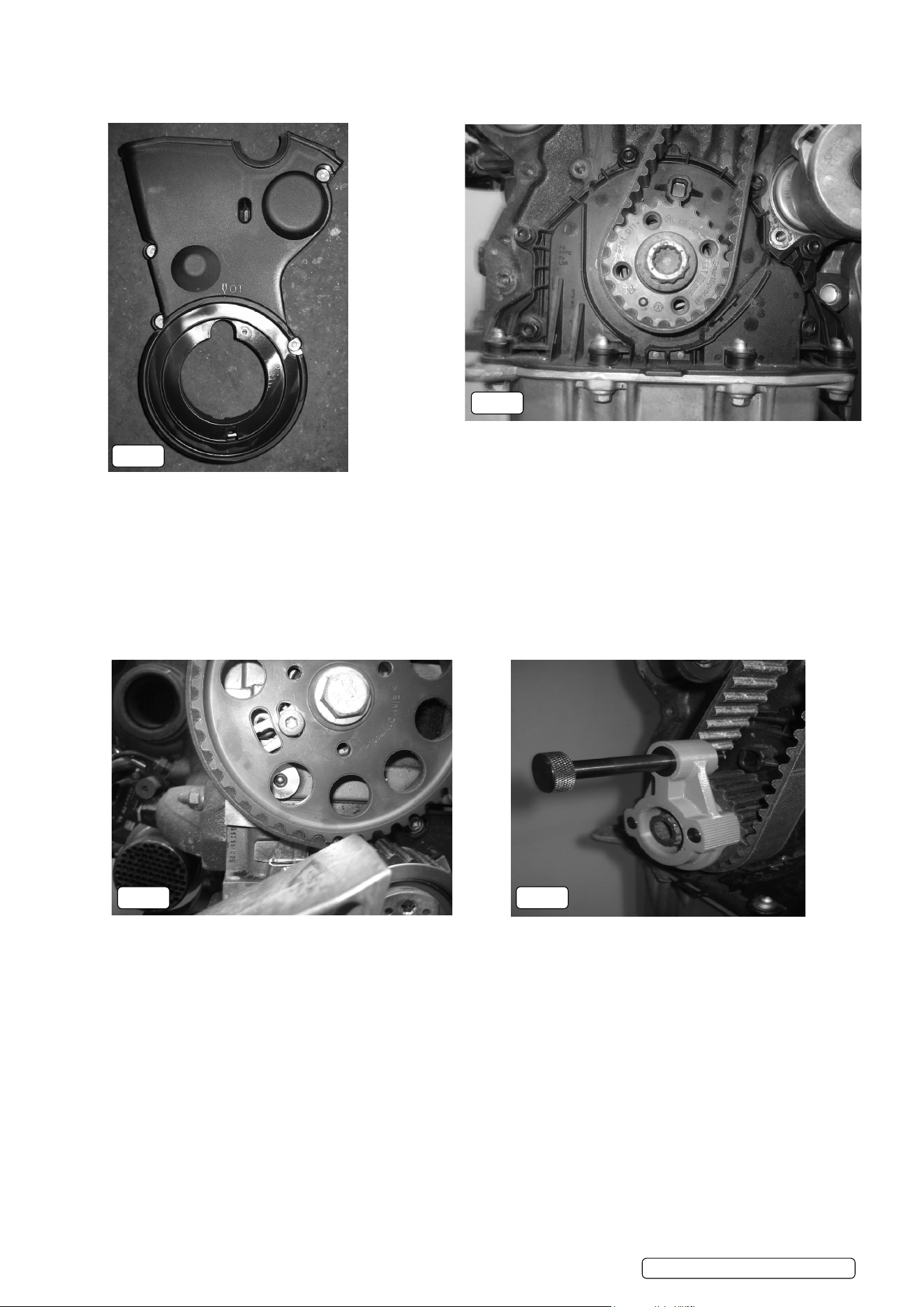
Fig.3
5.1.9. Using a 19mm bi-hex socket tted to the crankshaft central bolt as a counter hold, remove the 4 crankshaft pulley retaining bolts and
the crankshaft pulley from the engine.
5.1.10. Release the 4 retaining screws and remove the toothed belt lower cover.
Fig.4
5.1.11. To remove the lower cover on some early engines (MY:2012-2013) an 8mm hole must be drilled through the cover 10mm above the
lower retaining clip, just below the crankshaft sprocket. It is then necessary to use a small at screwdriver to break off the assembly
guide lug that is moulded on to the back of the lower cover. The lower cover has been modied on later engines, it is no longer
necessary to drill a hole to remove the cover as the locking tab can be accessed through the moulded aperture in the cover.
IMPORTANT: If drilling an access hole in the lower cover, care must be taken not to damage the toothed belt situated behind the
cover. If the toothed belt, the crankshaft sprocket or the crankshaft sealing ange are damaged they must be replaced. DO NOT ret a
damaged toothed belt.
Fig.5
5.1.12. Rotate the crankshaft in the normal direction of engine rotation until the guide peg of the crankshaft sprocket is positioned at
approximately 7 o’clock relative to the central bolt.
Fig.6
5.1.13. Check that the location fork of the camshaft hub is positioned at approximately 7 o’clock relative to the camshaft central bolt (just
before it reaches the location hole in the cylinder head). If it is approximately 180° out of position, remove VS5170.01, rotate
the crankshaft 1 full turn and check the positions again.
Fig.7
5.1.14. Locate VS5170.01 Crankshaft Locking Tool onto the crankshaft sprocket, ensuring that the sprocket guide peg is located in the recess
on the face of VS5170.01.
Fig.5
Fig.4
Fig.6
Fig.7
Original Language Version© Jack Sealey Limited
VS5170 Issue 8 (3) 20/02/24
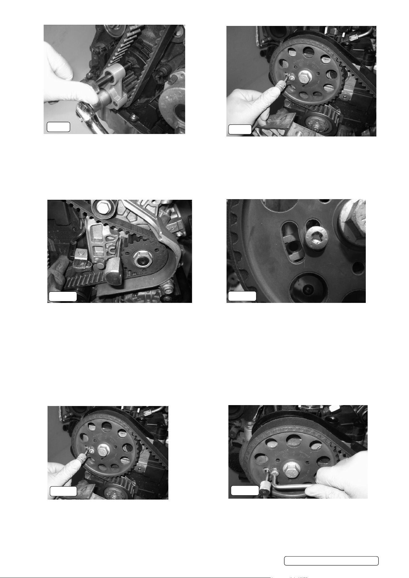
Fig.8
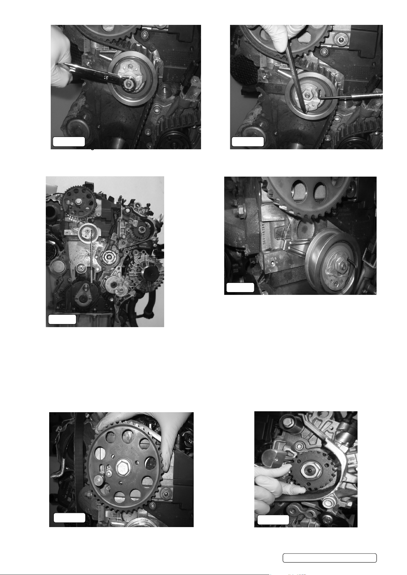
5.1.15. Continue to rotate the crankshaft in the normal direction of engine rotation until the locking pin of VS5170.01 crankshaft locking tool is
aligned with the moulded location pocket in the crankshaft seal housing.
5.1.16. Ensure that the body of VS5170.01 is fully located on the crankshaft sprocket, then slide the locking pin into the pocket of the
crankshaft seal housing.
Fig.9
5.1.17. Install VS5170.04 camshaft locking pin through the location fork of the camshaft sprocket and into the location hole of the cylinder
head. If it is not possible to install VS5170.04 into the cylinder head, the engine timing will require adjustment.
Fig.10
5.1.18. Check that the location hub fork of the high pressure fuel pump sprocket is positioned over the location hole of the engine. Install
VS5170.02 H.P. Pump locking pin through the location hub fork of the H.P. pump sprocket and into the location hole of the engine.
Note: It may not be possible to t the H.P. Pump locking pin if the hub fork is slightly out of alignment. Misalignment of 1-2mm at
the H.P. Pump hub is not detrimental to the operation of the engine and is acceptable.
5.1.19. If it is not possible to correctly install VS5170.01 Crankshaft Locking tool and VS5170.04 camshaft setting pin, the engine timing
will require adjustment.
5.2. Engine Timing - Adjustment
5.2.1. Remove all timing tools from the engine.
Note: If the toothed belt or toothed belt tensioner are to be replaced, the engine mount bracket must be removed. Ensure that the
engine is safely supported before removing the engine mount bracket.
Fig.11
5.2.2. Rotate the crankshaft in the normal direction of engine rotation until the camshaft hub fork is aligned with the location hole of the
cylinder head.
Fig.12
5.2.3. Install VS5170.04 camshaft locking pin through the location fork of the camshaft sprocket and into the location hole in the cylinder
head.
Fig.13
5.2.4. Release the hub fork screw by 1/2 a turn. DO NOT remove the hub locking screw.
Fig.8
Fig.9
Fig.13
Fig.12
Fig.10
Fig.11
VS5170 Issue 8 (3) 20/02/24
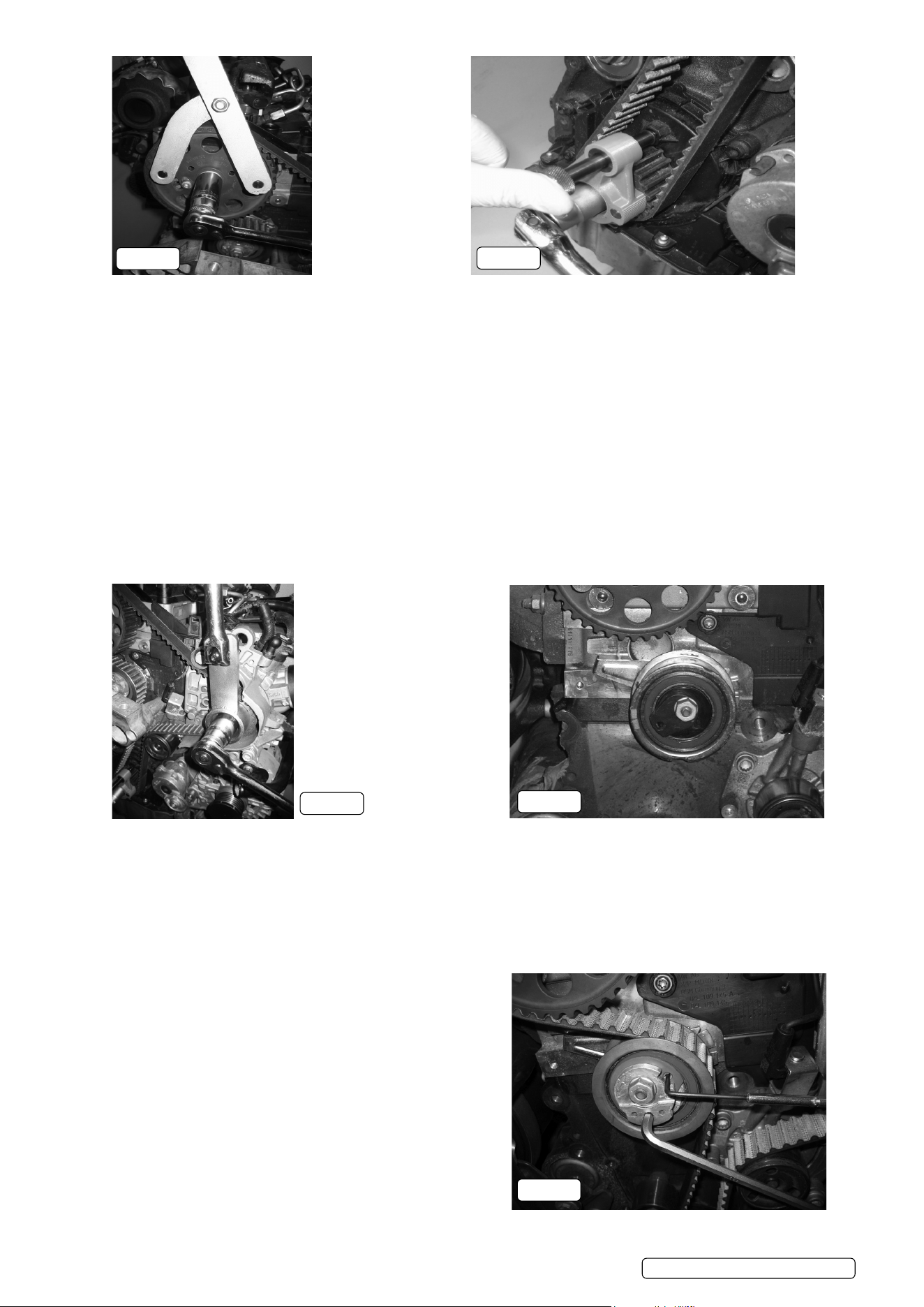
Fig.14
5.2.5. Remove VS5170.04 Camshaft Locking Pin.
5.2.6. Using a suitable counter-hold tool, such as VS783 Camshaft Sprocket Holding Tool, release the central bolt of the camshaft
sprocket by ¼ turn.
5.2.7. Ret VS5170.04 Camshaft Locking Pin through the location fork of the camshaft sprocket and into the location hole in the cylinder
head. Release the central bolt of the camshaft sprocket by another ¼ turn so that the sprocket is free to rotate on the hub of the
camshaft.
5.2.8. DO NOT remove the central bolt of the camshaft sprocket.
5.2.9. Locate VS5170.01 Crankshaft Locking Tool onto the crankshaft sprocket, ensuring that the sprocket guide peg is located in the recess
on the face of VS5170.01, see g.8.
Fig.15
5.2.10. Rotate the crankshaft until the locking pin of VS5170.01 crankshaft locking tool is aligned with the moulded location pocket in the
crankshaft seal housing.
5.2.11. Ensure that the body of VS5170.01 is fully located on the crankshaft sprocket, then slide the locking pin into the pocket of the
crankshaft seal housing.
IMPORTANT: Engine setting/locking tools MUST NOT be used to counter-hold the camshaft or high pressure pump when releasing or
tightening the sprocket nuts/bolts.
Fig.16
5.2.12. Using VS5170.03 Sprocket Holding Tool to counter-hold the high pressure fuel pump sprocket, release the pump sprocket retaining nut
by ¼ turn.
5.2.13. Install VS5170.02 H.P. Pump Locking Pin through the location fork of the high pressure fuel pump and into the location hole in the
cylinder head. Using VS5170.03 Sprocket Holding Tool to counter-hold the high pressure fuel pump sprocket, release the pump
sprocket retaining nut by a further ¼ turn so that the sprocket is free to rotate on the hub of the high pressure pump.
Fig.17
5.2.14. There are two types of tensioner tted to this range of engines. Each type requires different tooling when releasing or applying tension
to the belt. Tools for both tensioners are included within the kit.
Fig.18
5.2.15. Type 1: Use VS5170.06 Tensioner Adjuster to release &
apply tension.
5.2.16. Type 2: Use VS5170.07 Tensioner Adjuster to release &
apply tension, use VS5170.08 Tensioner Locking Pin to retain
the tensioner hub.
Fig.14
Fig.17
Fig.18
Fig.15
Original Language Version© Jack Sealey Limited
Fig.16
VS5170 Issue 8 (3) 20/02/24
Figs 19A & 19B
5.2.17. Release the toothed belt tensioner retaining nut.
5.2.18. Using a suitable tensioner adjuster, rotate the tensioner in an anti-clockwise direction to release tension from the belt. If a type 2
tensioner is tted, install VS5170.08 Tensioner Locking Pin through the aperture in the front of the tensioner hub.
Fig.20
5.2.19. Remove the toothed belt from the camshaft sprocket and H.P pump sprocket.
5.2.20. Replacement of the toothed belt is recommended.
Note: If the toothed belt is to be retted, mark the direction of rotation on the belt before removal.
Fig.21
5.2.21. Replace the toothed belt idler pulleys.
5.2.22. Replace the toothed belt tensioner and retaining nut.
5.2.23. Ensure that the metal location tab of the toothed belt tensioner is located in the aperture of the engine block. Retain the tensioner in
position by tightening the retaining nut nger tight only at this stage.
5.2.24. Ensure that the crankshaft sprocket, the camshaft hub and the high pressure fuel pump hub are positioned and retained
by the engine setting/locking tools, see g.20.
Figs 22A & B
5.2.25. Rotate the camshaft sprocket and the high pressure fuel pump sprocket in a clockwise direction until they reach their limit of travel on
the hubs.
Fig.20
Fig.22B
Fig.22A
Fig.19B
Original Language Version© Jack Sealey Limited
Fig.19A
VS5170 Issue 8 (3) 20/02/24
Fig.21
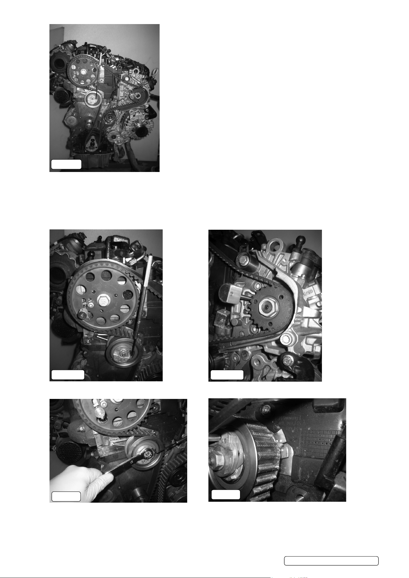
Fig.23
5.2.26. Starting at the crankshaft sprocket and working in a clockwise direction, t the toothed belt onto the engine.
5.2.27. Ensuring that the teeth of the belt remain fully located in the teeth of the crankshaft sprocket, t the belt to the idler pulley and belt
tensioner pulley.
5.2.28. Maintaining the position of the camshaft and high pressure pump sprockets, t the toothed belt on to the camshaft sprocket, the 2nd
idler pulley and the high pressure fuel pump sprocket.
5.2.29. Finally t the toothed belt over coolant pump pulley.
Figs. 24A & 24B
5.2.30. Check that the camshaft sprocket and H.P. fuel pump sprockets are on or near their clockwise limit of rotation.
Fig.25
5.2.31. Release the tensioner retaining nut.
5.2.32. Ensure that the location tab of the toothed belt tensioner is located in the aperture of the engine block.
Fig.26
5.2.33. Remove VS5170.08 Tensioner Locking Pin.
5.2.34. Using VS5170.07 or VS5170.06 Tensioner Adjuster, rotate the eccentric hub of the tensioner pulley in a clockwise direction until the
tension indicator arrow is aligned with the slot in the tensioner body.
Fig.23
Fig.24B
Fig.24A
Fig.26
Fig.25
Original Language Version© Jack Sealey Limited
VS5170 Issue 8 (3) 20/02/24
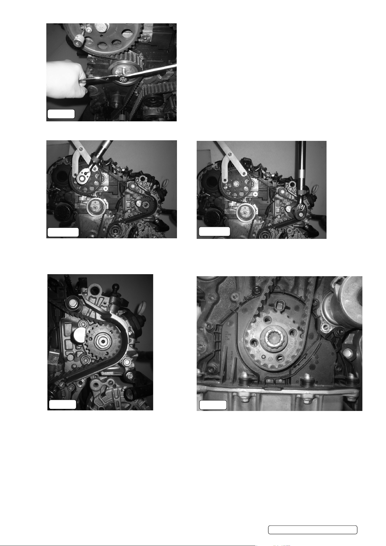
Fig.27
5.2.35. While maintaining the correct position of the tensioner, tighten the retaining nut to 20Nm+45°.
Figs 28A & 28B
5.2.36. Using a counter-hold tool, such as VS783 Camshaft Sprocket Holding Tool, tighten the central bolt of the camshaft sprocket to
10Nm and the central nut of the high pressure fuel pump sprocket to 10Nm.
IMPORTANT: Engine setting/locking tools MUST NOT be used to counter-hold the camshaft or high pressure pump when releasing or
tightening the sprocket nuts/bolts.
Fig.29
5.2.37. Ensure that the mark on the H.P. Pump sprocket is in the correct position. The top mark must be positioned above the shaft of the
locking pin. If the top mark is aligned with the locking pin, the timing belt must be retted with the sprocket in the correct position.
5.2.38. Remove all engine setting/locking tools.
Fig.30
5.2.39. Rotate the crankshaft 2 full turns in the normal direction of engine rotation until the guide peg of the crankshaft sprocket is positioned
at approximately 7 o’clock relative to the central bolt.
Fig.27
Fig.28A
Fig.29
Fig.30
Original Language Version© Jack Sealey Limited
Fig.28B
VS5170 Issue 8 (3) 20/02/24
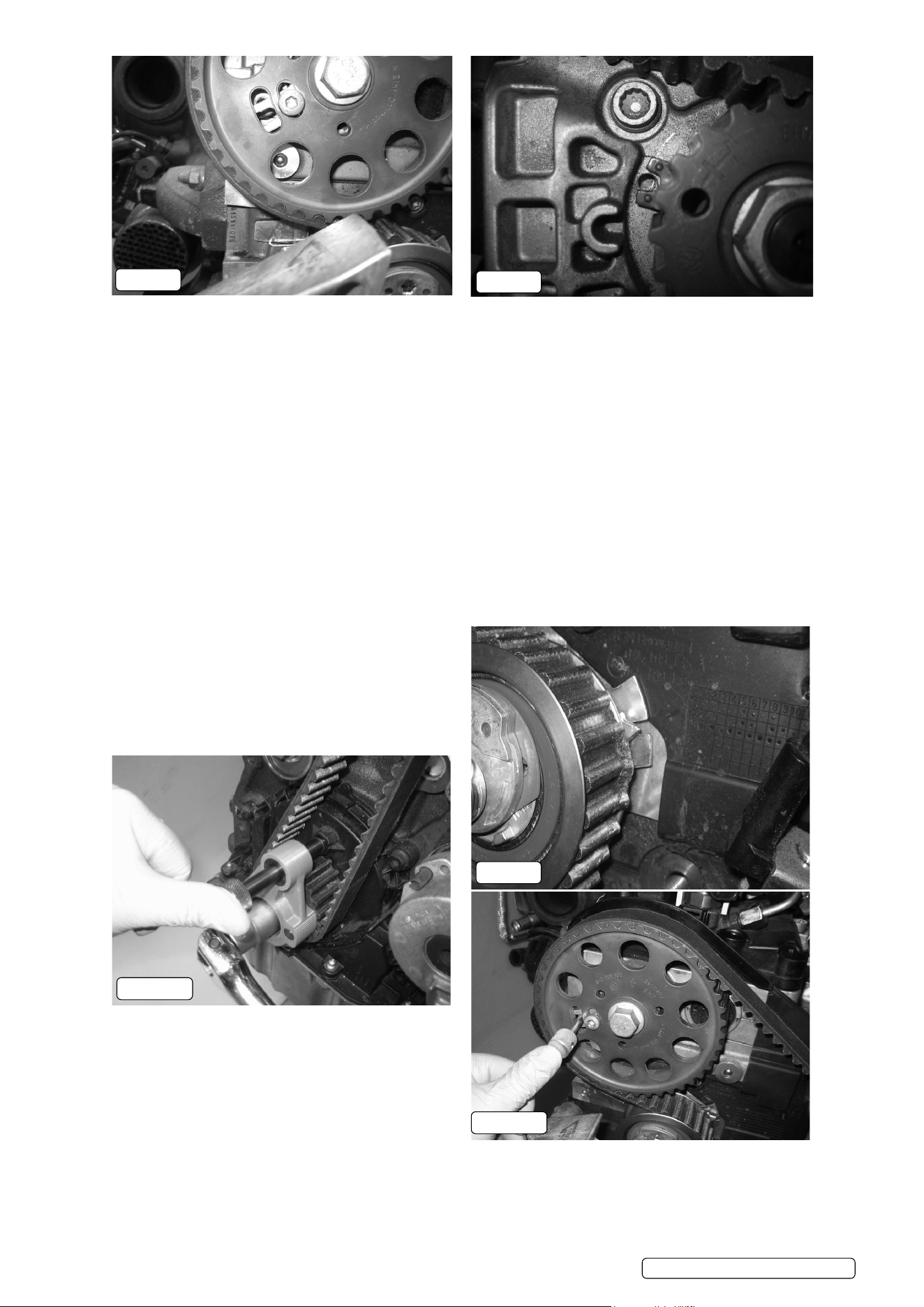
Fig.31
5.2.40. Check that the location fork of the camshaft hub is positioned at approximately 7 o’clock relative to the camshaft central bolt (just
before it reaches the location hole in the cylinder head).
WARNING: Only rotate the engine in the normal direction of rotation. If the location fork is positioned after the location hole in the
cylinder head, rotate the crankshaft a further 2 full turns and check the position again. DO NOT rotate the crankshaft in the opposite
direction to normal engine rotation.
5.2.41. Locate VS5170.01 Crankshaft Locking Tool onto the crankshaft sprocket, ensuring that the sprocket guide peg is located in the recess
on the face of VS5170.01, see g.7.
5.2.42. Slowly rotate the crankshaft in the normal direction of engine rotation until the locking pin of VS5170.01 crankshaft locking tool is
aligned with the moulded location pocket in the crankshaft seal housing.
5.2.43. Ensure that the body of VS5170.01 is fully located on the crankshaft sprocket, then slide the locking pin into the location pocket of the
crankshaft seal housing, see g.8.
5.2.44. Install VS5170.04 camshaft locking pin through the location fork of the camshaft sprocket and into the location hole of the cylinder
head. If it is not possible to install VS5170.04 into the cylinder head, the engine timing will require further adjustment, see g.10.
Fig.32
5.2.45. Check that the location hub fork of the high pressure fuel pump sprocket is positioned over the location hole of the engine. Install
VS5170.02 H.P. Pump locking pin through the location hub fork of the H.P. pump sprocket and into the location hole of the engine.
Note: After rotation of the crankshaft it may not be possible to t the H.P. Pump locking pin as the hub fork can be slightly out of
alignment. Misalignment of 1mm at the H.P. Pump hub will prevent the locking pin from entering the location hole, but is not
detrimental to the operation of the engine and is a permissible error.
Fig.33
5.2.46. Ensure that the indicator arrow of the toothed belt tensioner
is aligned with the slot in the tensioner body.
Note: Belt tension may settle during initial rotation of the
crankshaft. The tension indicator may not return to exactly
the same position. Slight differences in tension indicator
position are normal and do not affect the operation of the
tensioner or the toothed belt.
Fig.34 A & 34B
5.2.47. If it is not possible to correctly install VS5170.01 Crankshaft
Locking Tool and VS5170.04 Camshaft Setting Pin, or the
location fork of the high pressure pump is excessively.
5.2.48. Misaligned, the engine timing will require adjustment.
5.2.49. To fully reset or adjust the timing, refer to the section 5.2.
Fig.32
Fig.31
Fig.34A
Fig.34B
Fig.33
Original Language Version© Jack Sealey Limited
VS5170 Issue 8 (3) 20/02/24
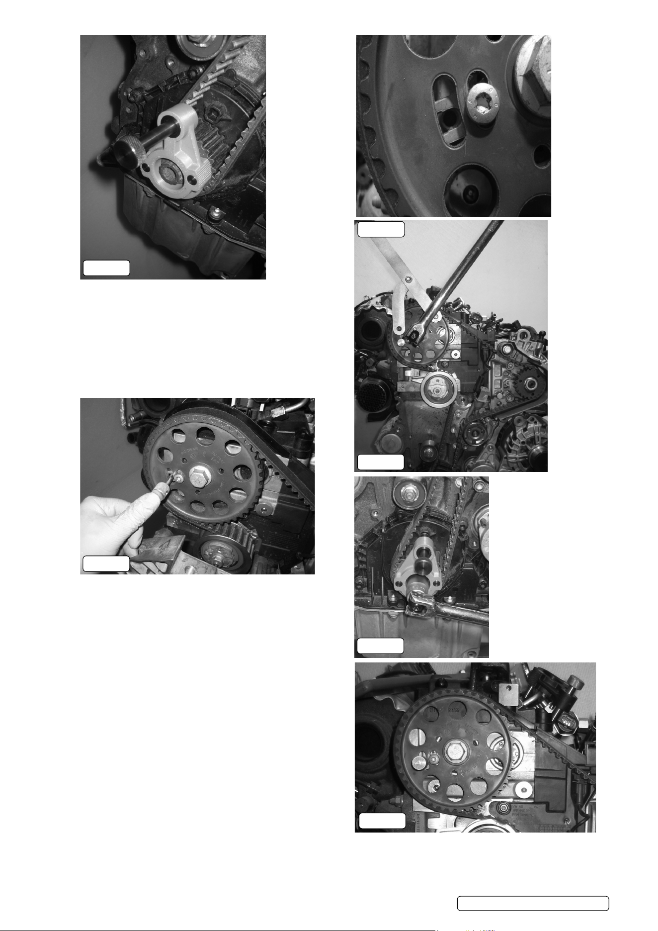
Fig.35
5.2.50. Rotate the crankshaft backwards until the location pin of
VS5170.01 Crankshaft Locking Tool is positioned approximately
10-20° before the moulded location pocket in the crankshaft seal
housing.
Fig.36
5.2.51. Rotate the crankshaft in the normal direction of rotation until
the location fork of the camshaft sprocket is aligned with the
location hole in the cylinder head.
Fig.37
5.2.52. Install VS5170.04 camshaft locking pin through the location
fork of the camshaft sprocket and into the location hole of the
cylinder head.
Fig.38
5.2.53. Using a suitable counter-hold tool, such as VS783 Camshaft
Sprocket Holding Tool, release the central bolt of the camshaft
sprocket so that the sprocket is free to rotate on the hub of the
camshaft. Do not remove the central bolt of the camshaft
sprocket.
Fig.39
5.2.54. Slowly rotate the crankshaft until the locking pin of VS5170.01
crankshaft locking tool is aligned with the moulded location
pocket in the crankshaft seal housing.
5.2.55. Ensure that the body of VS5170.01 is fully located on the
crankshaft sprocket, then slide the locking pin into the location
pocket of the crankshaft seal housing.
Note: If the location pin of VS5170.01 is positioned after the
location pocket of the seal housing rotate the crankshaft backwards
until the locking pin is positioned before the location pocket, then
rotate it in the normal direction of rotation to achieve the correct
position.
Fig.40
5.2.56. Ensure that the screw of the camshaft hub fork is positioned at the lower end of the adjustment slot and that the hub fork of high
pressure fuel pump is positioned correctly.
Fig.35
Fig.37
Fig.38
Fig.39
Fig.36
Fig.40
Original Language Version© Jack Sealey Limited
VS5170 Issue 8 (3) 20/02/24
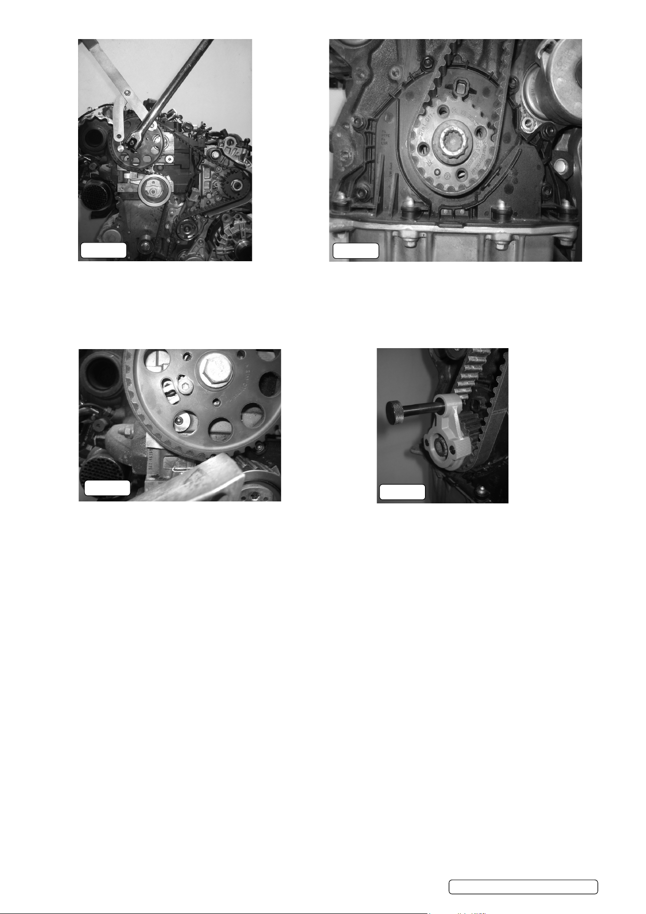
Fig.41
5.2.57. Using a suitable counter-hold tool, such as VS783 Camshaft Sprocket Holding Tool, tighten the central bolt of the camshaft sprocket
to 20Nm.
5.2.58. Remove all setting/locking tools from the engine.
Fig.42
5.2.59. Rotate the crankshaft 2 full turns in the normal direction of engine rotation until the guide peg of the crankshaft sprocket is positioned
at approximately 7 o’clock relative to the central bolt.
Fig.43
5.2.60. Check that the location fork of the camshaft hub is positioned at approximately 7 o’clock relative to the camshaft central bolt (just
before it reaches the location hole in the cylinder head). If it is approximately 180 out of position, rotate the crankshaft 1 full turn and
check the positions again.
Fig.44
5.2.61. Locate VS5170.01 Crankshaft Locking Tool onto the crankshaft sprocket, ensuring that the sprocket guide peg is located in the recess
on the face of VS5170.01.
5.2.62. Continue to rotate the crankshaft in the normal direction of engine rotation until the locking pin of VS5170.01 crankshaft locking tool is
aligned with the moulded location pocket in the crankshaft seal housing.
5.2.63. Ensure that the body of VS5170.01 is fully located on the crankshaft sprocket, then slide the locking pin into the pocket of the
crankshaft seal housing, see g.34A.
5.2.64. Install VS5170.04 camshaft locking pin through the location fork of the camshaft sprocket and into the location hole of the cylinder
head, see g.34B.
5.2.65. If it is not possible to correctly install VS5170.01 Crankshaft Locking Tool and VS5170.04 Camshaft Setting Pin, or the location fork
of the high pressure pump is excessively misaligned, the engine timing will need to be reset. Refer to section 5.2 Engine Timing –
Adjustment.
Fig.41
Fig.42
Fig.44
Fig.43
Original Language Version© Jack Sealey Limited
VS5170 Issue 8 (3) 20/02/24

Fig.45
Remove all engine setting/locking tools.
5.2.66. Using a suitable counter-hold tool, such as VS783 Camshaft Sprocket Holding Tool, tighten the central bolt of the camshaft sprocket
to its nal torque setting of 100Nm
Fig.46
5.2.67. Using VS5170.03 Sprocket Holding Tool as a counter-hold, tighten the central nut of the high pressure fuel pump sprocket to its nal
torque setting of 95Nm.
IMPORTANT: Engine setting/locking tools MUST NOT be used to counter-hold the camshaft or high pressure pump when releasing or
tightening the sprocket nuts/bolts.
Fig.47
5.2.68. Tighten the camshaft hub fork screw to its nal torque setting of 9Nm.
5.2.69. Repeat the timing check procedure.
5.2.70. Ret the engine components in the reverse order of removal.
5.3. Camshaft Adjustment Control Valve - 1.6/2.0TDi
A number of 1.6L and 2.0L 4 cylinder engines are equipped with a hydraulic valve adjustment unit tted to the rear of the inlet
camshaft. When the camshaft adjuster control valve is removed from the inlet camshaft there is no direct connection between the inlet
and exhaust camshaft.
Before removing the camshaft adjuster control valve, the inlet camshaft must be locked in position using VS5170.02 camshaft locking
pin tted through the aperture in the camshaft cover.
Fig.47
Original Language Version© Jack Sealey Limited
Fig.45
Fig.46
VS5170 Issue 8 (3) 20/02/24

Fig.48A
Figs.48A & 48B
5.3.1. Lock the engine in the correct timing position using VS5170.01 Crankshaft locking tool and VS5170.04 Camshaft timing
pin as described in the section 5.1. “Engine timing – Check”.
Fig.49
5.3.2. Remove the blanking plug from the camshaft cover.
5.3.3. Insert VS5170.02 camshaft locking pin through the aperture in the camshaft cover until the pin is fully located in the camshaft. When
VS5170.02 is correctly tted there will be a gap of 1mm between the head of VS5170.02 camshaft locking pin and the plastic camshaft
cover.
Fig.50
5.3.4. If the plastic camshaft cover is not tted to the engine, the groove on the shaft of the pin should be used as a reference to ensure that
the pin is correctly tted. The groove of VS5170.02 camshaft locking pin must be aligned with the aluminium camshaft housing.
Fig.51
5.3.5. Release the central bolt of the valve adjustment unit.
IMPORTANT: DO NOT remove VS5170.02 pin from the inlet camshaft while the adjustment unit control valve is not tted.
Unintentional camshaft rotation may result in damage to the valves or the piston crown.
Fig.52
5.3.6. Remove the adjustment unit from the camshaft as required.
IMPORTANT: A diamond coated friction washer is located between the end of the inlet camshaft and the valve adjustment unit. This
washer MUST be retted when the unit is reassembled.
Fig.48B
Fig.50
Fig.52
Fig.51
Fig.49
Original Language Version© Jack Sealey Limited
VS5170 Issue 8 (3) 20/02/24
Fig.53 Fig.54
Fig.53
5.3.7. Reassembly of the camshaft adjustment unit is carried out in the reverse order or removal.
5.3.8. Install a new camshaft adjustment control valve, tightening the camshaft adjustment control valve to its nal torque setting of 50Nm.
5.3.9. Remove all timing tools.
Fig.54
5.3.10. Rotate the crankshaft two full turns in the normal direction of engine rotation.
5.3.11. Check the engine timing as described in section 5.1 “Engine Timing – Check”.
5.3.12. Insert VS5170.02 camshaft locking pin through the aperture in the camshaft cover until the pin is fully located in the camshaft to check
the positioning of the inlet camshaft.
5.3.13. Reassemble the vehicle in the reverse order of removal.
5.4. Balance shaft unit – 1.4TDi 3 Cylinder engine
5.4.1. 1.4L 3 cylinder engines are equipped with balance shafts that are incorporated as part of the oil pump unit. The balance shaft and oil
pump are driven from the crankshaft, through meshing gears.
5.4.2. VS5170.04 locking pin is tted through the oil pump/balance shaft drive gear to aid the positioning of the balance shaft unit when
tting it to the engine block. Used oil pump units should not be retted to the engine, the drive gear is coated and will wear during use.
5.4.3. Position the engine timing as described in the section 5.1 “Engine Timing – Check”.
5.4.4. Remove the lower sump cover and the oil pump/balance shaft unit.
5.4.5. Install VS5170.04 locking pin through the drive gear and into the location hole of the oil pump unit.
5.4.6. Install the new oil pump/balance shaft unit, ensuring that the timing marks of the oil pump drive gear and the crankshaft drive gear are
correctly aligned.
Original Language Version© Jack Sealey Limited
VS5170 Issue 8 (3) 20/02/24
Sealey Group, Kempson Way, Suffolk Business Park, Bury St Edmunds, Suffolk. IP32 7AR
01284 757500 sales@sealey.co.uk www.sealey.co.uk
ENVIRONMENT PROTECTION
Recycle unwanted materials instead of disposing of them as waste. All tools, accessories and packaging should be sorted,
taken to a recycling centre and disposed of in a manner which is compatible with the environment. When the product
becomes completely unserviceable and requires disposal, drain any fluids (if applicable) into approved containers and
dispose of the product and fluids according to local regulations.
Note: It is our policy to continually improve products and as such we reserve the right to alter data, specifications and component parts without prior
notice. Please note that other versions of this product are available. If you require documentation for alternative versions, please email or call
our technical team on technical@sealey.co.uk or 01284 757505.
Important: No Liability is accepted for incorrect use of this product.
Warranty: Guarantee is 12 months from purchase date, proof of which is required for any claim.
REGISTER YOUR
PURCHASE HERE