TIMING TOOL KIT - ALFA ROMEO, FIAT, GM,
SAAB - 1.4, 1.6, 1.8 TWINPORT - BELT DRIVE
MODEL NO: VSE5006.V2
Thank you for purchasing a Sealey product. Manufactured to a high standard, this product will, if used according to these
instructions, and properly maintained, give you years of trouble free performance.
IMPORTANT: PLEASE READ THESE INSTRUCTIONS CAREFULLY. NOTE THE SAFE OPERATIONAL REQUIREMENTS, WARNINGS & CAUTIONS. USE
THE PRODUCT CORRECTLY AND WITH CARE FOR THE PURPOSE FOR WHICH IT IS INTENDED. FAILURE TO DO SO MAY CAUSE DAMAGE AND/OR
PERSONAL INJURY AND WILL INVALIDATE THE WARRANTY. KEEP THESE INSTRUCTIONS SAFE FOR FUTURE USE.
1. SAFETY
WARNING! Wear approved eye protection. Wear appropriate Personal Protective Equipment. A full range of Personal Protective
Equipment is available from your Sealey stockist.
WARNING! Ensure that Health & Safety, Local Authority Regulations and general workshop practice Regulations are adhered to when
using tools.
8 DO NOT use tools if damaged.
9 Maintain tools to ensure that they are in an adequate condition for safe use and optimum performance.
9 Ensure that a vehicle that has been raised by a jack is adequately supported. Use axle stands.
8 DO NOT attempt to start or move a vehicle whilst in gear and with timing devices fitted.
9 Wear suitable clothing to avoid snagging. DO NOT wear jewellery. Tie back long hair.
9 Account for all tools, parts and components being used. DO NOT leave these in or near the engine. Return tools to suitable storage
after use.
9 When not in use, store in a safe, dry childproof place.
9 Keep children and unauthorised persons away from the work area.
IMPORTANT! These instructions are provided as a guide only. Always refer to the vehicle manufacturer’s service instructions
or a proprietary manual to establish the correct procedure and data.
WARNING! The warnings, cautions and instructions in this manual cannot cover all possible conditions and situations. The Operator /
user must apply caution and common sense (good practical sense).
9 When timing an engine, always prevent the engine from being turned over. Use a notice and / or inhibit the engine.
WARNING! Incorrect or out of phase camshaft timing can result in contact between the valve head and the piston crown. This will cause
damage to the engine.
2. INTRODUCTION
Comprises camshaft setting tools and belt tensioner locking pins.
Suitable for timing applications on all 1.4, 1.6 and 1.8 Twinport
petrol engines with belt drive. Supplied in a storage case with
instructions and a warning tag.
3. CONTENTS
VSE5006.V2 Issue 1 20/04/21
Original Language Version
© Jack Sealey Limited
Refer to
instructions
Wear eye
protection
2
3
1
4
5
6
OEM Part Number
Item Part No. Description Vauxhall/Opel Chevrolet/
Saab
Alfa Romeo/
Fiat
1 VSE5006-01 Auxiliary Belt Tensioner Locking Pin KM-6349/KM-6130 EN-6349 -
2 VSE5006-02 Flywheel Holding Tool KM911 - -
3 VSE5006-03 Timing Belt Tensioner Locking Pin KM-6333 EN-6333 -
4 VSE5006-04 Camshaft Sprocket Locking Tool KM-6340 EN-6340 2.000.012.100
5 VSE5006-05 Camshaft Setting Plate KM-6628-A - 2.000.012.000
6 VSE5006-06 Flywheel Holding Tool KM-6625 EN-6625 2.000.012.800
4. APPLICATIONS
5. TIMING BELT REMOVAL
NOTE: VSE5006 is supplied with 2 Flywheel Holding Tools. VSE5006-02 is used for Astra-G vehicles. Either VSE5006-02 or VSE5006-06
can be used for Astra-H vehicles depending on access. VSE5006-06 should be used for all other vehicles on the applications list.
NOTE: When Checking Timing and Adjusting Timing on vehicles with XER Variable Valve Timing (VVT) engines both the VSE5006-04
Camshaft Sprocket Locking Tool and the VSE5006-05 Camshaft Setting Plate will be required.
5.1. Disconnect the vehicle battery.
5.2. Remove the air lter housing and the upper section of the timing belt protective cover.
5.3. With the vehicle raised, remove the lower engine cover and the right hand side engine splash guard.
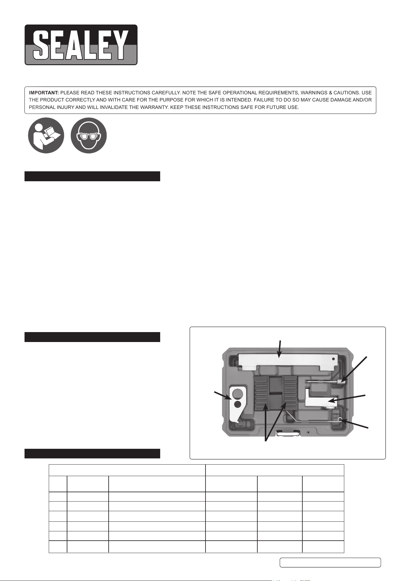
5.4. Using a suitable spanner on the auxiliary drive belt tensioner, rotate the tensioner in the direction shown in g.1 and lock in position
using VSE5006-01 Auxiliary Belt Tensioner Locking Pin.
5.5. Remove the auxiliary drive belt and remove the auxiliary belt tensioner whilst ensuring the Locking Pin VSE5006-01 is still in place.
5.6. Rotate the engine to TDC on No.1 cylinder. Ensure that the timing mark on the torsional vibration damper is aligned with the timing
mark on the lower timing belt housing. (g.2)
Original Language Version
© Jack Sealey Limited
VSE5006.V2 Issue 1 20/04/21
ENGINE CODES:
1.4 16V: G14D
1.6: A16LEL A16LER A16LET A16XER LDE/A16LER LDE/A16XER
LLU/A16LET Z16LEL Z16LER Z16LET Z16XE1 Z16XEP
Z16XER 192B3.000(Z16XEP)
1.6 ecoFLEX CNG: A16XNT LGE/A16XNT Z16XNT
1.8: 2HO/A18XEL 2HO/A18XER A18XER Z18XER 939A4.000
g.1
g.3
g.2
Make: Model: Year: Make: Model: Year:
Vauxhall/Opel Astra-G (03-10) Chevrolet Aveo (08-13)
Astra-H (04-13) Cruze (09-12)
Astra-J (09-13) Orlando (11-15)
Corsa-D (07-13)
Insignia (08-13) Saab 9-5 (10-12)
Meriva-A (06-10)
Signum (06-08) Alfa Romeo 159 (05-10)
Vectra-C (06-08)
Zara-B (05-13) Fiat Croma (06-11)
Zara-C Tourer (11-15) Stilo (05-08)
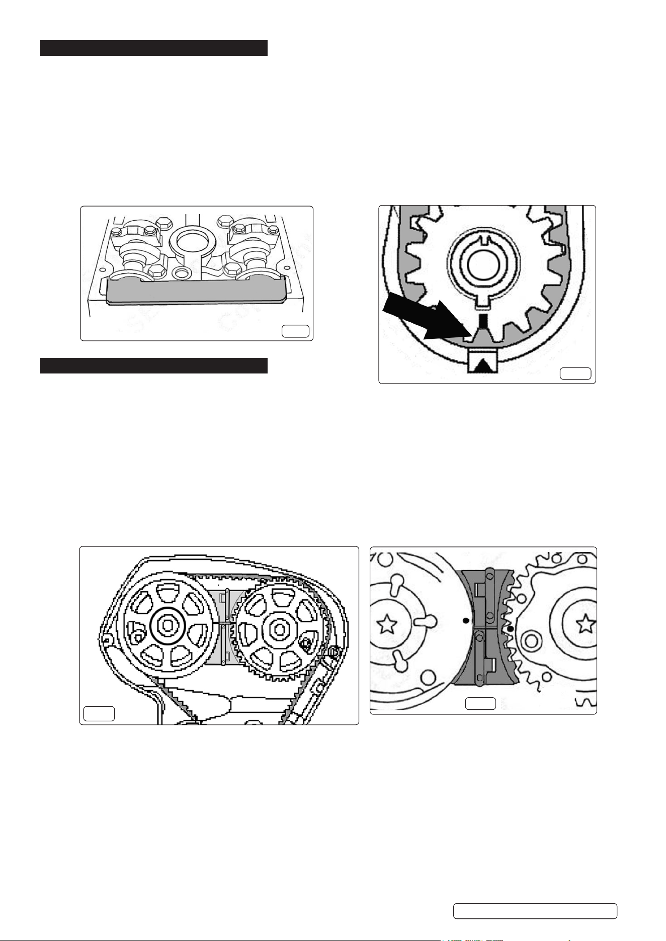
5.7. On the engine variants without VVT camshaft sprockets have timing lines which should be level and exactly opposite each other (g.3)
5.7.1. On the engine variants with VVT (XER) the camshaft sprockets have timing dots. The inlet camshaft sprocket dot should be slightly
higher than horizontal whilst the exhaust camshaft sprocket dot should be at the horizontal position.
5.8. Insert the VSE5006-04 Camshaft Sprocket Locking Tool between the camshaft sprockets, tting the exhaust side rst and then sliding
in the tool into the inlet side. The horizontal marking across the middle of the Camshaft Sprocket Locking Tool will give a
more accurate indication of the position of the timing lines or dots on the camshaft sprockets. (g.4)
5.9. Insert the ywheel holding tool depending on the type of vehicle into which the engine is tted (see note above).
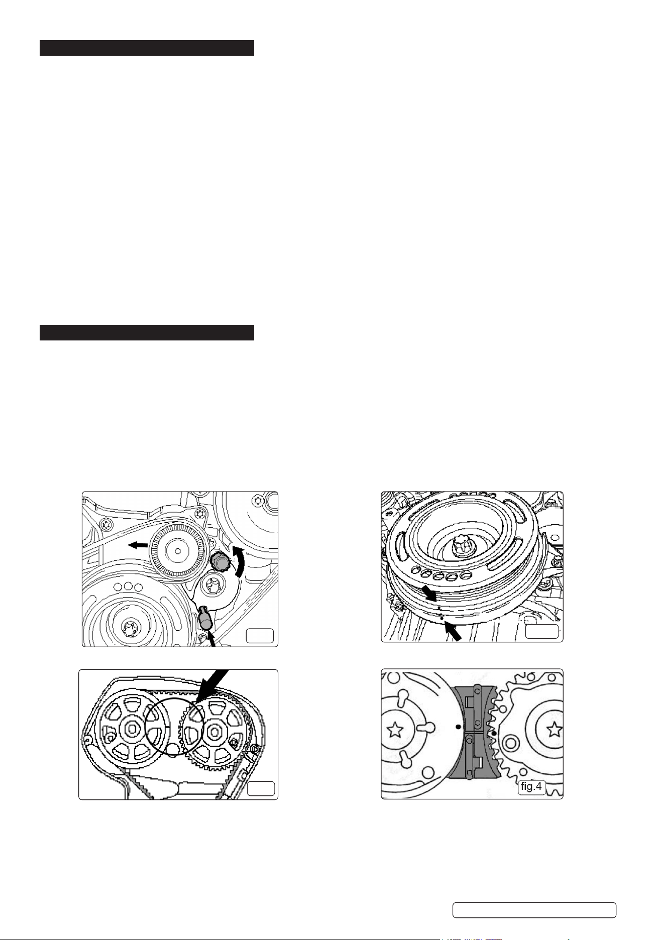
5.10. When tting the VSE5006-06 Flywheel Holding Tool it must be bolted in place (g.5). It slides in between the engine block and
sump faces. Remove the nut, slide in the tool so that it locks into the ywheel ring gear and hold in place with the nut.
5.10.1. If using the VSE5006-02 Flywheel Holding Tool; remove the protective cap, insert the tool so that it locks into the ywheel ring gear
and bolt into place .
5.11. Once the Flywheel Holding Tool is securely in place, remove the torsion vibration damper which is secured with one bolt.
5.12. Remove the lower section of the timing belt protective cover.
5.13. The engine position can be checked via the timing mark on the crankshaft gear aligning with the mark on the housing (g.6).
5.14. Using a hex key on the timing belt tensioner, relieve the tension from the timing belt and lock the timing belt tensioner in place with the
VSE5006-03 Timing Belt Tensioner Locking Pin (g.7).
5.15. Remove the timing belt.
6. TIMING BELT REPLACEMENT
NOTE: When tting the new timing belt use the protective sleeve supplied with the belt to avoid damage to the timing belt when threading it
through the engine mounting support. Remove the protective sleeve before tting the belt over the sprockets.
NOTE: When re-using a timing belt, ensure the previous direction of rotation is observed.
6.1. When tting the timing belt use the following sequence: start on the intake camshaft sprocket, then over the exhaust camshaft
sprocket, round the tensionless pulley and nally over the crankshaft sprocket.
6.2. Using a hex key, take sucient pressure from the timing belt tensioner to remove the timing belt tensioner locking pin. Remove the
timing belt tensioner locking pin and slowly release the tensioner so that it tensions the timing belt.
6.3. Fit the lower timing belt protective cover.
6.4. Re-install the torsional vibration damper ensuring the timing marks align. Use a NEW bolt and tighten to 95Nm + 30° + 15°.
6.5. Remove the ywheel locking tool and remove the camshaft sprocket locking tool.
6.6. Rotate the engine in the direction of rotation for 2 full cycles and return to TDC No.1 cylinder.
6.7. Check the position of the timing indicators on the camshaft sprockets and t the Camshaft Sprocket Locking Tool to conrm that
the engine timing is correct. Check that the mark on the torsional vibration damper aligns with the timing mark on the lower timing
belt protective cover.
6.8. Re-t the auxiliary drive belt tensioner, and install the auxiliary belt. Using a suitable spanner apply tension to the tensioner to
remove the pin and gently release the tensioner to apply tension to the auxiliary belt.
6.9. Re-t the upper section of the timing belt protective cover and re-t the air lter housing.
6.10. Reconnect the vehicle battery.
g.5
g.6
VSE5006.V2 Issue 1 20/04/21
Original Language Version
© Jack Sealey Limited
g.7
7. CHECK ENGINE TIMING
7.1. NON VVT ENGINES
7.1.1. Set the engine to TDC No.1 cylinder. Insert the VSE5006-04 Camshaft Sprocket Locking Tool.
7.1.2. Check that the timing lines correspond with the line on the Camshaft Sprocket Locking Tool and the mark on the crankshaft sprocket is
opposite the marker on the housing. If the marks are not aligned then it will be necessary to adjust the timing.
7.2. VVT (XER) ENGINES
7.2.1. The procedure is similar to that of the non VVT engines, but the VVT engines have dots instead of lines as described earlier (section
5.7.1.) which do not line up exactly with the centre line on the VSE5006-04 Camshaft Sprocket Locking Tool.
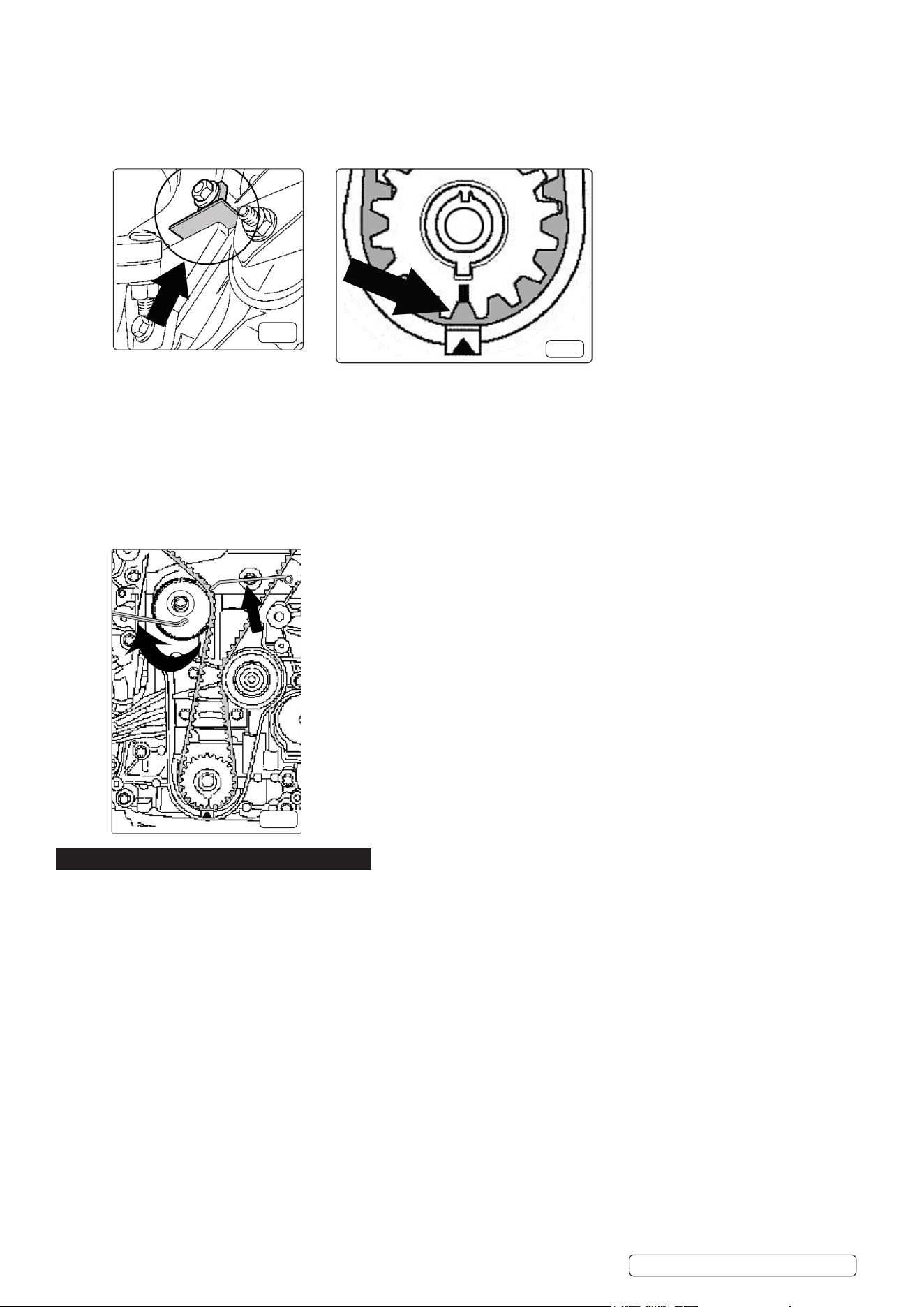
7.2.2. Remove the cylinder head cover and insert the VSE5006-05 Camshaft Setting Plate into the slots at the rear of the camshafts (g.8)
to see if the camshafts are aligned correctly. Check that the timing dots are aligned and the mark on the crankshaft sprocket is
opposite the marker on the housing (g.9).
7.2.3. If the timing dots are not correctly aligned, the Camshaft Setting Plate cannot be inserted or the mark on the crankshaft sprocket is
misaligned then it will be necessary to adjust the timing.
8. ADJUST ENGINE TIMING
8.1. NON VVT ENGINES
8.1.1. Timing adjustment is achieved by removing the timing belt, correctly aligning the crankshaft sprocket and the camshaft sprockets and
re-tting the timing belt.
8.1.2. Remove the timing belt as described in section 5.
8.1.3. If the camshaft sprockets are misaligned, adjust so that the timing marks are directly opposite. Use the centre line on the VSE5006-04
camshaft Sprocket Locking Tool to check the alignment (g.10) and check that the mark on the crankshaft sprocket is aligned with the
marker on the housing (g.11).
NOTE: The ywheel holding tool will have to be removed before rotating the crankshaft sprocket.
8.1.4. Once all timing marks are correctly aligned, t the ywheel locking tool and re-t the timing belt as described in section 6.
8.1.5. Remove Camshaft Sprocket Holding Tool and Flywheel Holding Tool.
8.1.6. Rotate the engine in the direction of rotation for 2 full cycles and return to TDC No.1 cylinder.
8.1.7. Check the position of the timing marks on the camshaft sprockets and t the Camshaft Sprockets Locking Tool to conrm that the
engine timing is correct.
8.1.8. Remove Camshaft Sprockets Locking Tool, remove Flywheel Locking Tool and re-t components as described in section 6.
8.2. VVT (XER) Engines
NOTE: The ignition module will need to be removed from the top of the engine to allow access to the camshafts.
8.2.1. Remove the timing belt as described in section 5.
8.2.2. Remove the cylinder head cover and adjust the position of the cams so that the VSE5006-05 Camshaft Setting Plate can be inserted
into the slots at the rear of the camshafts. Check that the timing dots on the camshaft sprockets are in the correct position (g.11).
8.2.3. Check that the mark on the crankshaft sprocket aligns with the marker on the housing (g.9) If the position of the crankshaft needs to
be adjusted in will be necessary to remove the Flywheel Holding Tool.
8.2.4. Once all timing marks are correctly aligned, re-t the Flywheel Holding Too and re-t the timing belt as described in section 6.
8.2.5. Remove Camshaft Sprocket Holding Tool and Flywheel Holding Tool.
8.2.6. Rotate the engine in the direction of rotation for 2 full cycles and return to TDC No.1 cylinder.
8.2.7. Check the position of the timing dots on the camshaft sprockets and t the Camshaft Sprockets Locking Tool and the VSE5006-05
Camshaft Setting Plate to conrm that the engine timing is correct.
8.2.8. Remove camshaft sprockets locking tool and the camshaft setting plate, and re-t components as described in section 6.
g.8
g.9
VSE5006.V2 Issue 1 20/04/21
Original Language Version
© Jack Sealey Limited
g.10
g.11

Sealey Group, Kempson Way, Suffolk Business Park, Bury St Edmunds, Suffolk. IP32 7AR
01284 757500 01284 703534 sales@sealey.co.uk www.sealey.co.uk
ENVIRONMENT PROTECTION
Recycle unwanted materials instead of disposing of them as waste. All tools, accessories and packaging should be sorted, taken to
a recycling centre and disposed of in a manner which is compatible with the environment. When the product becomes completely
unserviceable and requires disposal, drain any fluids (if applicable) into approved containers and dispose of the product and fluids
according to local regulations.
Note: It is our policy to continually improve products and as such we reserve the right to alter data, specifications and component parts without prior
notice. Please note that other versions of this product are available. If you require documentation for alternative versions, please email or call
our technical team on technical@sealey.co.uk or 01284 757505.
Important: No Liability is accepted for incorrect use of this product.
Warranty: Guarantee is 12 months from purchase date, proof of which is required for any claim.
VSE5006.V2 Issue 1 20/04/21
Original Language Version
© Jack Sealey Limited