1. SAFETY
WARNING! Wear approved eye protection. Wear appropriate Personal Protective Equipment. A full range of Personal Protective
Equipment is available from your Sealey stockist.
WARNING! Ensure that Health & Safety, Local Authority Regulations and general workshop practice Regulations are adhered to
when using tools.
8 DO NOT use tools if damaged.
9 Maintain tools to ensure that they are in an adequate condition for safe use and optimum performance.
9 Ensure that a vehicle that has been raised by a jack is adequately supported. Use axle stands.
9 Wear suitable clothing to avoid snagging. DO NOT wear jewellery. Tie back long hair.
9 Account for all tools, parts and components being used. DO NOT leave these in or near the engine. Return tools to suitable
storage after use.
9 These Instructions are provided as a guide only.
9 Always refer to the vehicle manufactures’ service instructions or a proprietary manual to establish the correct procedure and
data.
WARNING! The warnings, cautions and instructions in this manual cannot cover all possible conditions and situations. The Operator/
user must apply caution and common sense (good practical sense).
WARNING! Incorrect or out of phase camshaft timing can result in contact between the valve head and the piston crown. This will
cause damage to the engine.
2. INTRODUCTION
Comprehensive kit covering engine timing and belt replacement on VAG 1.2-2.0D Pumpe Duse and 1.2, 1.6, 2.0D common rail diesel
engines. Also covers these engines tted in Ford, Dodge and Mitsubishi models. Kit contains crankshaft locking tools for both oval and round
crank gears, camshaft locking pins and tensioner adjustment tools. Supplied in storage case.
Associated Tool:
VSE5852 ‘Service Position’ Front End Support Guide Set.
These guides are required to support the front panel when it is extended to provide increased access space in the engine compartment during
timing belt replacement eg. on Audi A4, A6, VW Passat, and also to carry out various service applications on a number of other VAG models.
OEM Tool Part Numbers: 3369, 3341, U-40050, T10093, T20167, T30092.
TIMING TOOL KIT - FOR VAG, DODGE, FORD,
MITSUBISHI - 1.2D/1.4D/1.6D/1.9D/2.0D - BELT
DRIVE
MODEL No: VSE5951.V2
Thank you for purchasing a Sealey product. Manufactured to a high standard, this product will, if used according to these
instructions, and properly maintained, give you years of trouble free performance.
IMPORTANT: PLEASE READ THESE INSTRUCTIONS CAREFULLY. NOTE THE SAFE OPERATIONAL REQUIREMENTS, WARNINGS & CAUTIONS. USE
THE PRODUCT CORRECTLY AND WITH CARE FOR THE PURPOSE FOR WHICH IT IS INTENDED. FAILURE TO DO SO MAY CAUSE DAMAGE AND/OR
PERSONAL INJURY AND WILL INVALIDATE THE WARRANTY. KEEP THESE INSTRUCTIONS SAFE FOR FUTURE USE.
Refer to
Instructions
Wear Eye
Protection
VSE5852 ‘Service Position’ Front End
Support Guide Set.
Original Language Version
© Jack Sealey Limited
VSE5951.V2 Issue 1 21/06/23
OEM Tool Part Number
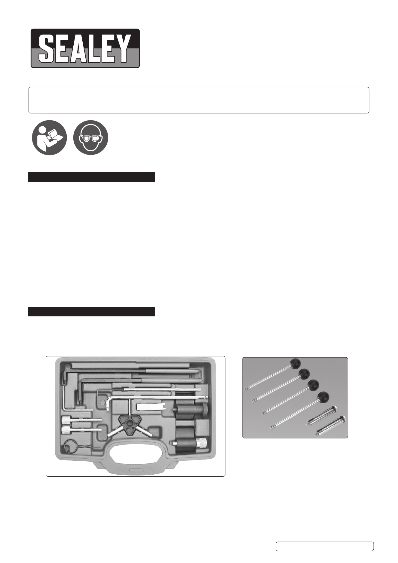
Item Part Number Description VAG Dodge Ford Mitsubishi
1 VSE5951-V2-01 Crankshaft Locking Tool (Oval Gears) T10100 - - -
2 VSE5951-V2-02 Crankshaft Locking Tool (Round Gears) T10050 9883 310-085, 23-059 MB995209
3 VSE5951-V2-03 Camshaft Locking Pin (2 per kit*) 3359, T20102 9882 - MB995206
4 VSE5951-V2-04 Tensioner Adjuster 3387, U-30009A - 303-1053 MB995207
5 VSE5951-V2-05 Tensioner Adjuster T10020 - - -
6 VSE5951-V2-06 Tensioner Adjuster T10264 - - -
7 VSE5951-V2-07 Tensioner Locking Tool T10265 - - -
8 VSE5951-V2-08 Tensioner Locking Pin (Mechanical) T10115 - 303-1054 -
9 VSE5951-V2-09 Tensioner Locking Tool (Hydraulic) T10008 - 310-084, 23-058 -
10 VSE5951-V2-10 Tensioner Setting Tool (Hydraulic) - - - -
11 VSE5951-V2-11 Auxiliary Belt Locking Pin T10060A, T40098,
T20167
- - -
*These spares are sold as individual tools - not as pairs or multiples.
3. CONTENTS
4. APPLICATIONS
MAKE MODEL
Audi A1/Sportback (10-15), A2 (01-06), A3/Sportback (01-15), A4/Allroad (99-16), A5 (08-12), A5 Sportback (09-15),
A5 Cabriolet (12-15), A6/Allroad (98-11), TT (08-14), Q3 (11-15), Q5 (08-15)
Seat Alhambra (99-15), Altea/Altea XL (04-15), Arosa (99-05), Cordoba (02-09), Exeo (09-14), Ibiza (02-15), Leon
(00-12), Toledo (00-11)
Skoda Fabia (00-07), Fabia II (07-15), Octavia (00-10), Octavia II (04-13), Praktik (10-15), Rapid (12-15), Rapid Space-
back (13-15), Roomster (07-15), Superb (02-08), Superb II (08-15), Yeti (09-12)
VW Amarok (10-16), Beetle (00-11), Bora (98-08), Caddy/Maxi (03-15), Eos (06-15), Fox (05-11), Golf (98-12), Golf
Plus (05-12), Jetta (05-11), Lupo (99-05), Passat/CC (98-15), Polo (99-12), Scirocco (08-12), Sharan (99-15),
Tiguan (07-15), Touran (03-15), Transporter (03-19)
Dodge Caliber (06-11)
Ford Galaxy (99-06)
Mitsubishi Grandis (05-10), Lancer (05-10), Outlander (07-10)
ENGINE CODES
1.2D TDi PD (Pump Dose) ANY, AYZ
1.4D TDi PD AMF, ATL, BAY, BHC, BMS, BNM, BNV, BWB
1.9D TDi PD AJM, ANU, ARL, ARX, ASZ, ATD, ATJ, AUY, AVB, AVF, AVQ, AWX, AXB, AXC, AXR, BJB, BKC, BKE, BLS, BLT,
BMT, BPX, BPZ, BRB, BRM, BRR, BRS, BRU, BSU, BSV, BSW, BTB, BUK, BVK, BXE, BXF, BXJ
2.0D TDi PD AZV, BEW, BKD, BDJ, BDK, BGW, BHW, BKP, BLB, BMA, BMM, BMN, BMP, BMR, BNA, BPW, BRC, BRD,
BRE, BRF, BRT, BSS, BST, BUY, BUZ, BVA, BVE, BVF, BVG, BVH, BWV
2.0D Di-D/CRD ECD(BSY), ECD(BYL), ECE(BWD), BSY, BWC
1.2D TDi CR (Common Rail) CFWA
1.6D TDi CR CAYA, CAYB, CAYC, CAYD, CAYE, CLNA
2.0D TDi CR CAAA, CAAB, CAAC, CAAE, CAGA, CAGB, CAGC, CAHA, CAHB, CBAA, CBAB, CBAC, CBBA, CBBB, CBDA,
CBDB, CBDC, CBEA, CCHA, CCHB, CDBA, CDCA, CEGA, CFCA, CFFA, CFFB, CFFD, CFFE, CFGB, CFGC,
CFHA, CFHB, CFHC, CFHE, CFHF, CFJA, CGLA, CGLB, CJAA, CJCA, CJCC, CJCB, CJCD, CLCA, CLCB,
CLJA, CMEA, CSHA
Original Language Version
© Jack Sealey Limited
VSE5951.V2 Issue 1 21/06/23
5. INSTRUCTIONS
5.1. VSE5951 Setting/Locking Kit provides a comprehensive
selection of the timing tools required for engine timing
and belt replacement on a huge range of VAG Pumpe
Düse and Common Rail diesel engines - 1.2TDi to 2.0TDi.
Many changes have been introduced on these engines
since their initial release in 1998, example: “round” or
“oval” crankshaft gears. The VSE5951 kit provides tools
applicable across this complete range of variants, and
therefore it is important that the correct tools are selected
from the kit to suit the engine size and variant being
worked on.
Always refer to the appropriate service data from the
manufacturer and also use the Contents/OE Tool
Number cross reference chart provided to identify and
select the correct tools from the kit.
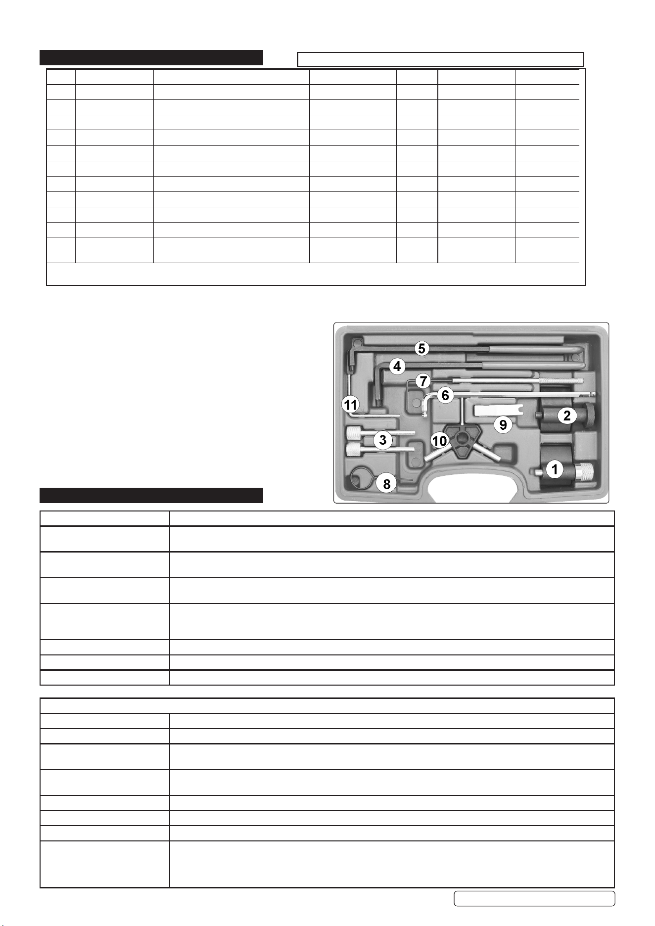
5.1.1. Variants to watch for…..
Crankshaft gears.
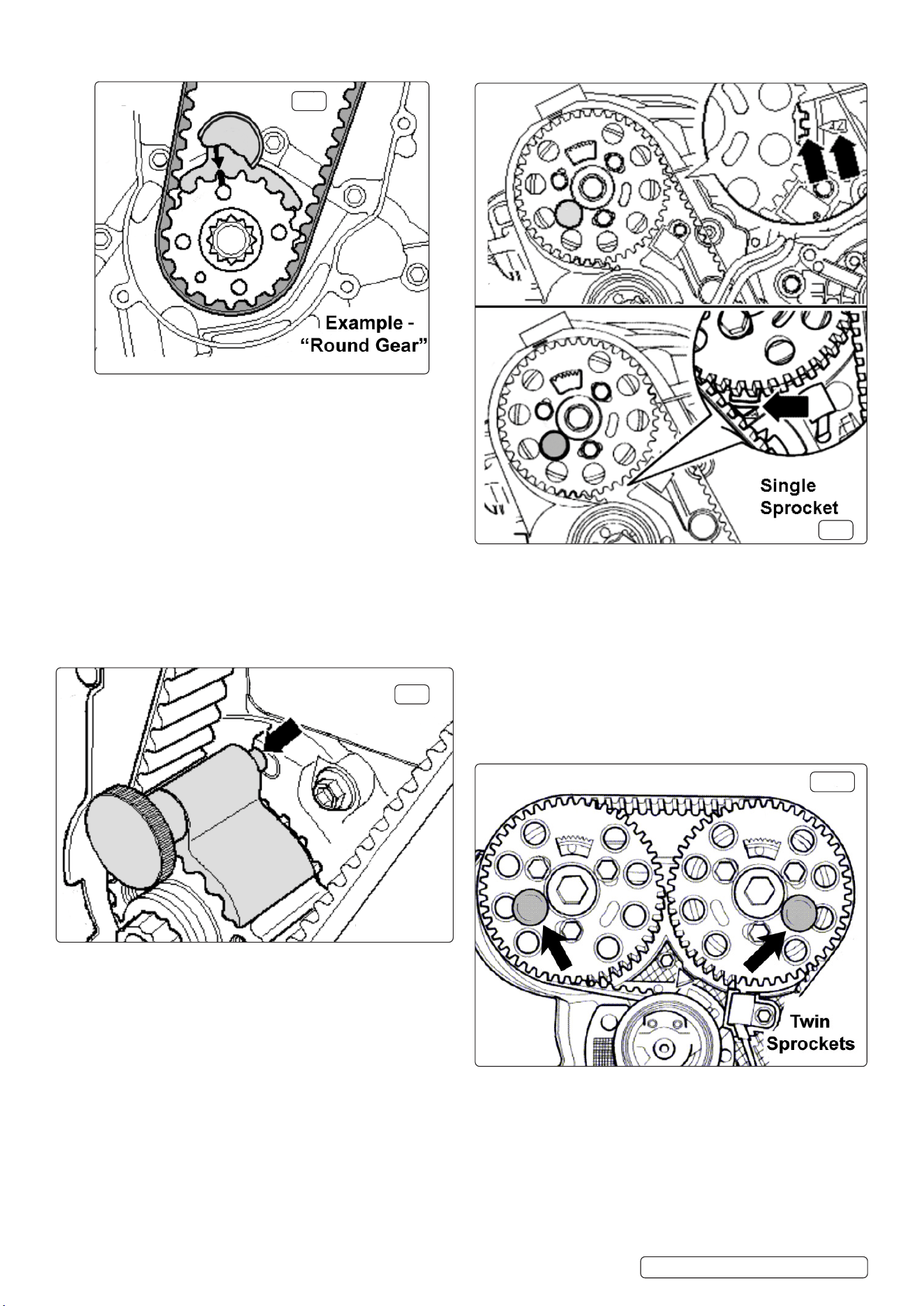
Roundgear(g.1A).
VSE5951-V2-02 TDC timing marks align at 12 o’clock
position.
Ovalgear(g.1B).
VSE5951-V2-01 - TDC timing marks align at 1 o’clock
position.
g.1A
g.1B
VSE5951-V2-03 Locking Pins
(g.2A) Single sprocket - 1 Pin
(g.2B) Twin sprockets - 2 Pins
(g.2C) CR - Single sprocket & HP Pump sprocket - 2 Pins
5.1.3. Belt tensioners.
g.2C
g.2A
g.2B
g.3A
5.1.2. Camshaft sprockets.
Early engines - hydraulic tensioners (g.3A)
VSE5951-V2-09 Locking Tool
VSE5951-V2-04 Adjuster
VSE5951-V2-10 Setting Tool
Original Language Version
© Jack Sealey Limited
VSE5951.V2 Issue 1 21/06/23
g.3B
g.4
g.5
g.6
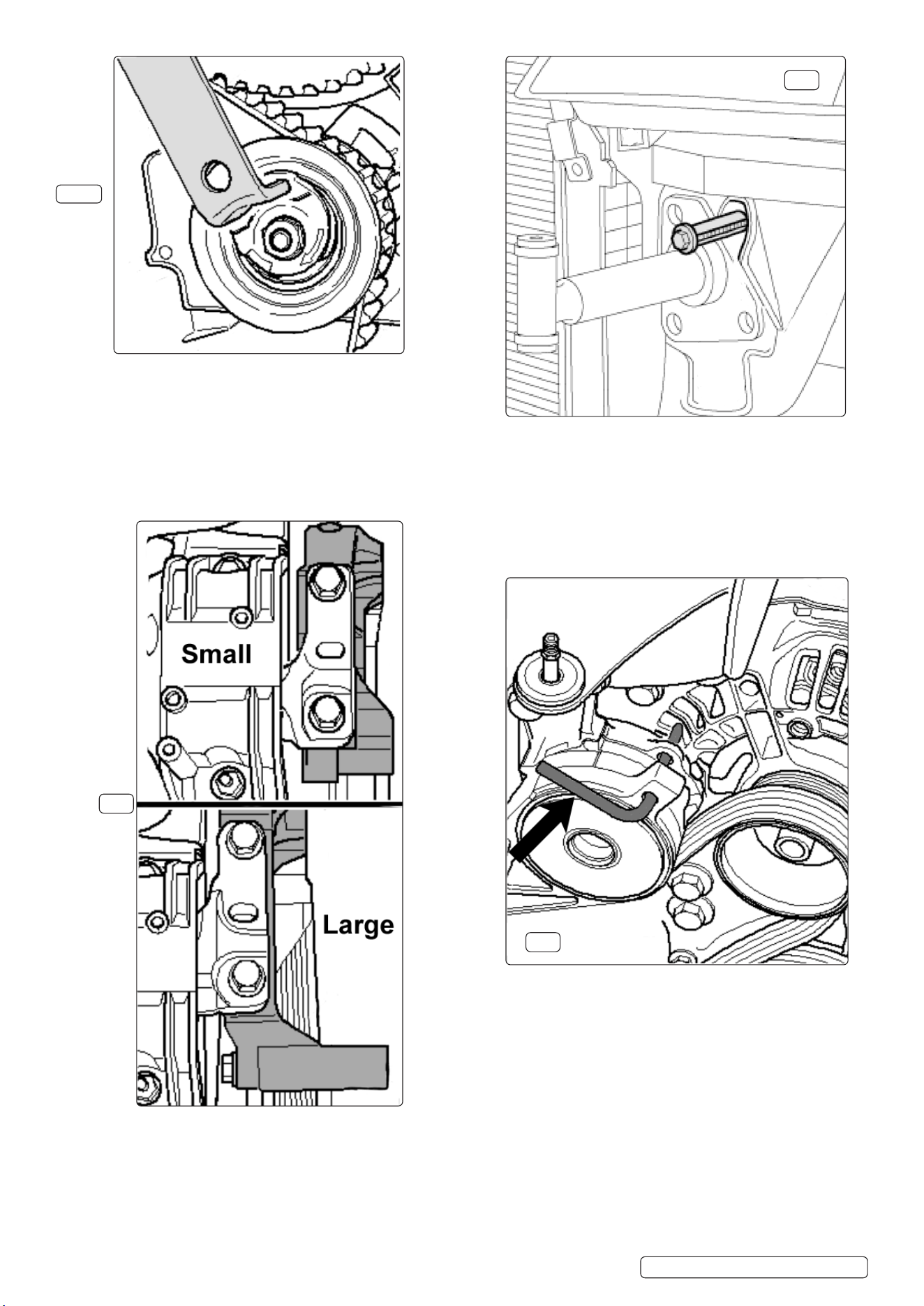
5.1.4. Larger engine mount – allows removal of belt without
removing mount.
5.2. ASSOCIATED TOOL – VSE5852
‘Service Position’ Front End Support Guide Set.
These guides are required to support the front panel when
it is extended to provide increased access space in the
engine compartment during timing belt replacement eg. on
Audi A4, A6, VW Passat, and also to carry out various
service applications on a number of other VAG models.
Special tensioner tools required to access tensioner.
VSE5951-V2-07 Locking Tool
VSE5951-V2-06 Adjuster
5.3. VSE5951-V2-11 Auxiliary Belt Tensioner Locking Pin.
VSE5951-V2-11 Locking Pin is required to be used on
almost all of these engines as the auxiliary tensioner
must be ‘locked’ and removed together with the belt
to give access to the timing belt (g.6).
Later engines- mechanical (friction dampened) tensioners
(g.3B)
VSE5951-V2-08 Locking Pin
VSE5951-V2-04 Adjuster
VSE5951-V2-05 Adjuster
Original Language Version
© Jack Sealey Limited
VSE5951.V2 Issue 1 21/06/23
5.4.1. VSE5951-V2-02 and VSE5951-V2-01 Crankshaft
locking Tools.
There are two types of crankshaft gear - ‘round’ or ‘oval’,
and it is imperative that the correct Crankshaft Locking
Tool from the VSE5951 kit is selected and used on the
appropriate gear. Using the incorrect Locking Tool will
cause engine damage.
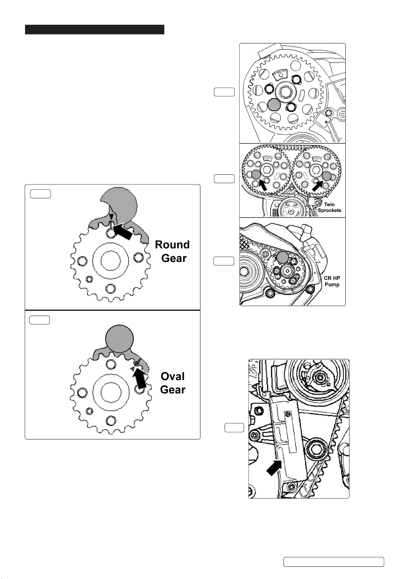
IMPORTANT: The crankshaft must be positioned at TDC
prior to the tool being tted. The tool is tted onto the
gear in a position where the timing mark on the Locking
Tool is aligned with the mark on the crankshaft gear
(g.7 example - round gear timing mark).
NOTE: These tools can only be tted correctly to the
crankshaft gear by sliding the tool into the gear teeth
from the front face of the gear. The tool will not locate
correctly by being tted on top of the gear.
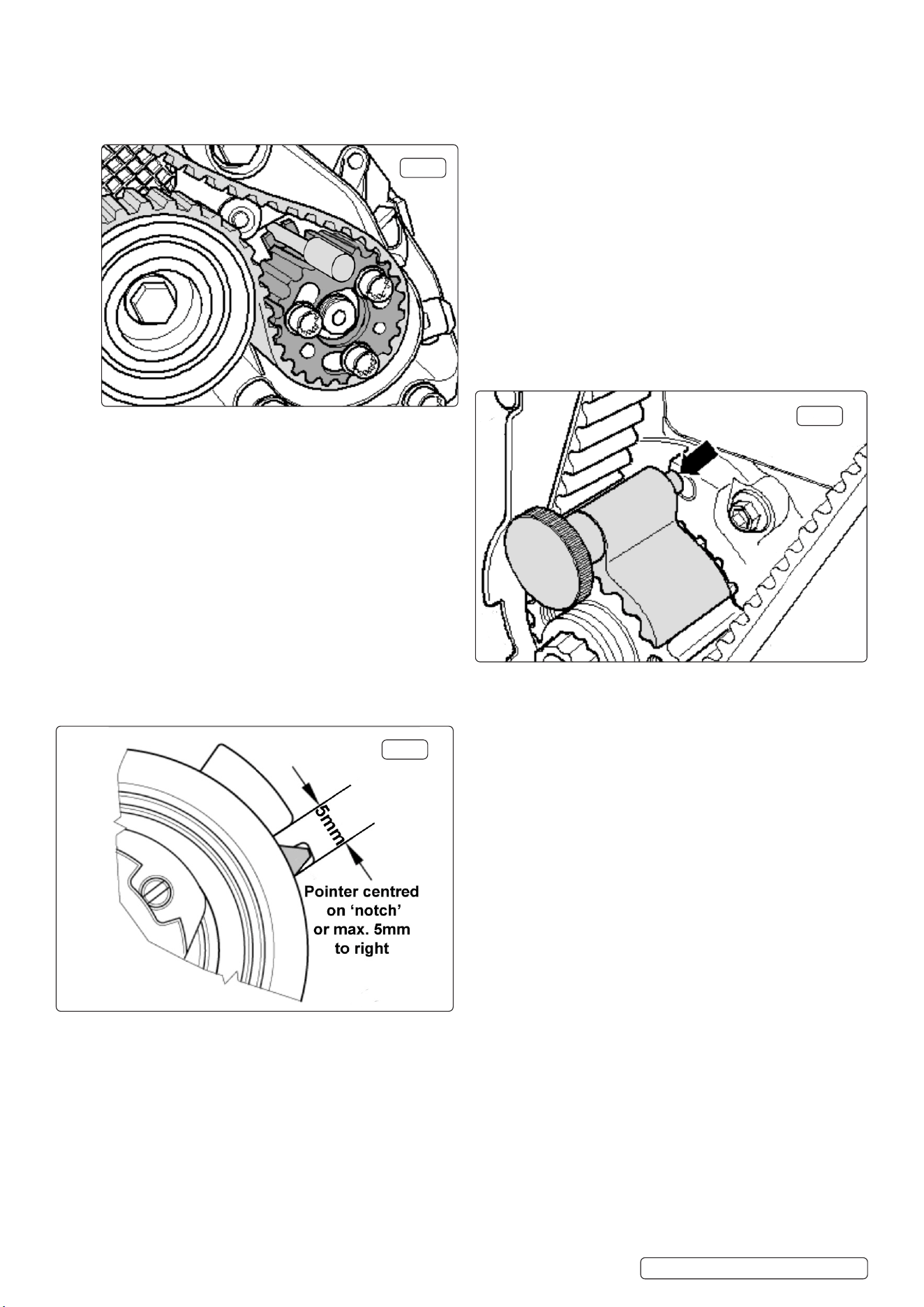
5.4.2. The crankshaft is turned clockwise to TDC No.1 cylinder
and conrmed by the camshaft sprocket timing marks/
position. The crankshaft is locked in position by sliding the
locking tool into the crank gear teeth and at the same
time locating the rear lug of the Locking Tool into the hole
in the oil seal housing (g.8).
g.8
g.9
g.10
5.5.1. VSE5951-V2-03 Camshaft Locking Pins (2 per kit).
On engines with a single camshaft the timing position is
correct when the gear window is at the top and the
timing marks (rear belt cover/camshaft sensor wheel)
are aligned. Marks can be “3Z” - 3 cyl. engines (on the
left side), or “4Z” – 4 cyl. engines (on the right side), or
also as shown in g.9.
5.5.2. The Camshaft Locking Pin (one pin) is inserted into the
free hole on the left hand side of the sprocket. To ‘lock’
the camshaft the Pin is pushed through the sprocket
and through the sprocket hub to locate into the timing
hole in the cylinder head.
5.5.3. For twin camshaft engines (16v.) timing position is
correct when the gear windows are at the top and
timing marks on the rear belt cover/camshaft sensor
are aligned. The Camshaft Locking Pins (two pins) are
inserted into the free holes in each sprocket – the hole
on the left hand side of the exhaust camshaft sprocket
and the right hand side of the inlet camshaft sprocket.
To ‘lock’ the camshafts the Pins are pushed through the
sprockets and through the sprocket hubs to locate into
the timing holes in the cylinder head (g.10).
g.7
5.4. Crankshaft timing positions. 5.5. Camshaft timing positions.
Original Language Version
© Jack Sealey Limited
VSE5951.V2 Issue 1 21/06/23
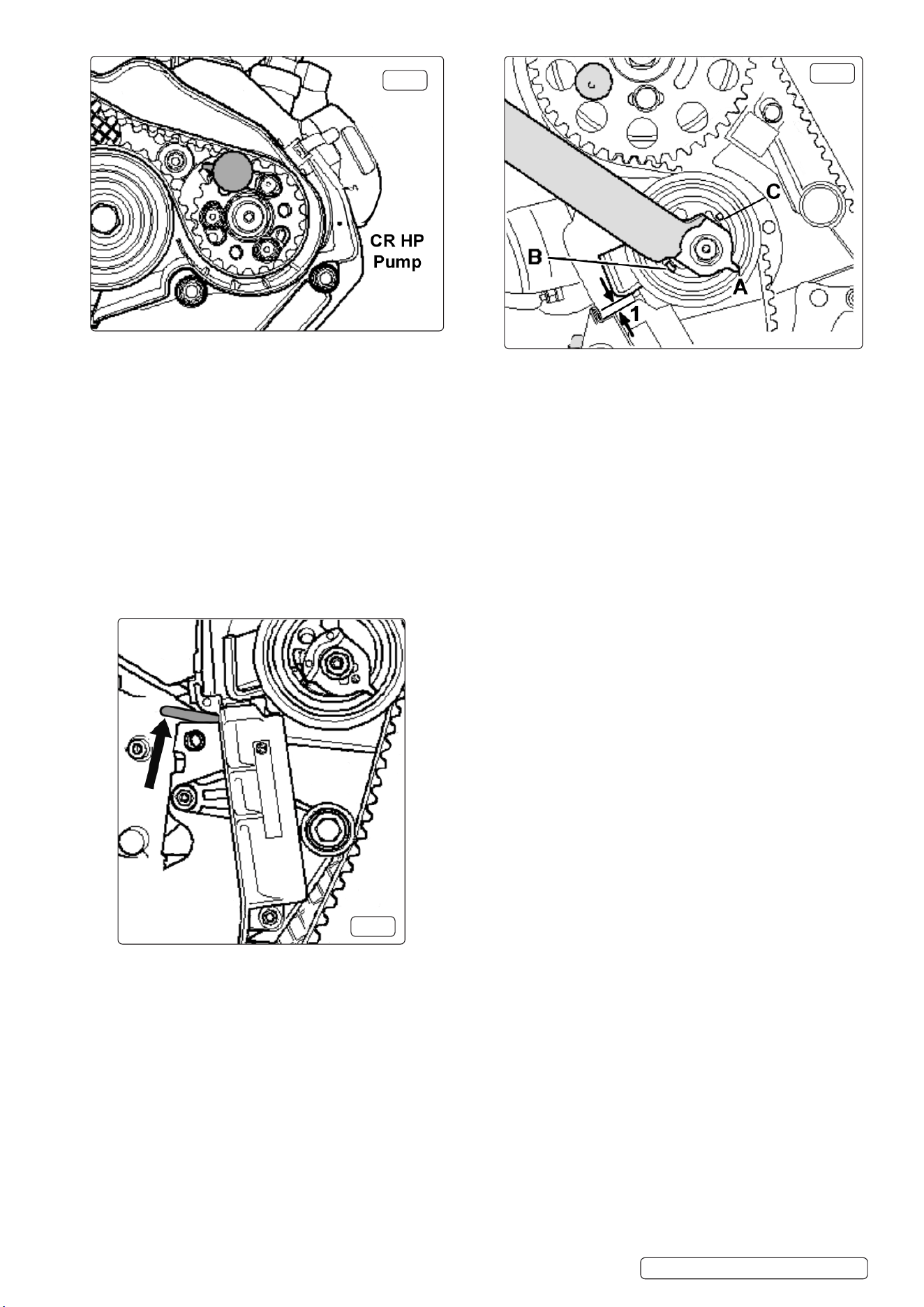
5.6.2. Then using VSE5951-V2-04 Adjuster the tensioner eccen-
tric is turned clockwise until pointer “A” comes to a stop at
position “B” (g.13).
The new timing belt is tted, ensuring it is taut between
sprockets on the non-tensioner side.
VSE5951-06 Adjuster is used to turn the eccentric
anticlockwise towards “C” until VSE5951-V2-09 Locking
Tool can be removed. NOTE: The eccentric is
restrained in this position using VSE5951-V2-04 Adjuster.
5.7. VSE5951-V2-10 Tensioner Setting Tool.
5.7.1. VSE5951-07 Setting Tool comprises 4mm, 7mm and
8mm set pins which are used to set the gap on hydraulic
tensioners, at position “1” (g.13).
For Pumpe Düse engines the settings are:
Engine codes ANY and AYZ 7mm ± 1mm.
Engines with hydraulic tensioner EXCEPT
codes ANY/AYZ 4mm ± 1mm.
g.11
g.12
g.13
5.5.4. On common rail engines both Locking Pins are used.
One to ‘lock’ the camshaft sprocket and the other Pin
the ‘lock’ the HP pump sprocket – also driven by the
timing belt.
5.5.5. The camshaft timing position is correct when the arrow
on the camshaft sprocket is pointing upwards, or the
gear window is at the top. The camshaft locking pin is
inserted through the sprocket and through the sprocket
hub to locate into the timing hole in the cylinder head.
5.5.6. The HP pump is ‘locked’ in position, using the 2nd
VSE5951-01 Pin, and then the 3 retaining bolts are
released, prior to the new belt being tted (g.11) - also
see “Timing Belt Installation, Common Rail engines”.
5.6. Hydraulic Tensioners – Early Pumpe Düse engines.
VSE5951-V2-09 Tensioner Locking Tool
VSE5951-V2-04 Tensioner Adjuster
VSE5951-V2-10 Tensioner Setting Tool
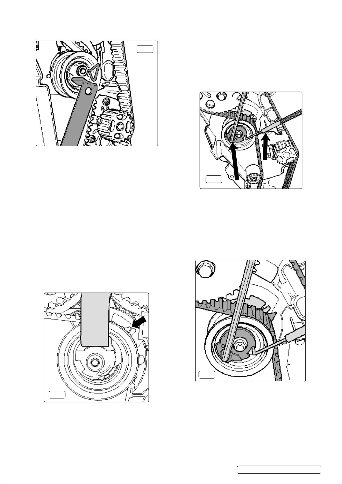
5.6.1. Early Pumpe Düse engines have hydraulic (automatic)
belt tensioners. In order to release tension for removal
of the belt, the tension eccentric is turned anticlockwise
so to depress the tensioner unit sufciently to insert
VSE5951-V2-09 Locking Tool (g.12).
The tensioner unit can then be removed together with
the old timing belt. When installing a new belt the
camshaft sprocket bolts are released and the sprocket
turned clockwise until the bolts are at the end of the
elongated holes. Camshaft sprocket bolts should be
replaced with new bolts.
5.7.2. The appropriate set pin size is inserted into position
“1” and the VSE5951-06 Adjuster allowed to move
slowly in a clockwise direction adjusting the gap at
position “1” to the set pin diameter. The tensioner
locking nut is then tightened.
The tensioner dimension at position “1” must be
checked after tightening the camshaft sprocket bolts,
removing all locking tools and turning the engine over
twice, by hand, and returning to the TDC No.1 cylinder
position.
NOTE: A suitable Holding Tool must be used on the
camshaft sprocket when tightening the sprocket bolts.
Original Language Version
© Jack Sealey Limited
VSE5951.V2 Issue 1 21/06/23
5.8.5. Counter hold the camshaft sprocket(s) with a suitable
Holding Tool and tighten the sprocket bolts.
All locking tools should be removed, the engine turned
over twice, by hand, and returned to TDC No.1 cylinder.
Check that crankshaft and camshaft timing tools can
be easily tted, and that the tensioner pointer is aligned
with the “notch”.
5.9. Change of Engine Mounting – Revised belt tensioner
- Later Pumpe Düse engines/Common Rail engines.
VSE5951-V2-07 Tensioner Locking Tool
VSE5951-V2-06 Tensioner Adjuster
5.9.1. On a number of models (from 2004) a larger engine
mounting was introduced. With these new larger
mountings the revised routing of the timing belt has
resulted in removal and tting of the belt without the
need to remove or detach the engine mounting.
At the same time a new belt tensioner was introduced
together with new tensioner tools which are required to
gain access to the tensioner in the limited space available.
5.9.2. VSE5951-06 Tensioner Adjuster locates into the
hexagon provided on the tensioner in order to turn the
tensioner for release or to apply belt tension.
VSE5951-07 Tensioner Locking Tool ‘locks’ the tensioner
in a position off the timing belt allowing the belt to be
removed.
VSE5951-V2-08 Tensioner Locking Pin
VSE5951-V2-04 Tensioner Adjuster
VSE5951-V2-05 Tensioner Adjuster
5.8.1. Before releasing the tensioner to remove the old timing
belt, the crankshaft and camshaft locking tools must be
in place and the camshaft sprocket bolts released so that
the sprocket(s) can be turned within the elongated holes.
NOTE: the sprocket(s) should be able to turn but not tilt.
5.8.2. The tensioner nut is slackened and either VSE5951-04
or VSE5951-05 Adjuster (whichever suits the application
best), is used to turn the tensioner anticlockwise until
VSE5951-08 Locking Pin can be inserted (g.14).
The tensioner is then turned clockwise to the stop and
the tensioner nut tightened.
The old timing belt can now be removed and the camshaft
sprocket(s) turned clockwise in the elongated holes in
the sprocket(s).
5.8.3. It is advisable to check that the tensioner retaining lug is
fully engaged into the rear belt cover. The new belt is
tted and the tensioner nut released.
g.15
g.16
g.17
5.8. Mechanical Tensioners (friction dampened) – Later
Pumpe Düse engines.
g.14
5.8.4. The tensioner is turned anticlockwise using the Adjuster
until the Tensioner Locking Pin can be removed and the
tensioner is turned clockwise until a position is achieved
where the pointer is aligned with the “notch” in the back
plate (g.15).
Original Language Version
© Jack Sealey Limited
VSE5951.V2 Issue 1 21/06/23
g.19
5.10. Timing Belt Installation, Common Rail engines.
5.10.1. Prior to tting a new belt on common rail engines, the 3
bolts on the camshaft sprocket and the 3 bolts on the HP
pump are loosened, allowing the sprocket to turn but not
tilt.
5.10.2. The crankshaft must be ‘locked’ using the correct
Locking Tool and VSE5951-07 Tensioner Locking Tool
should be inserted in the belt tensioner, and Locking Pins
VSE5951-01 inserted through the camshaft sprocket and
HP pump sprocket (g.18).
NOTE: The camshaft sprocket and HP pump sprocket
should be turned in their elongated holes clockwise to
the “stop”.
5.10.3. The new belt is tted in order - crankshaft gear, tensioner,
camshaft sprocket, coolant pump sprocket, HP pump
sprocket and nally, idler roller.
The tensioner is released and VSE5951-07 Locking Tool
pulled out. A suitable Sprocket Holding Tool is attached to
the camshaft sprocket and pressure applied in an
anticlockwise direction to maintain tension on the
sprocket/belt whilst tightening the camshaft sprocket bolts
and HP pump sprocket bolts. NOTE: Always t new bolts.
5.10.5. Remove all timing tools and turn the engine over twice,
by hand, returning to TDC No.1 cylinder.
Fit the crankshaft and camshaft locking tools to check
engine timing is correct, and also check that the tensioner
pointer is centred (or a maximum of 5mm. to the right) of
the “notch” on the back plate.
If there is any difculty tting the timing tools – refer to
“Adjusting Timing” sections
5.11. Adjusting Timing - 8v. single camshaft Pumpe Düse
engines.
5.11.1. Once the correct Crankshaft Locking Tool has been tted
to the crankshaft gear and has ‘locked’ the engine at
TDC No.1 cylinder, the Camshaft Locking Pin is inserted
through the camshaft sprocket.
If the Locking Pin cannot be inserted easily to ‘lock’ the
camshaft – then timing adjustment will be necessary.
Adjust the timing as follows:
5.11.2. The Crankshaft Locking Tool is pulled forward on the
crankshaft gear in order that it is no longer engaged in
the hole in the oil seal housing, and therefore not
‘locking’ the crankshaft.
The crankshaft can then be turned slowly until the
Camshaft Locking Pin can be inserted.
The 3 camshaft bolts are loosened, allowing the
sprocket to turn in the elongated holes in the sprocket.
5.11.3. The crankshaft is turned slowly in an anticlockwise
direction until the lug in the back of the Crankshaft
Locking Tool slightly passes the hole in the oil seal
housing and then the crankshaft is turned clockwise
until the Locking Tool can be inserted into the hole to
‘lock’ the crankshaft.
5.11.4. Using a suitable Holding Tool counter hold the camshaft
sprocket and tighten the camshaft sprocket bolts.
NOTE: Always t new sprocket bolts.
5.11.5. Once completed, all the tools are removed and the
engine turned over twice, by hand, returning to TDC No.1
cylinder, and the timing tools installed to check the
engine timing position.
5.12. Adjusting Timing - 16v. twin camshaft Pumpe Düse
engines.
5.12.1. Once the correct Crankshaft Locking Tool has been
tted to the crankshaft gear and has ‘locked’ the engine
at TDC No.1 cylinder, the Camshaft Locking Pins are
inserted through the camshaft sprockets.
g.20
5.10.4. The belt tensioner is turned clockwise using VSE5951-06
Adjuster until the pointer aligns with the “notch” on the
back plate. Ensure the retaining nut does not turn, and
whilst maintaining this position, tighten the tensioner
nut.
IMPORTANT: The tensioner pointer position must be
maintained whilst tightening the tensioner nut. The
tensioner pointer may be allowed to move clockwise a
maximum of 5mm. to the right of the “notch”. This will
correct after the engine has run for a short time (g.19).
g.18
Original Language Version
© Jack Sealey Limited
VSE5951.V2 Issue 1 21/06/23
5.12.2. (1) If the Locking Pin cannot be inserted easily to ‘lock’
the right hand camshaft - then timing adjustment will
be necessary, as follows:
The 3 bolts of the right hand sprocket are loosened,
allowing the sprocket to turn in the elongated holes in
the sprocket. Use a spanner on the centre bolt and
turn the sprocket until the Locking Pin can be inserted.
Using a suitable Holding Tool counter hold the camshaft
sprocket and tighten the sprocket bolts.
NOTE: Always t new sprocket bolts.
Once completed, all the tools are removed and the
engine turned over twice, by hand, returning to TDC
No.1 cylinder, and the timing tools installed to check
the engine timing position.
NOTE: also check the tensioner pointer is aligned with
“notch”
5.12.3. (2) If the camshaft sprocket Locking Pins can be
inserted BUT the Crankshaft Locking Tool cannot be
correctly tted - adjust the timing as follows:
Insert the Camshaft Locking Pins to ‘lock’ both camshafts
and release the 6 bolts allowing the sprockets to turn in
the elongated holes.
Turn the crankshaft in normal direction of engine rotation
to t the Crankshaft Locking Tool and using a suitable
Holding Tool counter hold the camshaft sprockets and
tighten the sprocket bolts.
NOTE: Always t new bolts.
Once completed, all the tools are removed and the
engine turned over twice by hand, returning to TDC
No.1 cylinder, and the timing tools installed to check
the engine timing position.
NOTE: also check the tensioner pointer is aligned with
“notch”.
5.13. Adjusting Timing – 16v. 1.2, 1.6, 2.0 Common Rail
engines.
5.13.1. Once the correct Crankshaft Locking Tool has been
tted to the crankshaft gear and has ‘locked’ the engine
at TDC No.1 cylinder, the Camshaft Locking Pin is
inserted through the camshaft sprocket. The tensioner
pointer will be centred in the “notch” in the baseplate.
If the Locking Pin cannot be inserted easily to ‘lock’ the
camshaft – then timing adjustment will be necessary.
5.13.2. Adjust the timing as follows:
NOTE: Once the new belt has been tted and the timing
is being checked, the HP pump Locking Pin may not be
able to be inserted into the hole to ‘lock’ the pump, a
slight misalignment may occur. However this slight
misalignment does not inuence the engine performance.
g.22
g.21
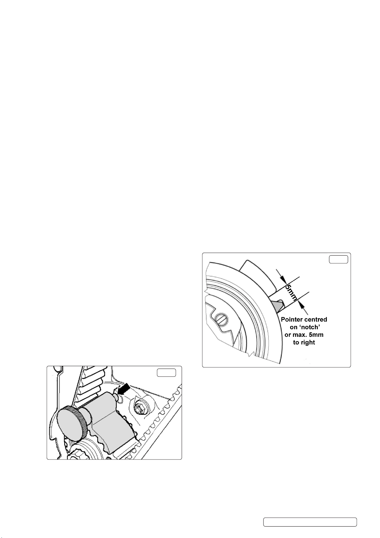
5.13.8. Once completed, all the timing tools are removed and
the engine turned over twice, by hand, returning to TDC
No.1 cylinder, and the timing tools installed to again
check the engine timing position. Check that the belt
tensioner pointer is centred (or a maximum of 5mm. to
the right) in the “notch” in the back plate (g.22).
5.13.3. The Crankshaft Locking Tool is pulled forward on the
crankshaft gear in order that it is no longer engaged
in the hole in the oil seal housing, and therefore not
‘locking’ the crankshaft (g.21).
5.13.4. The crankshaft is then turned slowly in the opposite
direction of engine rotation until the lug of the Crank
shaft Locking Tool slightly passes the hole in the oil
seal housing. The crankshaft is then turned in the
normal direction of engine rotation until the Cam
shaft Locking Pin can be inserted.
5.13.5. The 3 camshaft bolts are loosened, allowing the
sprocket to turn within the elongated holes.
The lug of the Crankshaft Locking tool will be
positioned to the right or left of the hole in the oil
seal housing
5.13.6. If to the right: slowly turn the crankshaft back
(opposite direction of engine rotation) until it passes
the hole and then turn crankshaft in the normal
direction of engine rotation and insert the lug into the
hole (and ‘lock’ the crankshaft). Using a suitable
Holding Tool counter hold the camshaft sprocket and
tighten the sprocket bolts.
5.13.7. If to the left: slowly turn the crankshaft in direction
of normal engine rotation and insert the lug into the
hole (and ‘lock’ the crankshaft). Using a suitable
Holding Tool counter hold the camshaft sprocket and
tighten the sprocket bolts.
NOTE: Always t new sprocket bolts.
Original Language Version
© Jack Sealey Limited
Original Language Version
© Jack Sealey Limited
VSE5951.V2 Issue 1 21/06/23

Sealey Group, Kempson Way, Suffolk Business Park, Bury St Edmunds, Suffolk. IP32 7AR
01284 757500 sales@sealey.co.uk www.sealey.co.uk
ENVIRONMENT PROTECTION
Recycle unwanted materials instead of disposing of them as waste. All tools, accessories and packaging should be sorted,
taken to a recycling centre and disposed of in a manner which is compatible with the environment. When the product
becomes completely unserviceable and requires disposal, drain any fluids (if applicable) into approved containers and
dispose of the product and fluids according to local regulations.
Note: It is our policy to continually improve products and as such we reserve the right to alter data, specifications and component parts without prior
notice. Please note that other versions of this product are available. If you require documentation for alternative versions, please email or call
our technical team on technical@sealey.co.uk or 01284 757505.
Important: No Liability is accepted for incorrect use of this product.
Warranty: Guarantee is 12 months from purchase date, proof of which is required for any claim.
REGISTER YOUR
PURCHASE HERE
Original Language Version
© Jack Sealey Limited
VSE5951.V2 Issue 1 21/06/23