0
SMART UNDER DESK MAGNETIC
EXERCISE BIKE
SF-B0891 SMART
USER MANUAL
DO NOT STAND ON THE UNIT!
IMPORTANT! Please retain owner’s manual for maintenance and adjustment instructions.
Your satisfaction is very important to us, PLEASE DO NOT RETURN UNTIL YOU HAVE
CONTACTED US: support@sunnyhealthfitness.com or 1- 877 - 90SUNNY (877-907-8669).

1
IMPORTANT SAFETY INFORMATION
We thank you for choosing our product. To ensure your safety and health, please use this
equipment correctly. It is important to read this entire manual before assembling and using the
equipment. Safe and effective use can only be achieved if the equipment is assembled,
maintained, and used properly. It is your responsibility to ensure that all users of the equipment
are informed of all warnings and precautions.
1. Before starting any exercise program, you should consult your physician to determine if you
have any medical or physical conditions that could put your health and safety at risk or
prevent you from using the equipment properly. Your physician’s advice is essential if you
are taking medication that affects your heart rate, blood pressure, or cholesterol level.
2. Be aware of your body’s warning signs. Incorrect or excessive exercise can be detrimental
to your health. Stop exercising if you experience any of the following symptoms: pain,
tightness in your chest, irregular heartbeat, shortness of breath, lightheartedness, dizziness,
or feelings of nausea. If you do experience any of these conditions, you should consult your
physician before continuing with your exercise program.
3. Keep children and pets away from the equipment. The equipment is designed for adult use
only.
4. Use the equipment on a solid, flat level surface with a protective cover for your floor or
carpet. To ensure safety, the equipment should have at least 2 feet (60 CM) of free space
all around it.
5. Ensure that all nuts and bolts are securely tightened before using the equipment. The
safety of the equipment can only be maintained if it is regularly examined for damage and/
or wear and tear.
6. Always use the equipment as indicated. If you find any defective components while
assembling or checking the equipment, or if you hear any unusual noises coming from the
equipment during exercise, discontinue use of the equipment immediately and do not use
until the problem has been rectified.
7. Wear suitable clothing while using the equipment. Avoid wearing loose clothing that may
become entangled in the equipment.
8. Do not place fingers or objects into the moving parts of the equipment.
9. The equipment is not suitable for therapeutic use.
10. To avoid bodily injury and/or damage to the product or property, proper lifting and moving
are required.
11. Your product is intended for use in cool, dry conditions. You should avoid storage in
extreme cold, hot or damp areas as this may lead to corrosion and other related problems.
12. This equipment is designed for indoor and home use only; it is not intended for commercial
use!
IMPORTANT NOTE: Please remove the plastic tab from the meter before use!
2
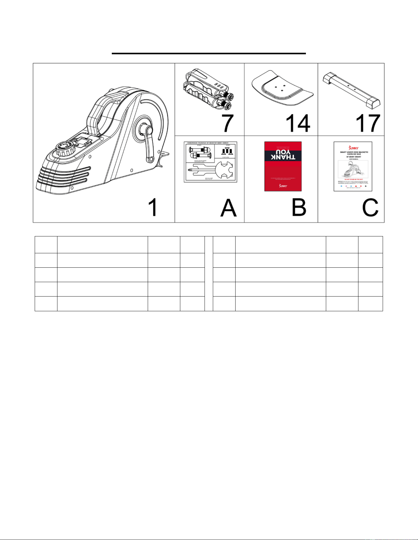
PRE-ASSEMBLY CHECK LIST
No. Description Spec. Qty.
No. Description Spec. Qty.
1 Main Frame 1 17
Front Stabilizer 1
7L
Left Pedal 1
A Hardware Package
1
7R
Right Pedal 1
B Thank You Card
1
14
Rear Fixed Bottom Plate 1
C User Manual
1
3
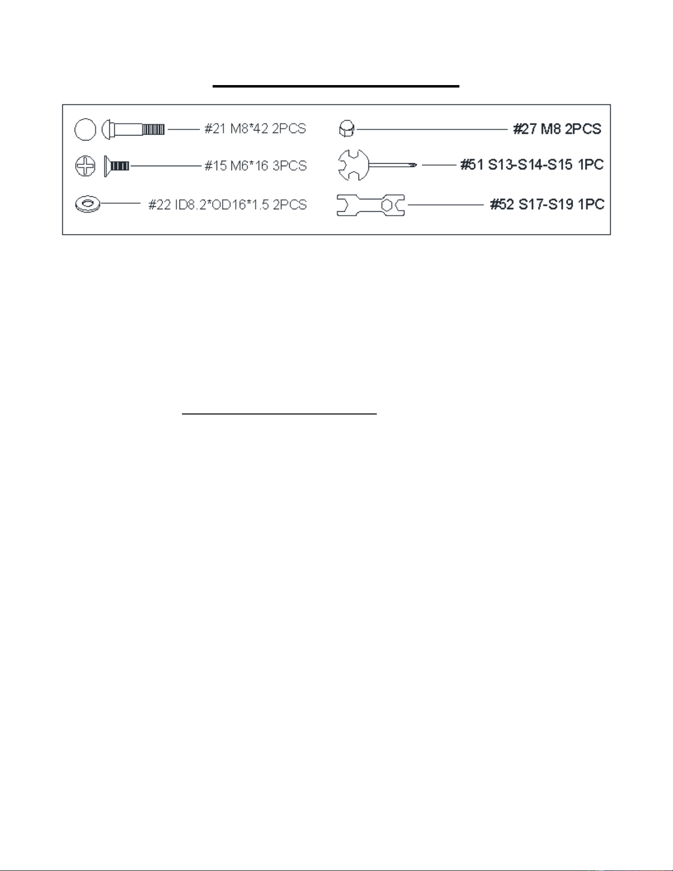
HARDWARE PACKAGE
Ordering Replacement Parts (U.S. and Canadian Customers only)
Please provide the following information in order for us to accurately identify the part(s) needed:
The model number (found on cover of manual)
The product name (found on cover of manual)
The part number found on the “EXPLODED DIAGRAM” (page 13) and “PARTS LIST”
(page 12).
Please contact us at support@sunnyhealthfitness.com or 1-877-90SUNNY (877-907-8669)
4
ASSEMBLY INSTRUCTIONS
We value your experience using Sunny Health and Fitness products. For assistance with parts
or troubleshooting, please contact us at support@sunnyhealthfitness.com or 1-877-90SUNNY
(877-907-8669).
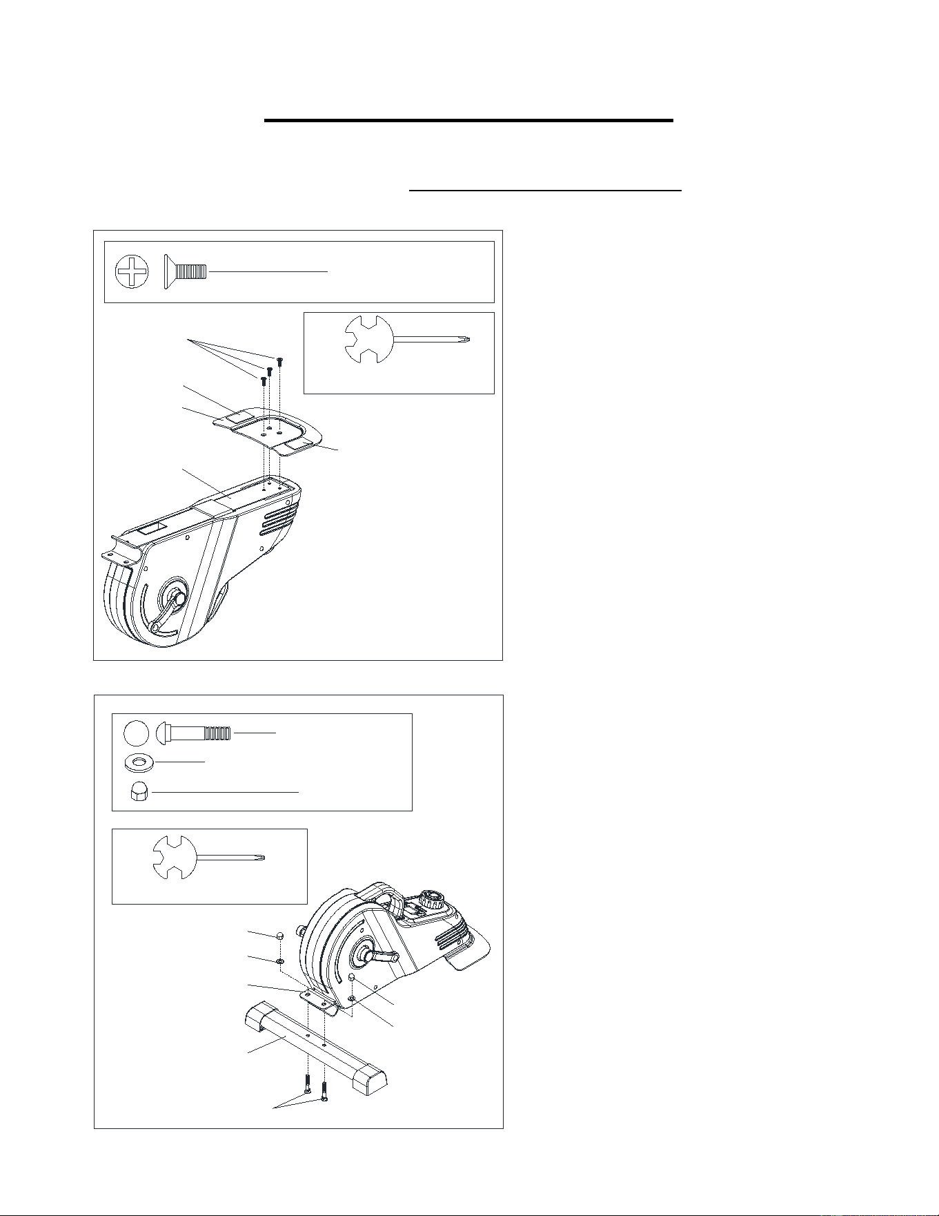
STEP 1:
Attach Rear Fixed Bottom Plate (No. 14) to
the Main Frame (No. 1) with 3 Bolts (No. 15).
Tighten and secure with Spanner (No. 51).
STEP 2:
Attach Front Stabilizer (No. 17) to the Main
Frame (No. 1) with 2 Carriage Bolts (No. 21),
2 Washers (No. 22), and 2 High Cap Nuts
(No. 27). Tighten and secure with Spanner
(No. 51).
1
15
14
49
49
#51 S13-S14-S15 1PC
#15 M6*16 3PCS
17
21
22
27
22
27
1
#22 ID8.2*OD16*1.5 2PCS
#21 M8*42 2PCS
#27 M8 2PCS
#51 S13-S14-S15 1PC
5
We value your experience using Sunny Health and Fitness products. For assistance with parts or
troubleshooting, please contact us at support@sunnyhealthfitness.com or 1-877-90SUNNY (877-
907-8669).
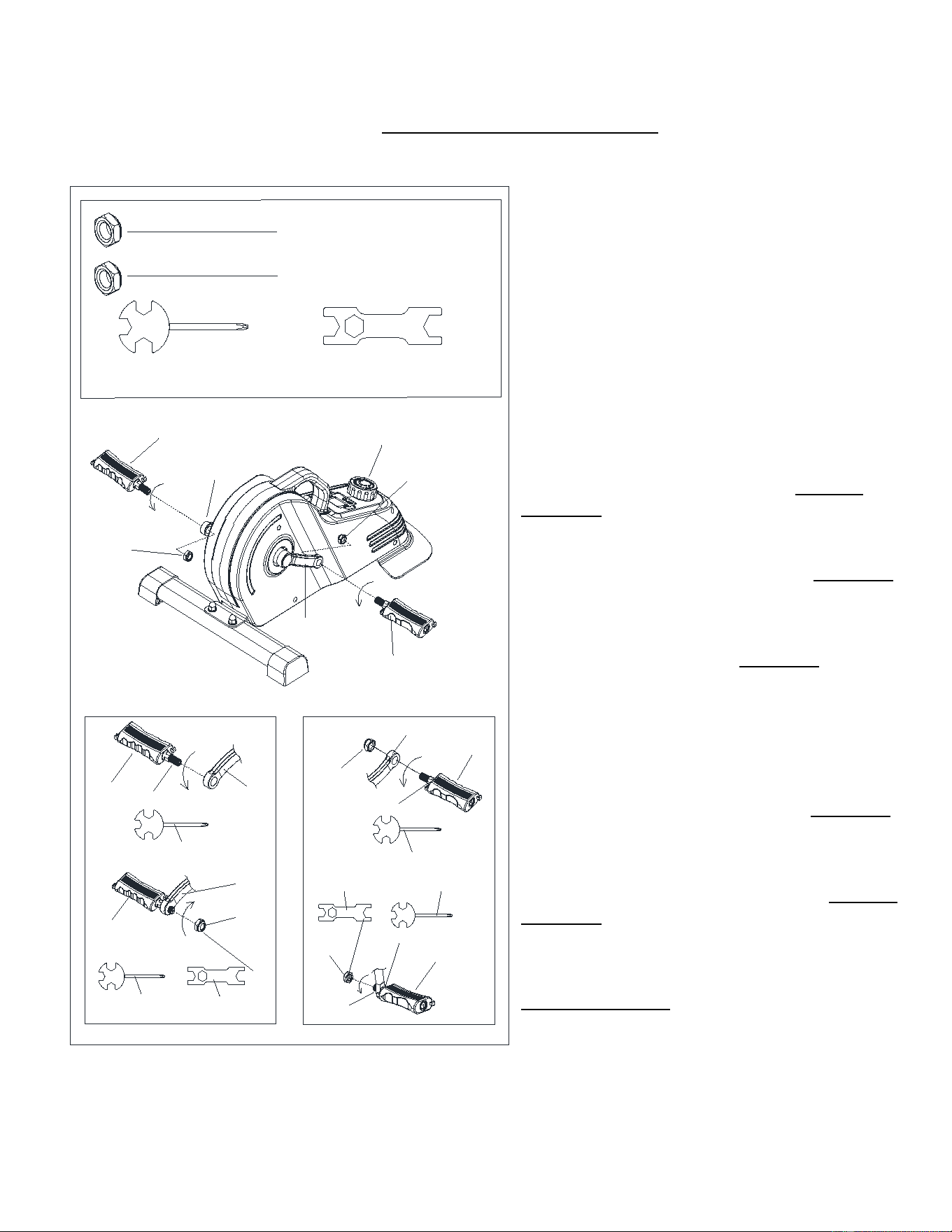
STEP 3:
NOTE: The Left & Right Pedals (No. 7L & No.
7R) are marked “L” and “R” for Left and Right.
Left Nylon Nut (No. 50L) is blue on the inside
and Right Nylon Nut (No. 50R) is white on the
inside.
Remove the 2 Left & Right Nylon Nuts (No.
50L & No. 50R) located on the Left & Right
Pedals (No. 7L & No. 7R).
Align the Left Pedal (No. 7L) with the Left
Crank (No. 3L) at 90°. Gently insert the Left
Pedal (No. 7L) into the Left Crank (No. 3L)
and turn the Left Pedal (No. 7L) counter-
clockwise as tightly as you can with your hand.
Use Spanner (No. 51) to tighten and secure.
Turn the Left Nylon Nut (No. 50L) clockwise as
tightly as you can with your hand. Use Spanner
(No. 51) to hold the pedal bolt on the Left Pedal
(No. 7L) and use Spanner (No. 52) to turn the
Left Nylon Nut (No. 50L) clockwise at the same
time, until it is tightened on to the Left Crank
(No. 3L).
Align the Right Pedal (No. 7R) with the Right
Crank (No. 3R) at 90°. Gently insert the Right
Pedal (No. 7R) into the Right Crank (No. 3R)
and turn the Right Pedal (No. 7R) clockwise as
tightly as you can with your hand. Use Spanner
(No. 51) to tighten and secure.
Turn the Right Nylon Nut (No. 50R) counter-
clockwise as tightly as you can with your hand.
Use Spanner (No. 51) to hold the pedal bolt on
the Right Pedal (No. 7R) and use Spanner (No.
52) to turn the Right Nylon Nut (No. 50R)
counter-clockwise at the same time, until it is
tightened on to the Right Crank (No. 3R).
3L
7L
3R
7R
50R
50L
9
#51 S13-S14-S15 1PC
#52 S17-S19 1PC
S19
#50R 1/2"-20 1PC
3R
7R
50R
51
3R
7R
51
52
3L
7L
50L
51
3L
7L
50L
51
52
S15
S15
S19
S15
S15
S19
#50L 1/2"-20 1PC
6
We value your experience using Sunny Health and Fitness products. For assistance with parts or
troubleshooting, please contact us at support@sunnyhealthfitness.com or 1-877-90SUNNY (877-
907-8669).
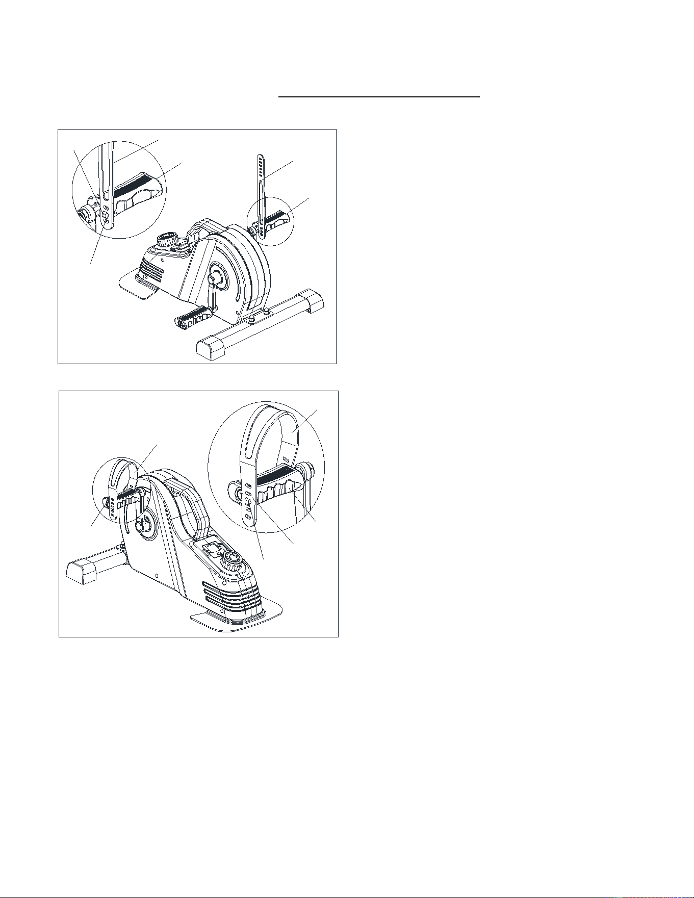
STEP 4:
Insert the fixing hole (#53-1) of the Pedal
Strap (#53) into the card slot (#7L-1) of the
Left Pedal (#7L).
Insert the fixing hole (#53-2) of the Pedal
Strap (#53) into the card slot (#7L-2) of the
Left Pedal (#7L).
53
53
7L
7L-1
53-1
7L
7L
53
53
7L
53-2
7L-2
7
We value your experience using Sunny Health and Fitness products. For assistance with parts
or troubleshooting, please contact us at support@sunnyhealthfitness.com or 1-877-90SUNNY
(877-907-8669).
7R
53
7R
53
53-1
7R-1
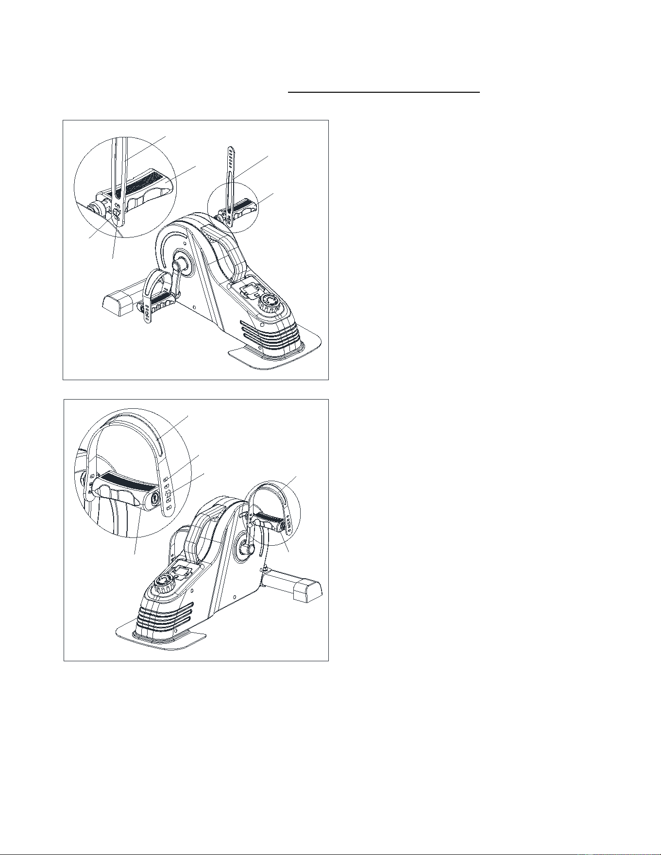
STEP 5:
Insert the fixing hole (#53-1) of the Pedal
Strap (#53) into the card slot (#7R-1) of the
Right Pedal (#7R).
Insert the fixing hole (#53-2) of the Pedal
Strap (#53) into the card slot (#7R-2) of the
Right Pedal (#7R).
NOTE
:
The position of fixing holes and card
slots can be adjusted according to the size of
your feet.
The assembly is complete!
7R
53
53
7R
53-2
7R-2
8
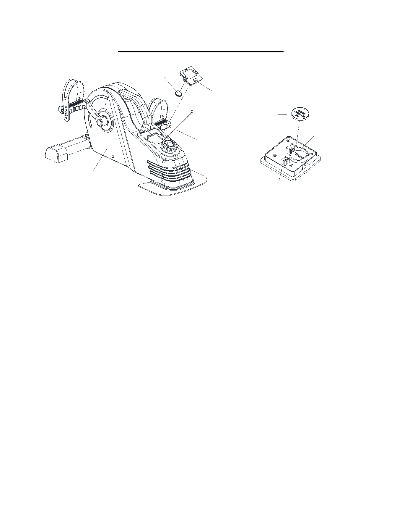
BATTERY REPLACEMENT
1. Remove the Meter (No. 10) from Main Frame (No. 1). Then disconnect the Sensor
Wire (No. 38) from the Meter (No. 10).
2. Remove the old battery from the battery seat.
3. Insert the battery and ensure that the positive side of the battery, which is labeled with a
+ sign, is facing outward as shown in diagram above.
4. Put the new battery into the battery seat.
5. Insert the Sensor Wire (No. 38) into the wire inserting hole on the back of Meter (No.
10).
6. Attach the Meter (No. 10) onto Main Frame (No. 1).
The replacement is complete!
NOTE: Dispose battery according to your state and regional guidelines.
BATTERY
(CR2032
)
BATTERY SEAT
WIRE INSERTING HOLE
10
BATTERY
38
1
9
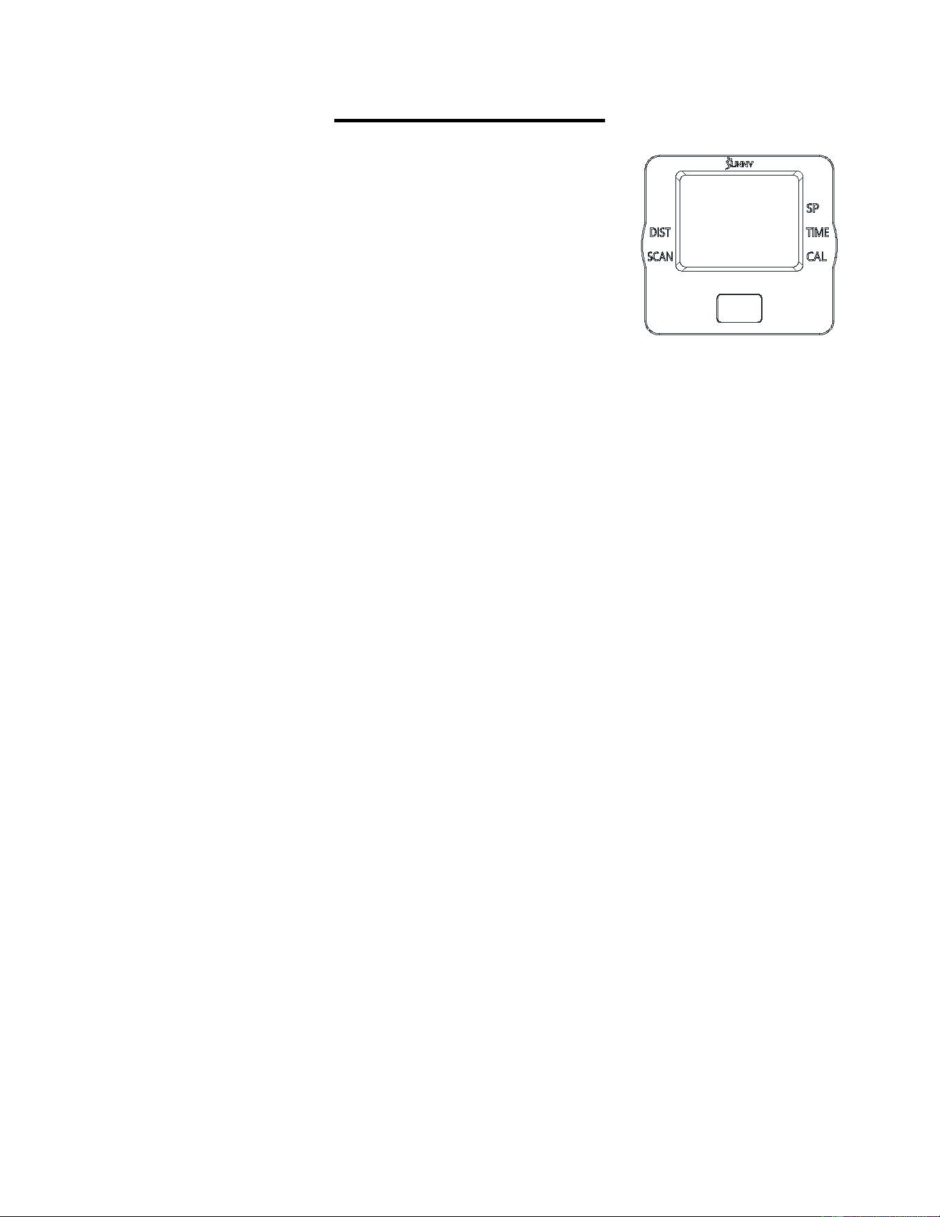
EXERCISE METER
SPECIFICATIONS:
SP(SPEED)-----------------------------------0.0~999.9 MPH (Mile/Hour)
TIME--------------------------------------------0:00~99:59 MIN
DIST (DISTANCE)--------------------------0.0~9999 M (Mile)
CAL (CALORIES)---------------------------0.0~9999 KCAL
FUNCTION KEYS:
MODE: Press the red key repeatedly to select the desired value (TIME, SP, DIST, CAL,
SCAN). Hold the key for 4 seconds to have all function values reset (total reset).
FUNCTIONS:
SP(SPEED): Displays current speed.
TIME: Counts the total time of the exercise from start to finish.
DIST (DISTANCE): Counts the distance of the exercise from start to finish.
CAL (CALORIES): Counts the total calories burned during an exercise from start to finish
SCAN: Displays functions automatically in the following order: TIME, CAL, and DIST.
NOTE:
1. Please use 1pc of 3.0V CR2032 battery as a power supply. If there is an abnormal display
on the meter, please replace the battery.
2. The meter will automatically power on when pedals are in motion or the MODE key is being
pressed.
3. The meter will automatically start calculating when exercise begins.
4. All functions will automatically stop calculating with a “STOP” sign on the upper left corner
of the meter when there is no movement for about 4 seconds; “STOP” sign will be off and
the meter will automatically start calculating as soon as the machine is in motion.
5. The meter will automatically shut off if there is no movement for 4 to 5 minutes.
10
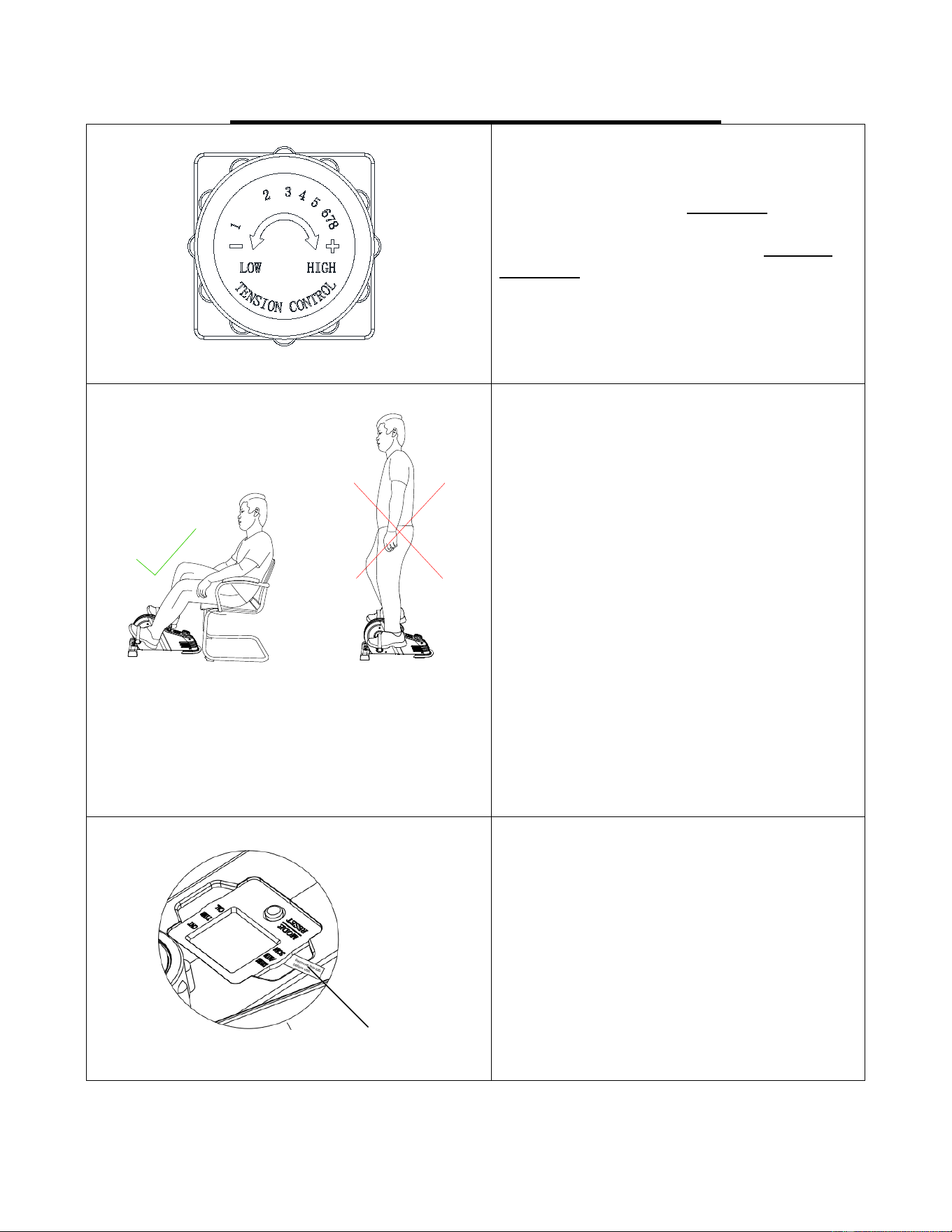
ADJUSTMENTS & USAGE GUIDE
ADJUSTING THE TENSION
Adjust the tension by rotating the Tension
Control Knob (No. 9) clockwise to
increase the level of resistance. Rotate the
Tension Control Knob (No. 9) counter-
clockwise to decrease the level of
resistance.
Tension levels are set at Level 1 being the
lowest and Level 8 being the highest.
USE ONLY WHILE SITTING.
DO NOT STAND ON THE
BIKE!
WARNING!
The bike is intended to use in a sitting
position only, do not stand on the bike.
Failure to follow all warnings and
instructions could result in serious injury or
death.
IMPORTANT NOTE:
Please remove the plastic tab from the
meter before use!
Plastic Tab
11
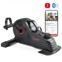
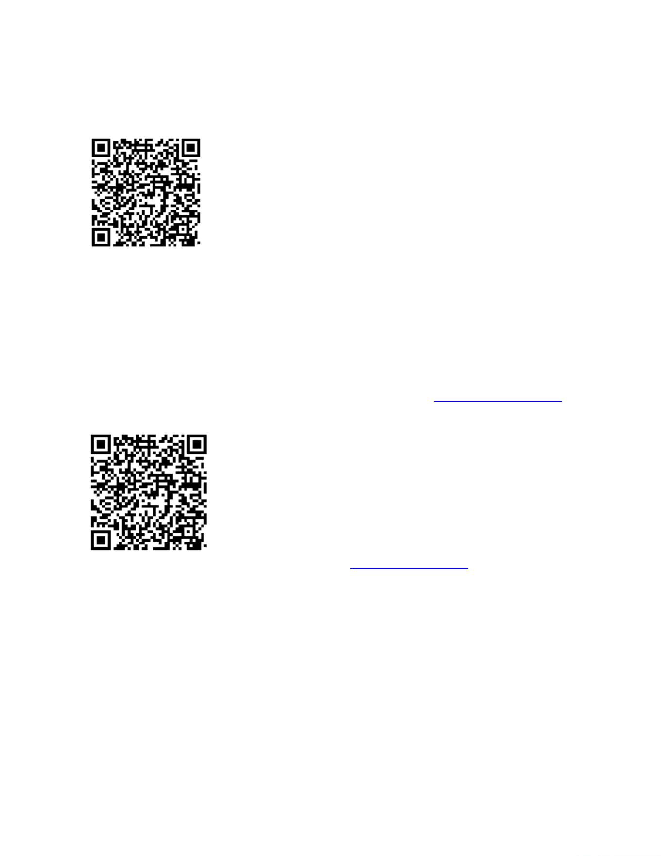
APP CONNECTION:
Connect Smart Equipment to SunnyFit App:
1. Scan to download SunnyFit from the app store:
2. Ensure that the Bluetooth function is turned on from your mobile device.
3. If this is your first time using the SunnyFit app, follow the in-app instructions to register for your
free SunnyFit account and log in.
4. Begin any workout activity that matches your smart equipment, then follow the onscreen
prompts to search for and connect to your smart equipment.
5. When connected, your stats and records will be displayed at the end of your course/session,
and recorded in your account profile!
Troubleshooting:
•
If you are having trouble connecting your smart equipment, visit www.sunnyfit.com/guide or
scan the QR code below:
•
If you require additional support, please contact [email protected].

12
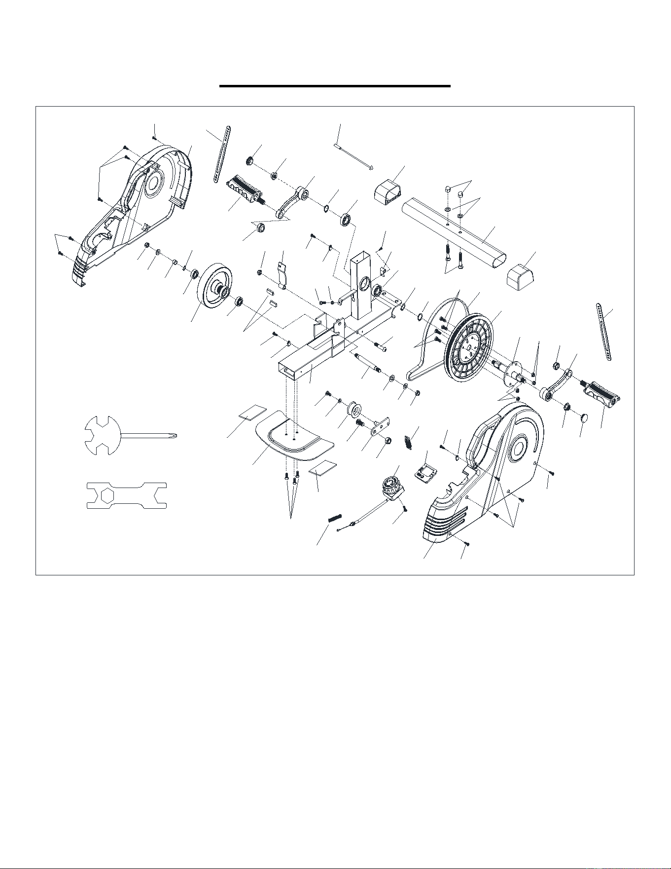
PARTS LIST
No. Description Spec. Qty
No. Description Spec. Qty
1 Main Frame 1 27 High Cap Nut M8 2
2 Spindle 1 28 Bolt M6*15 4
3L Left Crank 1 29 Nylon Nut M6 4
3R Right Crank 1 30 Belt Wheel
φ200*20
1
4 Magnetic Board 1 31 Belt J300 1
5 Idler Wheel Shaft 1 32 C-clip
φ17
2
6 Axle for Crank 1 33 Bearing 6003 2
7L Left Pedal 1 34 Screw M5*15 2
7R Right Pedal 1 35 Flat Washer
φ8.2*φ16*1.5
2
8L Left Belt Cover 1 36 Inductor Seat 1
8R Right Belt Cover 1 37 Bearing 6000 2
9 Tension Control Knob 1 38 Inductor 1
10 Meter JJD-2605 1 39 Screw M10*20*12 1
11 Inertial Wheel
φ126*28
1 40 Nylon Nut M10 1
12 Wave Washer D12 1 41 Spring
φ9.8*φ0.8*70
1
13 Idler Wheel
φ34*24
1 42 Wire Clip 3
14 Rear Fixed Bottom Plate 1 43 Screw M6*12 1
15 Bolt M6*16 3 44 Flat Washer
φ6.4*φ12*1.2
1
16 End Cap 70*60*41.5 2 45 Nut M5 1
17 Front Stabilizer 1 46 Washer
φ10.2*φ20*1.5
1
18 Sleeve
φ12*φ10.2*6
1 47 Magnet 9*20*5 2
19 Spring
φ9.8*φ0.8*70
1 48 Bolt M8*35 1
20 Screw ST3.5*15 1 49 EVA Non-slip Pad 2
21 Carriage Bolt M8*42 2 50L Left Nylon Nut 1/2"-20 1
22 Washer ID8.2*OD16*1.5 2 50R Right Nylon Nut 1/2"-20 1
23 Nylon Nut M8 3 51 Spanner S13-S14-S15 1
24 Screw ST4.2*15 14 52 Spanner S17-S19 1
25 Flange Nut M10*1.25 2 53 Pedal Strap 2
26 End Cap M22 2 54 Wave Washer D17 1
13
EXPLODED DIAGRAM
1
33
33
31
32
9
34
19
8L
8R
2
3R
3L
46
35
23
26
25
7R
29
6
30
16
17
22
27
16
24
38
14
15
40
39
13
44
43
24
37
37
35
23
26
25
32
23
4
48
21
45
34
24
24
5
7L
10
24
24
24
42
42
28
28
29
41
47
36
24
20
11
#51
49
49
12
18
50L
50R
53
53
#52
24
42
54
Version 1.0