
®
PN 2547887
May 2006 Rev. 1, 3/07
© 2006-2007 Fluke Corporation. All rights reserved. Printed in China.
All product names
are trademarks of their respective companies.
902
HVAC Clamp Meter
Users Manual
1.888.610.7664 sales@GlobalTestSupply.com
Fluke-Direct.com

LIMITED WARRANTY AND LIMITATION OF LIABILITY
This Fluke product will be free from defects in material and
workmanship for three years from the date of purchase.
This warranty does not cover fuses, disposable batteries, or
damage from accident, neglect, misuse, alteration, con-
tamination, or abnormal conditions of operation or handling.
Resellers are not authorized to extend any other warranty
on Fluke’s behalf. To obtain service during the warranty
period, contact your nearest Fluke authorized service cen-
ter to obtain return authorization information, then send the
product to that Service Center with a description of the
problem.
THIS WARRANTY IS YOUR ONLY REMEDY. NO OTHER
WARRANTIES, SUCH AS FITNESS FOR A PARTICULAR
PURPOSE, ARE EXPRESSED OR IMPLIED. FLUKE IS
NOT LIABLE FOR ANY SPECIAL, INDIRECT, INCIDEN-
TAL OR CONSEQUENTIAL DAMAGES OR LOSSES,
ARISING FROM ANY CAUSE OR THEORY. Since some
states or countries do not allow the exclusion or limitation of
an implied warranty or of incidental or consequential dam-
ages, this limitation of liability may not apply to you.
Fluke Corporation
P.O. Box 9090
Everett, WA 98206-9090
U.S.A.
Fluke Europe B.V.
P.O. Box 1186
5602 BD Eindhoven
The Netherlands
11/99
1.888.610.7664 sales@GlobalTestSupply.com
Fluke-Direct.com

i
Table of Contents
Title Page
Introduction....................................................... 1
Contacting Fluke .............................................. 2
Safety Information ............................................ 3
Symbols ........................................................... 5
Getting Acquainted with the Meter ................... 6
Using the Meter................................................ 10
AC and DC Voltage Measurement................. 10
Resistance and Continuity ............................. 11
Microamps µA Measurement ......................... 12
Temperature .................................................. 13
Capacitance................................................... 16
AC Current Measurement .............................. 16
Backlight ........................................................ 18
MIN MAX Recording Mode ............................ 18
Display HOLD ................................................ 19
Auto Off.......................................................... 19
Maintenance..................................................... 20
Cleaning the Meter......................................... 20
Battery Replacement ..................................... 21
Specifications ................................................... 23
Electrical Specifications ................................. 23
General Specifications ................................... 24
1.888.610.7664 sales@GlobalTestSupply.com
Fluke-Direct.com

902
Users Manual
ii
1.888.610.7664 sales@GlobalTestSupply.com
Fluke-Direct.com

iii
List of Tables
Table Title Page
1. 902 HVAC Clamp Meter Features.................... 7
2. Display Features .............................................. 9
List of Figures
Figure Title Page
1. 902 HVAC Clamp Meter Features.................... 6
2. Display Features .............................................. 8
3. Testing a Flame Rod ........................................ 13
4. Temperature Measurement.............................. 15
5. Proper AC Current Measurement..................... 17
6. Battery Replacement........................................ 22
1.888.610.7664 sales@GlobalTestSupply.com
Fluke-Direct.com

902
Users Manual
iv
1.888.610.7664 sales@GlobalTestSupply.com
Fluke-Direct.com

1
902
Introduction
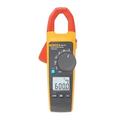
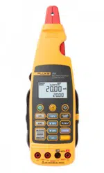
The Fluke 902 is a hand-held battery-operated HVAC
Clamp Meter (“the Meter”) that measures:
• AC current
• DC current (up to 200 µA for flame rod testing)
• AC and DC voltages
• Capacitance
• Resistance
• Continuity
• Temperature in both Celsius (°C) and Fahrenheit (°F)
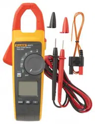
The Meter comes with:
• Two AA alkaline batteries (installed)
• Users Manual
• Soft carrying case
• TL75 Test Leads (one pair)
• 80BK Integrated DMM Temperature Probe
1.888.610.7664 sales@GlobalTestSupply.com
Fluke-Direct.com

902
Users Manual
2
Contacting Fluke
To contact Fluke, call one of the following telephone
numbers:
USA: 1-888-99-FLUKE (1-888-993-5853)
Canada: 1-800-36-FLUKE (1-800-363-5853)
Europe: +31 402-675-200
Japan: +81-3-3434-0181
Singapore: +65-738-5655
Anywhere in the world: +1-425-446-5500
Or visit Fluke’s Web site at: www.fluke.com
.
Register the Meter at: http://register.fluke.com
1.888.610.7664 sales@GlobalTestSupply.com
Fluke-Direct.com

HVAC Clamp Meter
Contacting Fluke
3
Safety Information
A “XW Warning” statement defines hazardous conditions
and actions that could cause bodily harm or death.
A “W Caution” statement identifies conditions and actions
that could damage the Meter or the equipment under test.
XWRead First: Safety Information
To ensure safe operation and service of the
Meter, follow these instructions:
• Read the Users Manual before use and
follow all safety instructions.
• Use the Meter only as specified in the
Users Manual; otherwise, the Meter's
safety features may be impaired.
• Avoid working alone so assistance can be
rendered.
• Never use the Meter on a circuit with
voltages higher than 600 V or a frequency
higher than 400 Hz fundamental. The Meter
may be damaged.
• Never measure ac current while the test
leads are inserted into the input jacks.
• Do not use the Meter or test leads if they
look damaged.
• Use extreme caution when working around
bare conductors or bus bars. Contact with
the conductor could result in electric
shock.
1.888.610.7664 sales@GlobalTestSupply.com
Fluke-Direct.com

902
Users Manual
4
• Use caution when working with voltages
above 60 V dc or 30 V ac rms or 42 V ac
peak. Such voltages pose a shock hazard.
• Clean the case with a damp cloth and mild
detergent only. Do not use abrasives or
solvents.
• To avoid false readings that can lead to
electrical shock and injury, replace the
batteries as soon as the low battery
indicator (B) appears. As the Meter gets
to the point where the low batteries affect
the readings, the Meter locks and no
measurements can be made until the
batteries are changed.
• Do not hold the Meter anywhere beyond
the tactile barrier, see Figure 1.
• Adhere to local and national safety codes.
Individual protective equipment must be
used to prevent shock and arc blast injury
where hazardous live conductors are
exposed.
1.888.610.7664 sales@GlobalTestSupply.com
Fluke-Direct.com
HVAC Clamp Meter
Symbols
5
Symbols
The following symbols are found on the Meter or in this
manual.
,
May be used on hazardous live conductors
W
Risk of danger. Important information. See Users
Manual.
X Hazardous voltage. Risk of electric shock.
T Double insulation
B
Battery
)
Complies with Canadian and US Standards
P
Conforms to relevant European Union directives
J Earth ground
F DC (Direct Current)
B AC (Alternating Current)
~
Do not dispose of this product as unsorted municipal
waste. Contact Fluke or a qualified recycler for
disposal.
;
N10140
Conforms to relevant Australian standards
s
Inspected and licensed by TÜV Product Services
1.888.610.7664 sales@GlobalTestSupply.com
Fluke-Direct.com
902
Users Manual
6
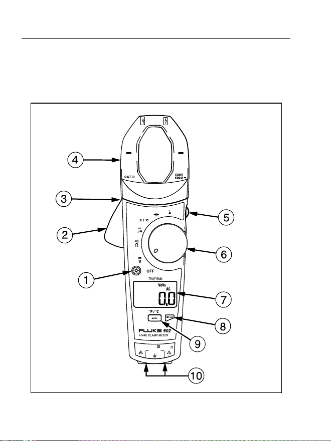
Getting Acquainted with the Meter
Refer to Figures 1 and 2 and Tables 1 and 2 to become
more acquainted with the Meter’s features.
COM
600V
CAT
V
µ
A
efu0001.eps
Figure 1. 902 HVAC Clamp Meter Features
1.888.610.7664 sales@GlobalTestSupply.com
Fluke-Direct.com
HVAC Clamp Meter
Getting Acquainted with the Meter
7
Table 1. 902 HVAC Clamp Meter Features
Number Description
A Backlight Button
B Jaw Release
C Tactile Barrier
D Jaws
E Hold Button
F Rotary Switch:
V DC and AC voltage
P Resistance and continuity
G DC microamps
F Degrees Fahrenheit / degrees Celsius
L Capacitance
K AC current
G LCD
H Min Max Button
I AC/DC, °F/°C Button
J Input Terminals
1.888.610.7664 sales@GlobalTestSupply.com
Fluke-Direct.com
902
Users Manual
8
A
B
C
D
E
F
G
efu0006.eps
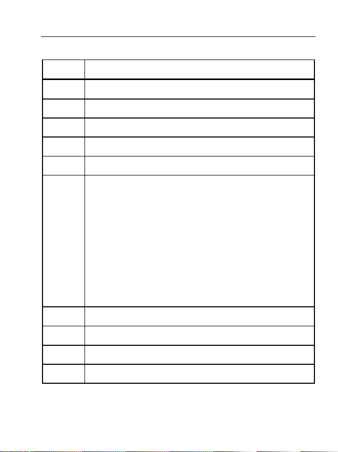
Figure 2. Display Features
1.888.610.7664 sales@GlobalTestSupply.com
Fluke-Direct.com
HVAC Clamp Meter
Getting Acquainted with the Meter
9
Table 2. Display Features
Number Indication
A
Battery indicator -The batteries are low and need to
be changed.
XWWarning: To avoid false
readings, which could lead to possible
electric shock or personal injury, replace
the batteries as soon as the battery
indicator appears.
B Indicates the presence of high voltage
C
Indicators for minimum and maximum recording
mode
D Display Hold is active
E Volts
F Amps
G
°F - Degrees Fahrenheit
°C - Degrees Celsius
e - Ohms
M - Microamps
N - Microfarads
DC - Direct Current
AC - Alternating Current
1.888.610.7664 sales@GlobalTestSupply.com
Fluke-Direct.com

902
Users Manual
10
Using the Meter
AC and DC Voltage Measurement
To measure AC or DC voltage:
1. Insert the test leads into the Meter.
2. Turn the rotary switch to V.
3. Press A to choose AC or DC voltage. The display
reflects the chosen voltage mode.
4. Use the test leads to take the measurement. The Meter
reading appears on the display.
Note
When a measured voltage is above 30 V,
Zappears on the display. When the voltage drops
below 30 V, Zdisappears.
1.888.610.7664 sales@GlobalTestSupply.com
Fluke-Direct.com

HVAC Clamp Meter
Using the Meter
11
Resistance and Continuity
To measure resistance or continuity:
XW Warning
To avoid false readings that can lead to
electrical shock and injury, de-energize the
circuit before taking the measurement.
1. Insert the test leads into the Meter.
2. Turn the rotary switch to P.
3. Take the measurement. The resistance reading
appears on the display.
• If the resistance is shorted, the Meter beeps and
shows a reading < 30 Ω.
• If the resistance is open or exceeds the Meter’s
range, the display reads OL.
1.888.610.7664 sales@GlobalTestSupply.com
Fluke-Direct.com

902
Users Manual
12
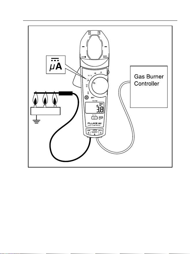
Microamps
µ
A Measurement
The µA dc (G) function on the Meter is primarily for HVAC
flame rod testing. To test a heating system flame rod (refer
to Figure 3):
1. Turn the heating unit off and locate the wire between
the gas-burner controller and the flame rod.
2. Break this connection.
3. Turn the rotary switch on the Meter to G.
4. Using alligator clips, connect test leads between the
flame sensor probe and control-module wire.
5. Turn heating unit on and check the reading on the
Meter.
6.
Refer to the heating unit documentation for what the
desired reading should be.
1.888.610.7664 sales@GlobalTestSupply.com
Fluke-Direct.com
HVAC Clamp Meter
Using the Meter
13
Burner
efu0004.eps
Figure 3. Testing a Flame Rod
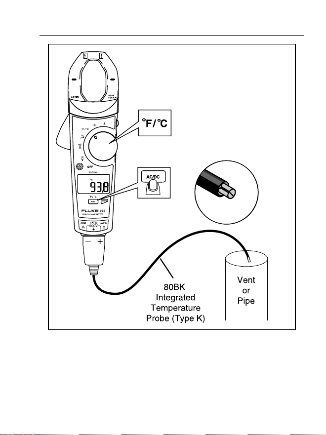
Temperature
The Meter measures temperature in either Celsius (°C) or
Fahrenheit (°F).
To measure temperature (refer to Figure 4):
1.888.610.7664 sales@GlobalTestSupply.com
Fluke-Direct.com

902
Users Manual
14
1. Connect the 80BK Integrated DMM Temperature
Probe to the input jacks noting correct polarity of the
probe.
2. Turn the rotary switch to F.
3. Press A to select °C or °F. The display reflects the
chosen temperature mode.
4. Position the probe to take the measurement. The
reading appears on the display.
Note
To meet stated accuracy, the 80BK and Meter
must be at the same temperature.
XW Warning
To avoid possible electric shock DO NOT apply
the probe tip to any conductor that is greater
than 30 V ac, 42 V peak or 60 V dc to earth.
1.888.610.7664 sales@GlobalTestSupply.com
Fluke-Direct.com
HVAC Clamp Meter
Using the Meter
15
efu0005.eps
Figure 4. Temperature Measurement
1.888.610.7664 sales@GlobalTestSupply.com
Fluke-Direct.com

902
Users Manual
16
Capacitance
Turn off circuit power, then disconnect and discharge the
capacitor before measuring capacitance. Turn the Meter’s
rotary switch to capacitance (L).
If the capacitor requires more discharging, diSC is
displayed while the capacitor discharges. When measuring,
be sure to note the correct polarity of the capacitor.
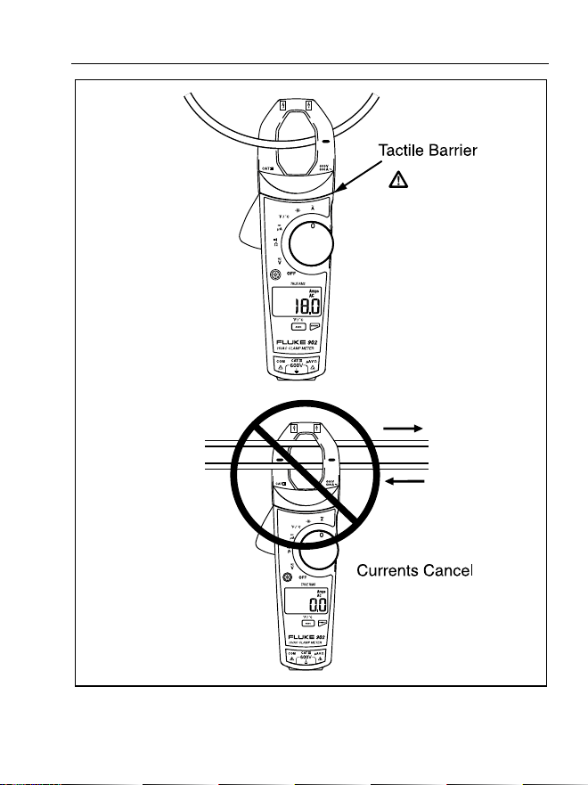
AC Current Measurement
XW Warning
To avoid electrical shock and injury:
• Remove Test Leads before making current
measurements.
• Do not hold the Meter anywhere beyond
the tactile barrier, see Figure 1.
Turn the rotary switch to AC current (K). When measuring
AC current, it is necessary that the measured wire be
properly seated within the clamp jaws. The wire being
measured should be centered within the jaws, below the
horizontal line located on the clamp. Also note that currents
moving in different directions will cancel each other out, so
one wire must be measured at a time for a correct
measurement (see Figure 5).
1.888.610.7664 sales@GlobalTestSupply.com
Fluke-Direct.com
HVAC Clamp Meter
Using the Meter
17
efu0003.eps
Figure 5. Proper AC Current Measurement
1.888.610.7664 sales@GlobalTestSupply.com
Fluke-Direct.com

902
Users Manual
18
Backlight
Press C to toggle the backlight on and off. The backlight
automatically turns off after 2 minutes.
To disable the automatic 2-minute backlight timeout, hold
down
Cwhile turning the Meter on.
MIN MAX Recording Mode
The MIN MAX recording mode captures the minimum and
maximum input values. When a new high or low is
detected, the Meter beeps.
To use this feature:
1. Put the Meter into the desired measurement function
and range.
2. Press Jto enter MIN MAX Mode. MAX is displayed
and the highest reading detected since entering MIN
MAX is displayed.
3. Press Jto step through the minimum (MIN) and
present readings.
4. To pause MIN MAX recording without erasing stored
values, press I. K is displayed.
5. To resume MIN MAX recording, press I again.
6. To exit and erase stored readings, press Jfor at
least two seconds.
1.888.610.7664 sales@GlobalTestSupply.com
Fluke-Direct.com

HVAC Clamp Meter
Using the Meter
19
Display HOLD
XWWarning
To avoid possible electric shock or personal
injury, when Display HOLD is activated, be
aware that the display will not change when
you apply a different voltage.
In the Display HOLD mode, the Meter freezes the display.
The Meter also beeps every 4 seconds and Hflashes
to remind the user.
Press Ito activate Display HOLD; His displayed and
the reading is captured.
To exit and return to normal operation, press I.
Auto Off
The Meter automatically turns off after 20 minutes. The
rotary switch must be turned to “OFF” and then turned back
on for the Meter to restart. Auto Off is disabled during Min
Max mode. To disable Auto Off, hold J when turning
the Meter on.
1.888.610.7664 sales@GlobalTestSupply.com
Fluke-Direct.com

902
Users Manual
20
Maintenance
XWWarning
To avoid possible electric shock or personal
injury, repairs or servicing not covered in this
manual should be performed only by qualified
personnel.
Cleaning the Meter
XWWarning
To avoid electrical shock, remove any input
signals before cleaning.
W Caution
To avoid damaging the Meter, do not use
aromatic hydrocarbons or chlorinated solvents
for cleaning. These solutions will react with the
plastics used in the Meter.
Clean the instrument case with a damp cloth and mild
detergent.
1.888.610.7664 sales@GlobalTestSupply.com
Fluke-Direct.com

HVAC Clamp Meter
Maintenance
21
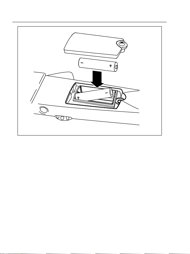
Battery Replacement
XWWarning
To avoid false readings that could lead to
possible electric shock or personal injury,
replace the batteries as soon as the low
battery indicator (B) appears.
Disconnect the test leads before replacing the
batteries.
To replace the batteries (refer to Figure 6):
1. Turn the rotary switch to “OFF” and remove the test
leads from the terminals.
2. Use a Phillips screwdriver to loosen the battery
compartment door screw, and remove the door from
the case bottom.
3. Remove the batteries.
4. Replace the batteries with two new AA batteries.
5. Reattach the battery compartment door to the case
bottom and tighten the screw.
1.888.610.7664 sales@GlobalTestSupply.com
Fluke-Direct.com
902
Users Manual
22
efu0002.eps
Figure 6. Battery Replacement
1.888.610.7664 sales@GlobalTestSupply.com
Fluke-Direct.com

HVAC Clamp Meter
Specifications
23
Specifications
Electrical Specifications
Function Range Resolution Accuracy
Voltage DC 0 – 600 V 0.1 V 1 % ± 5 counts
Voltage AC
(True Rms)
0 – 600 V 0.1 V
1 % ± 5 counts
(50/60 Hz)
Current AC
(True Rms)
0 – 600 A 0.1 A
2.0 % ± 5 counts
(50/60 Hz)
Current DC 0 - 200 µA 0.1 µA 1.0 % ± 5 counts
Resistance
0 – 999 Ω
0 – 9999 Ω
0.1 Ω
1.0 Ω
1.5 % ± 5 counts
Continuity < 30 Ω
Temperature -10 to 400 °C 0.1 °C 1 % ± 0.8 °C
Capacitance
1-100 µF
100-1000 µF
0.1 µF
1 µF
1.9 % ± 2 counts
1.888.610.7664 sales@GlobalTestSupply.com
Fluke-Direct.com

902
Users Manual
24
General Specifications
Operating Temperature -10 °C to +50 °C
Storage Temperature -40 °C to +60 °C
Operating Humidity Non condensing (< 10 °C)
90 % RH (10 °C to 30 °C)
75 % RH (30 °C to 40 °C)
45 % RH (40 °C to 50 °C)
(Without Condensation)
Operating Altitude 2500 meters above mean sea
level
Storage Altitude 12,000 meters above mean
sea level
IP Rating IP 30 per IEC 60529
Vibration Requirements MIL-PRF-28800F Class 2
random vibration
EMI, RFI, EMC EMI: instrument unspecified for
use in EMC field • 0.5 V /
Meter
EMC: Meets all applicable
requirements in EN61326-1
Temperature
Coefficients
0.1 x (specified accuracy)/ °C
(<18 °C or >28 °C)
1.888.610.7664 sales@GlobalTestSupply.com
Fluke-Direct.com

HVAC Clamp Meter
Specifications
25
Size (H X W X L) 9.1 x 3.8 x 1.7 inches
(240 x 80 x 40 mm)
Weight 1.1 lb
(310 g)
Design Standards and
Compliance
IEC 61010, IEC 61010-2-
032,CE
Agency Approvals
P )
; s
N10140
Over-voltage Category 600 V, CAT III per IEC 1010-1
CAT III equipment is designed
to protect against transients in
equipment in fixed-equipment
installations, such as
distribution panels, feeders
and short branch circuits, and
lighting systems in large
buildings.
Power Requirements Two AA Batteries, NEDA 15 A,
IEC LR6
1.888.610.7664 sales@GlobalTestSupply.com
Fluke-Direct.com

902
Users Manual
26
1.888.610.7664 sales@GlobalTestSupply.com
Fluke-Direct.com