
®
345
Power Quality Clamp Meter
Users Manual
PN 2560401
October 2006
© 2006 Fluke Corporation, All rights reserved. Printed in China
Product names are trademarks of their respective companies.
1.888.610.7664 sales@GlobalTestSupply.com
Fluke-Direct.com

LIMITED WARRANTY AND LIMITATION OF LIABILITY
Each Fluke product is warranted to be free from defects in material and workmanship under normal
use and service. The warranty period is one year and begins on the date of shipment. Parts, product
repairs, and services are warranted for 90 days. This warranty extends only to the original buyer or
end-user customer of a Fluke authorized reseller, and does not apply to fuses, disposable batteries, or
to any product which, in Fluke's opinion, has been misused, altered, neglected, contaminated, or
damaged by accident or abnormal conditions of operation or handling. Fluke warrants that software
will operate substantially in accordance with its functional specifications for 90 days and that it has
been properly recorded on non-defective media. Fluke does not warrant that software will be error free
or operate without interruption.
Fluke authorized resellers shall extend this warranty on new and unused products to end-user cus-
tomers only but have no authority to extend a greater or different warranty on behalf of Fluke. War-
ranty support is available only if product is purchased through a Fluke authorized sales outlet or Buyer
has paid the applicable international price. Fluke reserves the right to invoice Buyer for importation
costs of repair/replacement parts when product purchased in one country is submitted for repair in
another country.
Fluke's warranty obligation is limited, at Fluke's option, to refund of the purchase price, free of charge
repair, or replacement of a defective product which is returned to a Fluke authorized service center
within the warranty period.
To obtain warranty service, contact your nearest Fluke authorized service center to obtain return au-
thorization information, then send the product to that service center, with a description of the difficulty,
postage and insurance prepaid (FOB Destination). Fluke assumes no risk for damage in transit. Fol-
lowing warranty repair, the product will be returned to Buyer, transportation prepaid (FOB Destination).
If Fluke determines that failure was caused by neglect, misuse, contamination, alteration, accident, or
abnormal condition of operation or handling, including overvoltage failures caused by use outside the
product’s specified rating, or normal wear and tear of mechanical components, Fluke will provide an
estimate of repair costs and obtain authorization before commencing the work. Following repair, the
product will be returned to the Buyer transportation prepaid and the Buyer will be billed for the repair
and return transportation charges (FOB Shipping Point).
THIS WARRANTY IS BUYER'S SOLE AND EXCLUSIVE REMEDY AND IS IN LIEU OF ALL OTHER
WARRANTIES, EXPRESS OR IMPLIED, INCLUDING BUT NOT LIMITED TO ANY IMPLIED WAR-
RANTY OF MERCHANTABILITY OR FITNESS FOR A PARTICULAR PURPOSE. FLUKE SHALL
NOT BE LIABLE FOR ANY SPECIAL, INDIRECT, INCIDENTAL, OR CONSEQUENTIAL DAMAGES
OR LOSSES, INCLUDING LOSS OF DATA, ARISING FROM ANY CAUSE OR THEORY.
Since some countries or states do not allow limitation of the term of an implied warranty, or exclusion
or limitation of incidental or consequential damages, the limitations and exclusions of this warranty
may not apply to every buyer. If any provision of this Warranty is held invalid or unenforceable by a
court or other decision-maker of competent jurisdiction, such holding will not affect the validity or en-
forceability of any other provision.
11/99
1.888.610.7664 sales@GlobalTestSupply.com
Fluke-Direct.com

i
Table of Contents
Title Page
Introduction .......................................................................................... 1
Symbols ................................................................................................ 1
Safety Instructions ................................................................................ 2
Specifications........................................................................................ 4
Electrical Data .................................................................................. 4
General Data ..................................................................................... 11
Qualified Personnel............................................................................... 12
Safe Operation ...................................................................................... 12
Proper Usage......................................................................................... 12
Warranty ............................................................................................... 13
Electrical Connections .......................................................................... 13
Accessories ........................................................................................... 13
Risks During Clamp Meter Operation .................................................. 13
Device Shutdown.................................................................................. 14
Maintenance and Repairs...................................................................... 14
Measuring Inputs and Power Adapter................................................... 15
Voltage Measuring Input .................................................................. 15
Power Adapter and USB Connection................................................ 15
Design and Functions............................................................................ 16
Front View........................................................................................ 17
Rear and Side View .......................................................................... 18
Using the Clamp Meter......................................................................... 19
Check the Shipment.......................................................................... 19
Preparing Clamp Meter for Use ........................................................ 19
Initial Setup................................................................................... 19
Switching the Clamp Meter On..................................................... 20
Switching the Device Off.............................................................. 21
Connection to Circuits .......................................................................... 21
Connecting Sequence........................................................................ 21
Overview....................................................................................... 22
Voltage and Current Measurements.............................................. 22
Single Phase Power Measurement Connection............................. 24
Balanced Three-Phase Power Measurement Connection.............. 25
Configuration........................................................................................ 26
Operating Controls and Display........................................................ 26
1.888.610.7664 sales@GlobalTestSupply.com
Fluke-Direct.com

345
Users Manual
ii
Display Symbols .............................................................................. 27
Navigation and Measuring Keys ...................................................... 28
Navigation through the Display........................................................ 28
Measurement Setup .............................................................................. 29
Basic Adjustments Required before Measuring ............................... 29
Voltage Range Settings ................................................................ 30
Current Range Settings................................................................. 31
Additional Instrument Settings..................................................... 31
Measurements ...................................................................................... 33
Measurement Tips ............................................................................ 33
Displaying Measurements ............................................................ 33
Saving Measurement Screens....................................................... 34
Viewing Saved Screens ................................................................ 35
Logging Tips .................................................................................... 36
Measurement Function Overview ........................................................ 42
Voltage Measurements ..................................................................... 42
Current Measurement ....................................................................... 45
D Waveforms ............................................................................... 45
L Harmonics ................................................................................ 47
Harmonic Recording .................................................................... 51
WPower ........................................................................................... 54
X Three-Phase Power................................................................. 57
I Current ............................................................................. 58
I Recording Playback ......................................................... 64
1.888.610.7664 sales@GlobalTestSupply.com
Fluke-Direct.com

iii
List of Tables
Table Title Page
1. Symbols ................................................................................................ 1
2. Navigation and Measuring Keys........................................................... 28
3. Voltage Measurements ......................................................................... 43
4. Current Measurements.......................................................................... 45
5. Waveforms Measurements.................................................................... 45
6. Harmonics Measurements..................................................................... 48
7. Power.................................................................................................... 54
8. Three Phase Power................................................................................ 57
1.888.610.7664 sales@GlobalTestSupply.com
Fluke-Direct.com

v
List of Figures
Figure Title Page
1. Voltage Measuring Input ...................................................................... 15
2. Slider Switch for Line Power Voltage (115 V and 230 V) ................... 15
3. Power Adapter and USB Connection.................................................... 16
4. 345 Front View ..................................................................................... 17
5. Rear and Side View .............................................................................. 18
6. Battery Life Screen of Clamp Meter..................................................... 20
7. Voltage and Current Measurement Connections................................... 23
8. Single Phase Power Measurement Connection..................................... 24
9. Three-Phase Power Connection............................................................ 26
10. Display Symbols of Clamp Meter......................................................... 27
11. Navigation through the Display ............................................................ 29
12. Voltage Range Settings......................................................................... 30
13. Current Range Settings ......................................................................... 31
14. Additional Instrument Settings Menu ................................................... 32
15. Additional Instrument Setting Items ..................................................... 33
16. Detailed View of Harmonic Recording Display ................................... 53
1.888.610.7664 sales@GlobalTestSupply.com
Fluke-Direct.com
1
345 Power Quality Clamp Meter
Introduction
The Fluke 345 Power Quality Clamp Meter, referred throughout this document
simply as the “Clamp Meter”, is a rugged, accurate, professional power
industry tool for measuring current, voltage, and power quality.
Symbols
Table 1 lists the symbols used on the instrument and/or in this manual.
Table 1. Symbols
Symbol Description
X
Hazardous voltage. Risk of electrical shock.
W
Important information. Risk of danger. See manual
J
Earth ground
~
Do no dispose of this product as municipal waste.
Contact Fluke or a qualified recycler for disposal
T
Double insulated.
M
Low battery when shown on display.
F
DC (Direct Current).
CAT
IEC 61010 Measurement (installation) Category .
P
Conforms to requirements of European Union and
European Free Trade Association (EFTA).
)
Canadian Standards Association.
;
N10140
Conforms to relevant Australian standards.
1.888.610.7664 sales@GlobalTestSupply.com
Fluke-Direct.com

345
Users Manual
2
Safety Instructions
Please read this section carefully. It will familiarize you with important safety
instructions for handling your Clamp Meter. In this manual a
Warning
identifies conditions and actions that pose hazard(s) to the user. A Caution
identifies conditions and actions that may damage the test instrument.
The design and manufacture of the device conforms to the latest state of
technology and the safety standards specified in IEC 61010-1/ 2
nd
edition. If
used improperly, there is a risk of damage to persons and property.
W X Warning
Review the entire manual before using the Clamp Meter
and its accessories. To avoid electrical shock or fire:
• Use the Meter only as specified in this manual or the
protection provided by the Meter might be impaired.
• Use caution when working with voltages above 33 V
acrms, 46.7 V ac peak, or 70 V dc. These voltages pose
ashock hazard.
• When using probes, keep your fingers behind the
finger guards.
• Replace the battery as soon as the low battery
• indicator (
B) appears to avoid false readings that can
lead to electric shock and injury.
• Adhere to local and national safety codes. Individual
protective equipment must be used to prevent shock
and arc blast injury where hazardous live conductors
are exposed.
• Do not hold the Current Probe anywhere beyond the
tactile barrier, see Figure 4.
1.888.610.7664 sales@GlobalTestSupply.com
Fluke-Direct.com

Power Quality Clamp Meter
Safety Instructions
3
• Before use, inspect the Clamp Meter, voltage probes,
test leads, and accessories for mechanical damage,
and replace if damaged. Look for cracks or missing
plastic. Pay special attention to the insulation
surrounding the connectors.
• Avoid working alone when working with live circuits.
• Use only insulated test leads and adapters as supplied
with the Clamp Meter, or indicated as suitable for the
Fluke 345 Clamp Meter.
• Always connect the Battery Charger/Power Adapter
first to the ac outlet before connecting it to the Clamp
Meter.
• Remove all probes, test leads and accessories not in
use.
• Do not operate the Clamp Meter around explosive gas
or vapor.
• Do not exceed Clamp Meter input voltage or current
ratings.
• Do not use exposed metal BNC or banana plug
connectors or insert metal objects into connectors.
WCaution
Do not open the Clamp Meter for cleaning. Do not use
solvents to clean it, and do not immerse it in liquid.
Only trained personnel should perform maintenance work.
Any such work undertaken by unauthorized personnel may
damage the Clamp Meter and will invalidate the warranty.
1.888.610.7664 sales@GlobalTestSupply.com
Fluke-Direct.com

345
Users Manual
4
Specifications
Electrical Data
All accuracies specified at 23 °C ± 1 °C
Temperature coefficient of current ≤ ±0.15 % of rdg per °C
Temperature coefficient of voltage ≤ ±0.15 % of rdg per °C
Current Measurement (DC, DC RMS, AC RMS)
Measuring range................................................. 0 – 2000 A dc, 1400 ac rms
Autorange facility ................................................ 40 A / 400 A / 2000 A
Resolution........................................................... 10 mA in 40 A range
100 mA in 400 A range
1 A in 2000 A range
Accuracy
RMS and DC
I > 10 A ........................................................... ± 1.5 % rdg ± 5 digits
I < 10 A ........................................................... ± 0.2 A
AVE
I > 10 A ........................................................... ± 3 % rdg ± 5 digits
I < 10 A ........................................................... ± 0.5 A
Pk
I > 10 A ........................................................... ± 5 % rdg ± 5 digits
I < 10 A ........................................................... ± 0.5 A
AHr
I > 10 AHr ....................................................... ± 2 % rdg ± 5 digits
I < 10 AHr ....................................................... ± 0.5 AHr
CF (Crest Factor)
1.1 ≤ CF < 3.................................................... ± 3 % rdg ± 5 digits
3 ≤ CF < 5....................................................... ± 5 % rdg ± 5 digits
Resolution....................................................... 0.01
RPL (Ripple)
2 % ≤ RPL< 100 % ......................................... ± 3 % rdg ± 5 digits
100 % ≤ RPL< 600 % ..................................... ± 5 % rdg ± 5 digits
Resolution....................................................... 0.1 %
I
DC
> 5 A, I
AC
> 2 A
All measurements DC and 15 Hz to 1 kHz.
Maximum overload 10,000 A or rms x frequency < 400,000.
Amps rms is a true rms measurement (ac + dc)
1.888.610.7664 sales@GlobalTestSupply.com
Fluke-Direct.com

Power Quality Clamp Meter
Specifications
5
Harmonics
THD (Total Harmonic Distortion)
1 % ≤ THD 1 % to 100 %:............................... ± 3 % rdg ± 5 digits
100 % to 600 %: ............................................. ± 5 % rdg ± 5 digits
Resolution....................................................... 0.1 %
DF (Distortion Factor)
1 % ≤ DF < 100 % ......................................... ± 3 % rdg ± 5 digits
Resolution....................................................... 0.1 %
H02 ≤ I
harm
< H13............................................. ± 5 % rdg ± 2 digits
H13 ≤ I
harm
≤ H30............................................ ± 10 % rdg ± 2 digits
All measurements up to 30
th
harmonic (40th harmonic for 15 Hz to 22 Hz)
Frequency range of fundamental F
0
15 Hz to 22 Hz and 45 Hz to 65 Hz
I
acrms
> 10 A
Voltage Measurement (DC, DCRMS, ACRMS)
Measuring range................................................. 0 – 825 V dc or ac rms
Autorange facility ................................................ 4V / 40V / 400V / 750V
Resolution........................................................... 1 mV in 4 V range
10 mV in 40 V range
100 mV in 400 V range
1 V in 750 V range
Accuracy
RMS and DC
V > 1 V............................................................ ± 1 % rdg ± 5 digits
V < 1 V............................................................ ± 0.02 V
AV
V > 1 V............................................................ ± 3 % rdg ± 5 digits
V < 1 V............................................................ ± 0.03 V
Pk
V > 1 V............................................................ ± 5 % rdg ± 5 digits
V < 1 V............................................................ ± 0.03 V
CF (Crest Factor)
1.1 ≤ CF < 3.................................................... ± 3 % rdg ± 5 digits
3 ≤ CF < 5....................................................... ± 5 % rdg ± 5 digits
Resolution....................................................... 0.01
RPL (Ripple)
2 % ≤ RPL< 100 % ......................................... ± 3 % rdg ± 5 digits
100 % ≤ RPL< 600 % ..................................... ± 5 % rdg ± 5 digits
Resolution....................................................... 0.1 %
V
DC
> 0.5 V, V
AC
> 0.2 V
All measurements DC and 15 Hz to 1 kHz.
Maximum overload 825 V rms
Volts rms is a true rms measurement (ac + dc)
1.888.610.7664 sales@GlobalTestSupply.com
Fluke-Direct.com

345
Users Manual
6
Harmonics
THD (Total Harmonic Distortion)
1 % ≤ THD < 100 %........................................ ± 3 % rdg ± 5 digits
100 % ≤ THD < 600 %.................................... ± 5 % rdg ± 5 digits
Resolution....................................................... 0.1 %
DF (Distortion Factor)
1 % ≤ DF < 100 % .......................................... ± 3 % rdg ± 5 digits
Resolution....................................................... 0.1 %
H02 ≤ V
harm
< H13 ........................................... ± 5 % rdg ± 2 digits
H13 ≤ V
harm
≤ H30 .......................................... ± 10 % rdg ± 2 digits
All measurements up to 30
th
harmonic (40th harmonic for 15 Hz to 22 Hz)
Frequency range of fundamental F
0
15 Hz to 22 Hz and 45 Hz to 65 Hz
V
acrms
> 1V
Watts Measurement (Single and 3 Phase) (DC, DC RMS, AC RMS)
Measuring range............................................. 0 – 1650 kW dc or 1200 kW ac
Autoranging facility ......................................... 4 kW, 40 kW, 400 kW, 1650 kW
Resolution....................................................... 1 W in 4 kW
10 W in 40 kW
100 W in 400 kW
1 kW in 1650 kW
Accuracy......................................................... 2.5 % rdg ± 5 digits
W1Ø < 2 kW ± 0.08 kW
W3Ø < 4 kW ± 0.25 kW
VA Measurement (Single and 3 Phase) (DC, DC RMS, AC RMS)
Measuring range................................................. 0 to 1650 kVA dc or 1200 kVA ac
Autorange facility ................................................ 4 kVA, 40 kVA, 400 kVA, 1650 kVA
Resolution........................................................... 1 VA in 4 kVA
10 VA in 40 kVA
100 VA in 400 kVA
1 kVA in 1650 kVA
Accuracy
VA > 2 kVA ..................................................... 2.5 % rdg ± 5 digits
VA < 2 kVA ..................................................... ± 0.08 kVA
1.888.610.7664 sales@GlobalTestSupply.com
Fluke-Direct.com

Power Quality Clamp Meter
Specifications
7
VAR Measurement (Single and 3 Phase)
Measuring range................................................. 0 – 1200 kVAR
Autorange facility ................................................ 4 kVAR, 40 kVAR, 400 kVAR, 1200
kVAR
Resolution........................................................... 1 VAR in 4 kVAR range
10 VAR in 40 kVAR range
100 VAR in 400 kVAR range
1 kVAR in 1200 kVAR range
Accuracy
VAR > 4 kVAR ................................................ ± 2.5 % rdg ± 5 digits
VAR < 4 kVAR ................................................ ± 0.25 kVAR
Power Factor range ............................................ 0.3 < PF < 0.99
Power Factor (Single and 3 Phase)
Power Factor
Measuring range ............................................ 0.3 cap … 1.0 … 0.3 ind
(72.5° capacitive ... 0° ... 72.5°
inductive)
Resolution....................................................... 0.001
Accuracy ......................................................... ± 3 °
Frequency range 15 Hz to 1 kHz
Displacement Power Factor
Measuring range ............................................ 0.3 cap … 1.0 … 0.3 ind
(72.5 ° capacitive ... 0° ... 72.5 °
inductive)
Resolution....................................................... 0.001
Accuracy ......................................................... ± 3 °
Frequency ranges .......................................... 15 Hz to 22 Hz and 45 Hz to 65 Hz
Kilowatt Hour (kWHr)
Measuring range................................................. 40,000 kWHr
Autorange facility ................................................ 4 kWHr, 40 kWHr, 400 kWHr, 4,000
kWHr, 40,000 kWHr
Resolution........................................................... 1 WHr in 4 kWHr range
10 WHr in 40 kWHr range
100 WHr in 400 kWHr range
1 kWHr in 4,000 kWHr range
10 kWHr in 40,000 kWHr range
1.888.610.7664 sales@GlobalTestSupply.com
Fluke-Direct.com

345
Users Manual
8
Accuracy
kWHr > 2 kWHr .............................................. ± 3 % ± 5 digits
kWHr < 2 kWHr .............................................. ± 0.08 kWHr
All Watts /VA /VAR /PF measurements
Frequency range ............................................ DC and 15 Hz to 1 kHz
Current range ................................................. 10 A to 1400 A rms
Voltage range ................................................. 1 V to 825 V rms
Maximum input ............................................... 825 V rms / 1400 A rms
Maximum overload ......................................... 825 V rms / 10,000 A All
measurements DC and 15 Hz to 1
kHz. Maximum overload 10,000 A or
rms x frequency < 400,000.
Frequency Measurement (From Current or Voltage sources)
Measuring range................................................. 15 Hz to 1 kHz
Resolution........................................................... 0.1 Hz
Accuracy
15 to 22 Hz .................................................... ± 0.5 % rdg
40 to 70 Hz ..................................................... ± 0.5 % rdg
15 to 1000 Hz ................................................. ± 1 % rdg
Current Range .................................................... 10 A to 1400 A rms
Voltage Range.................................................... 1 V to 825 V rms
Scope Function
Current measurement
Ranges ........................................................... 10 A/20 A/40 A/100 A/200 A/400
A/1000 A/2000 A
Resolution....................................................... 1 A in 40 A range
10 A in 400 A range
50 A in 2000 A range
Accuracy......................................................... ± 3 % rdg ± 1 pixel
Maximum overload ......................................... 10,000 A
Voltage measurement
Ranges ........................................................... 4 V/10 V/20 V/40 V/100 V/200 V/400
V/1000 V
Resolution....................................................... 100 mV in 4 V range
1 V in 40 V range
10 V in 400 V range
31.25 V in 1000 V range
Accuracy......................................................... ± 2 % rdg ± 1 pixel
Maximum overload ......................................... 1000 V rms
Frequency range ............................................ DC and 15 Hz to 600 Hz
Time base........................................................... 2.5 ms, 5 ms, 10 ms, 25 ms, 50 ms/div
Refresh rate........................................................ 0.5 seconds
Sampling rate ..................................................... 15.625 kHz
1.888.610.7664 sales@GlobalTestSupply.com
Fluke-Direct.com

Power Quality Clamp Meter
Specifications
9
Inrush Current Function
Ranges ............................................................... 40, 400 and 2000 A
Resolution........................................................... 10 mA in 40 A range
100 mA in 400 A range
1 A in 2000 A range
Accuracy
I > 10 A .......................................................... ± 5 % rdg ± 1 pixel
I < 10 A ........................................................... ± 0.5 A
All measurements DC and 15 Hz to 1 kHz
Maximum overload ............................................ 10,000 A or rms x frequency <
400,000.
Amps rms is a true rms measurement (AC + DC)
Capture time ....................................................... 1, 3, 10, 30, 100 and 300 s
Sampling rate...................................................... 15.625 kHz
Digital Output
USB Interface to a PC
Power Log software for download, analysis and reporting
345 Upgrade Utility for installing a new firmware version
Logging Memory
Logging Areas..................................................... Three areas that can be used
individually or combined into one large
area.
Averaging periods............................................... 1 s, 2 s, 5 s, 10 s, 30 s, 1 min, 5 min,
10 min, 15 min, and custom
1.888.610.7664 sales@GlobalTestSupply.com
Fluke-Direct.com
345
Users Manual
10
Logging Times:
Volts and Current Mode
Average Time Logging Time (1 area) Logging Time (3 areas)
1 s 1 h 49 m 5 h 12 m
2 s 3 h 38 m 10 h 24 m
5 s 9 h 06 m 1 d 2 h 00 m
10 s 18 h 12 m 2 d 04 h 00 m
30 s 2 d 06 h 36 m 6 d 12 h 01 m
1 min 4 d 13 h 12 m 13 d 00 h 03 m
5 min 22 d 18 h 00 m 65 d 00 h 15 m
10 min 45 d 12 h 00 m 130 d 00 h 30 m
15 min 68 d 06 h 00 m 195 d 00 h 45 m
V & A Harmonics Mode
Average Time Logging Time (1 area) Logging Time (3 areas)
1 s 0 h 34 m 1 h 38 m
2 s 1 h 08 m 3 h 16 m
5 s 2 h 52 m 08 h 11 m
10 s 5 h 44 m 16 h 23 m
30 s 17 h 13 m 2 d 01 h 11 m
1 min 1 d 10 h 26 m 4 d 02 h 23m
5 min 7 d 04 h 10 m 20 d 11 h 25m
10 min 14 d 08 h 20 m 81 d 0 h 50m
15 min 21 d 12 h 30 m 121 d 13 h 15m
Single and Three Phase Power Mode
Average Time Logging Time (1 area) Logging Time (3 areas)
1 s 1 h 40 m 4 h 47 m
2 s 3 h 21 m 9 h 34 m
5 s 8 h 22 m 23 h 57 m
10 s 16 h 45 m 1 d 23 h 54 m
30 s 2 d 02 h 17 m 5 d 23 h 42 m
1 min 4 d 04 h 35 m 11 d 23 h 25 m
5 min 20 d 22 h 55 m 59 d 21 h 05 m
10 min 41 d 21 h 50 m 119 d 18 h 10 m
15 min 62 d 20 h 45 m 179 d 15 h 15 m
1.888.610.7664 sales@GlobalTestSupply.com
Fluke-Direct.com

Power Quality Clamp Meter
Specifications
11
General Data
Display
Color transmissive LCD 320 x 240 pixels (70 mm diagonal) with 2 level backlight.
Power Supply
Battery type 1.5 V Alkaline AA NEDA 15A or IEC LR6 x 6
Battery life typically:
>10 hours (backlight on full)
>12 hours (backlight reduced)
Battery Eliminator BE345
Input................................................................ 110V / 230V, 50/60 Hz
Output ............................................................ 15 V dc, 300 mA
Environmental (FOR INDOOR USE ONLY)
Reference conditions. All accuracies stated at 23 °C ± 1 °C
Operating temperature.................................... 0°C to 50°C (32°F to 122°F)
Temperature coeff. of current ......................... ≤ ±0.15 % of rdg per °C
Temperature coeff. of voltage ........................ ≤ ±0.15 % of rdg per °C
Maximum relative humidity ............................. 80 % for temperatures up to 31 °C
(87 °F) decreasing linearly to 50 %
relative humidity at 40 °C (104 °F)
Maximum operating altitude ........................... 2000 m
Electrical Safety
Safety EN / IEC 61010-1 and IEC61010-2-032 600 V CAT IV, 1000V CAT III
(maximum input phase-phase 825V rms) double or reinforced insulation, pollution
degree 2
Protection IP 40; EN / IEC 60529
Maximum working voltage in CAT IV areas:
Current measurement: ............................... 600 V ac rms or dc between conductor
& ground
Voltage measurement................................. 600 V ac rms or dc between either input
terminal and ground, or 825 V between
energized phase voltages (delta power
config.)
Maximum working voltage in CAT III areas .... 825V ac rms or dc between either input
terminal and ground
EMC
Emission IEC/EN 61326-1:1997 class B
Immunity IEC/EN 61326-1:1997
Mechanical
Dimensions
Length 300 mm (12 inches)
Width 98 mm (3.75 inches)
Depth 52 mm (2 inches)
Weight incliding batteries................................ 820 g / 1.8 lbs.
Jaw opening.................................................... 60 mm
Jaw capacity ................................................... 58 mm diameter
1.888.610.7664 sales@GlobalTestSupply.com
Fluke-Direct.com

345
Users Manual
12
Qualified Personnel
Adequate personnel qualifications are the following:
• Trained and authorized to switch on/off, earth ground, and mark
power distribution circuits and devices in accordance with the safety
standards of electrical engineering.
• Training or instruction in accordance with the standards of the safety
engineering in maintenance and use of appropriate safety equipment.
• Training in first aid.
Safe Operation
For safe operation of the Clamp Meter:
• Ensure that anyone using the device has read and fully understood the
operating manual and safety instructions.
• The device may only be used under certain ambient conditions.
Ensure that the actual ambient conditions conform to the admissible
conditions detailed in “Technical Information” section.
Proper Usage
Before use, inspect the test leads for mechanical damage and replace damaged
test leads. If the Clamp Meter or its accessories appear to be impaired or not
functioning properly, discontinue using and send for repair.
If the Clamp Meter is used in a manner not specified by the manufacturer, the
protection provided by the Clamp Meter may be impaired.
Note
To accommodate connection to various line power sockets, the BE345
Battery Charger/Power Adapter is equipped with a male plug that
must be connected to a line plug adapter appropriate for local use.
Since the Charger is isolated, you can use line plug adapters with or
without a protective ground terminal.
The 230 V rating of the BE345 is not for use in North America. A line
plug adapter complying with the applicable country-specific
requirements may be provided to alter the blade configuration.
1.888.610.7664 sales@GlobalTestSupply.com
Fluke-Direct.com

Power Quality Clamp Meter
Warranty
13
Do not use the device for any purpose other than measuring of voltages and
currents that are within the measuring ranges and categories, including voltage
to earth ground, as specified in “Technical Information” section.
Improper use of the device shall void the warranty.
Warranty
The warranty period for fault free operation is limited to 1 year from the date
of purchase. For more detailed warranty information for the Clamp Meter,
refer to the front section of this manual.
Electrical Connections
• Ensure that the power and connecting cables used with the device are
in proper working order.
• Ensure that the power and connecting cables, as well as all
accessories used in conjunction with the Clamp Meter, are in proper
working order and clean.
• Install the Clamp Meter in such a way that its power cable is
accessible at all times and can easily be disconnected.
Accessories
• Use only the accessories supplied with the device or specifically
available as optional equipment for your model.
• Ensure that any third-party accessories used in conjunction with the
device conform to the IEC 61010-2-031/-032 standard.
Risks During Clamp Meter Operation
• For connection work, do not work on your own but in teams of at
least two persons.
• Do not use the device if the housing or an operating element is
damaged.
• Ensure that the connected devices work properly.
1.888.610.7664 sales@GlobalTestSupply.com
Fluke-Direct.com

345
Users Manual
14
Device Shutdown
• If you detect any damage to the housing, controls, power cable,
connecting leads, or connected devices, immediately disconnect the
unit from the power supply.
• If you are in doubt regarding the safe operation of the device,
immediately shut down the Clamp Meter and the respective
accessories, secure them against inadvertent switching on, and bring
them to an authorized service agent.
Maintenance and Repairs
• Do not open the housing. Maintenance work should only be carried
out by qualified service personnel.
• Do not repair or replace any component parts of the device.
• The only user-serviceable parts in the Clamp Meter are replacement
alkaline cells. The device must be disconnected from all live voltages
and currents before opening to replace these cells. Also, disconnect all
test leads before using the USB interface.
• Damaged connecting leads and power leads must be repaired or
replaced by an authorized service technician.
• Authorized, specialized technicians may only repair damaged or
defective devices.
1.888.610.7664 sales@GlobalTestSupply.com
Fluke-Direct.com
Power Quality Clamp Meter
Measuring Inputs and Power Adapter
15
Measuring Inputs and Power Adapter
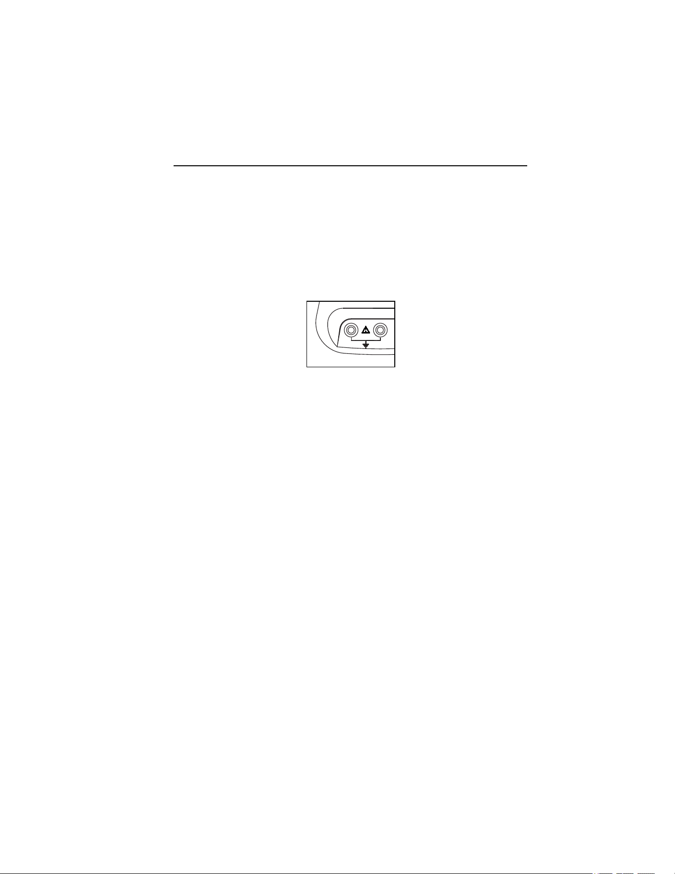
Voltage Measuring Input
The maximum input voltage for over-voltage category CAT IV may not
exceed 600 V to earth ground (825 V line to line voltage).
Figure 1 shows the voltage measuring input of the Clamp Meter.
COM V
600V
eln02.eps
Figure 1. Voltage Measuring Input
Note
• Do not remove any covers other than the cover of the battery
compartment.
• Refer all servicing to qualified personnel.
• The device may only be used indoors.
Power Adapter and USB Connection
Line power voltage may be set with the slider switch on BE345 Battery
Charger/Power Adapter to shown in Figure 2; settings are for 115 V or 230 V
installations.
eln01.bmp
Figure 2. Slider Switch for Line Power Voltage (115 V and 230 V)
1.888.610.7664 sales@GlobalTestSupply.com
Fluke-Direct.com

345
Users Manual
16
W X Warning
• Use only the power supply, Battery Charger/Power
Adapter (Model BE345).
• Before use check that the selected voltage range
indicated on the BE345 matches the local line
power voltage and frequency (refer to Figure 2). If
necessary, set the slider switch of the BE345 to the
correct voltage.
• For the BE345, use only ac line plug adapters or ac
line cords that comply with local safety regulations.
The power (mains) source must conform to the following input ranges/values:
• Euro/UK adapter: 210...264 VAC, 47...53 Hz/ 8 VA
• US Adapter: 100…120 VAC, 57…63 Hz/ 8VA
Figure 3 shows the power adapter and USB ports for the Clamp Meter.
USB
eln03.eps
Figure 3. Power Adapter and USB Connection
Voltage measuring inputs should be disconnected before attaching the USB
cable to a PC. Saved data may be downloaded to a PC using the supplied USB
cable; review saved data using the software included on the CD.
Design and Functions
This section provides an overview of the terminals, ports, and interfaces of the
Clamp Meter, as well as a list of display and operating devices, and a brief
introduction to the basic functions.
1.888.610.7664 sales@GlobalTestSupply.com
Fluke-Direct.com
Power Quality Clamp Meter
Design and Functions
17
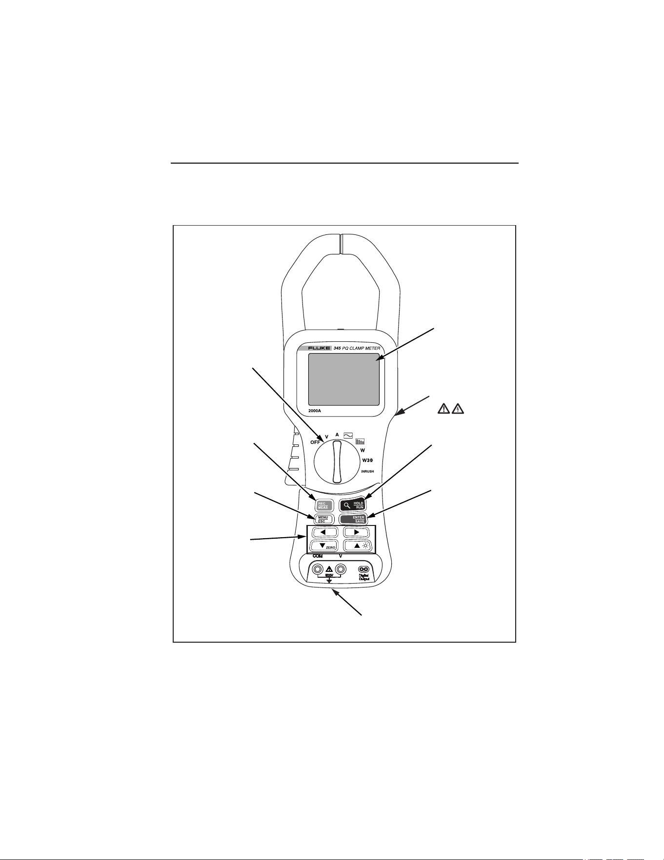
Front View
Figure 4 shows the front view of the 345 Power Quality Clamp Meter.
+
Colour display
transmissive LCD
320 x 240 pixels
(70mm diagonal)
Run / Hold
stops or starts
measurement
function
Save / Enter Store
measurement
screen or select
menu item
Voltage input terminals
up to 600V (RMS)
Cursor keys
directs cursor
around menus
and moves
measurement
cursors.
Menu / Esc
access menu
or go up one
menu level.
Record / Measure
key selects
measurement
or recording
function
Function Selector
Turn for required
measurement
function
Tactile Barrier
eln04.eps
Figure 4. 345 Front View
1.888.610.7664 sales@GlobalTestSupply.com
Fluke-Direct.com
345
Users Manual
18
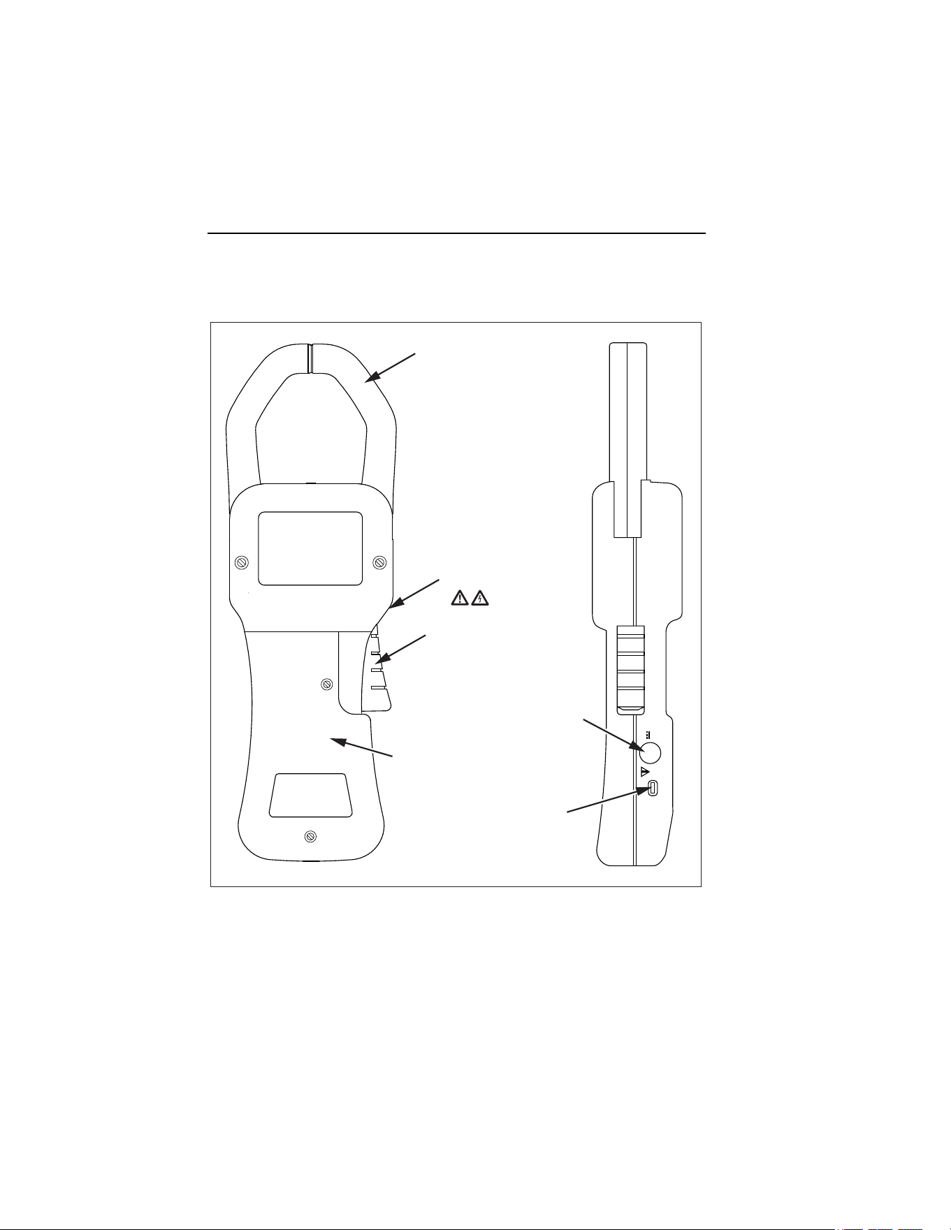
Rear and Side View
Figure 5 shows the rear and side view of the 345 Power Quality Clamp Meter.
Current Clamp
Current
Clamp
trigger
DC Power Input
Current Cover
USB Port
Tactile Barrier
eln05.eps
Figure 5. Rear and Side View
1.888.610.7664 sales@GlobalTestSupply.com
Fluke-Direct.com

Power Quality Clamp Meter
Using the Clamp Meter
19
Using the Clamp Meter
Check the Shipment
Before using the Clamp Meter for the first time, ensure the shipment is
complete using the following list and the delivery specifications:
• 1 345 Power Quality Clamp Meter
• 1 Users Manual
• 1 Battery Charger/Power Adaptor (BE345)
• 1 set of voltage measuring leads
• 1 CD-ROM containing software
• 1 USB cable for connection to PC
• 1 carrying case
Preparing Clamp Meter for Use
Follow the safety instructions regarding ambient conditions and location of
installation.
Initial Setup
W X Warning
With the devices connected to the power mains, a number
of internal components are live with dangerous voltage
levels. Utilization of leads and accessories that do not
meet relevant safety standards could lead to serious injury
or death from electric shock.
The Clamp Meter is delivered with six AA cells installed in the instrument,
and is ready for use.
A mains power adapter BE345 is also supplied. This universal power adaptor
is delivered with a plug suitable for your country. The correct plug should be
selected at the time of ordering or purchase from those available.
This BE345 adapter should be used to maintain power when logging
measurements to the Clamp Meter’s internal memory.
1.888.610.7664 sales@GlobalTestSupply.com
Fluke-Direct.com

345
Users Manual
20
Note
The Clamp Meter operates from standard alkaline cells. The batteries
are bypassed when the mains adaptor is plugged in to the Clamp
Meter and a power source.
Rechargeable cells cannot be charged inside the instrument.
Switching the Clamp Meter On
To turn on the Clamp Meter:
1. Turn the central rotary selector to selected measurement position.
2. The device is now ready for operation.
Figure 6 displays the battery life screen following start-up.
eln06.bmp
Figure 6. Battery Life Screen of Clamp Meter
3. The instrument will auto zero the current measuring circuit during the
start-up period, and the progress of the process is indicated on the
display.
1.888.610.7664 sales@GlobalTestSupply.com
Fluke-Direct.com

Power Quality Clamp Meter
Connection to Circuits
21
Switching the Device Off
To switch the device off:
1. Turn the rotary switch to the OFF position.
2. If the device is not to be used for a prolonged period of time,
disconnect the power adaptor, and store the Clamp Meter and
accessories in the supplied carrying case.
Connection to Circuits
W X Warning
Prior to connecting the circuits, ensure that the maximum
measuring voltage and maximum voltage to earth ground
(1000 V CATIII and 600 V CATIV, respectively) will not be
exceeded.
Wear suitable Personal Protective Equipment (PPE) when
carrying out measurements with the Clamp Meter.
Connecting Sequence
For safety reasons, when connecting a circuit to the Clamp Meter, proceed in
the following sequence:
1. Turn on the Clamp Meter (utilize the ac power adapter if recording is
required).
2. Connect the measuring circuit as shown in the relevant connection
diagrams that follow.
3. To ensure the measured values are indicated correctly, confirm that
the phase is connected to HI so that the energy flow is from HI to LO.
4. Observe the correct direction of current during measurements; the
correct direction is indicated by an arrow on top of the Clamp Meter.
1.888.610.7664 sales@GlobalTestSupply.com
Fluke-Direct.com

345
Users Manual
22
Overview
The Clamp Meter offers the following options for connection:
• Single-phase connection for voltage measurement.
• Single-phase connection for current measurement.
• Single-phase connection for power measurement.
• Three-phase connection for balanced power.
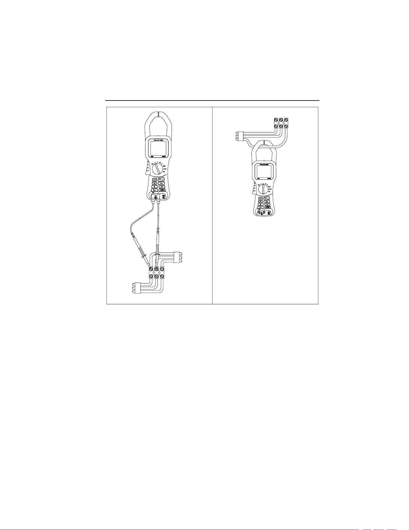
Voltage and Current Measurements
W X Warning
You could be seriously injured when touching
connections, internal circuits, and measuring devices that
are not properly connected to earth ground.
Note
Always adhere to the instructions regarding the sequence of
connection.
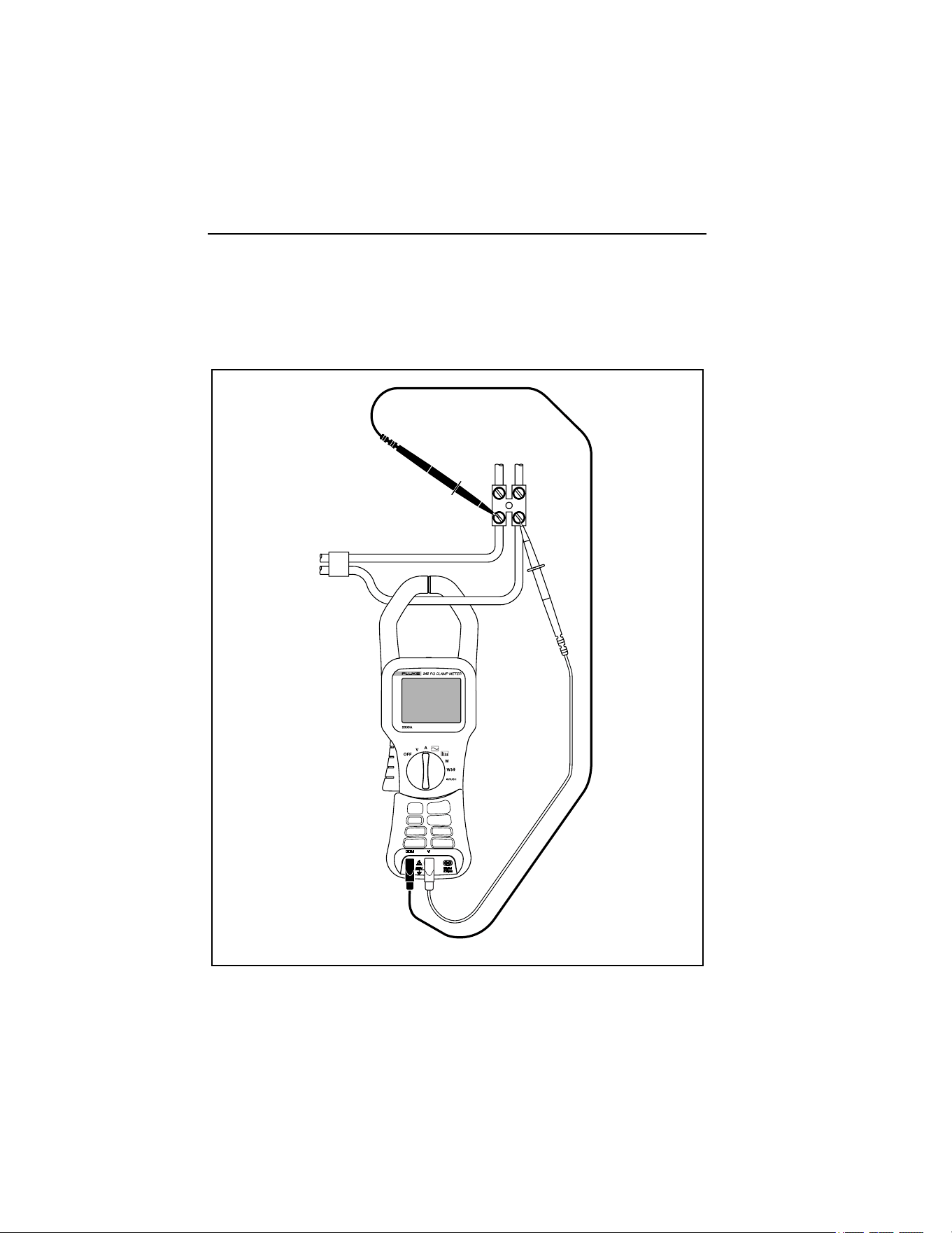
Figure 7 shows the connections for voltage and current measurements. The
image on the left depicts voltage measurement, while the image on the right
illustrates current measurement.
1.888.610.7664 sales@GlobalTestSupply.com
Fluke-Direct.com
Power Quality Clamp Meter
Connection to Circuits
23
eln07.eps
Figure 7. Voltage and Current Measurement Connections
1.888.610.7664 sales@GlobalTestSupply.com
Fluke-Direct.com
345
Users Manual
24
Single Phase Power Measurement Connection
The Clamp Meter is well designed for measurement of single-phase power
networks.
Figure 8 shows the required connections for single-phase power measurement.
eln08.eps
Figure 8. Single-Phase Power Measurement Connection
1.888.610.7664 sales@GlobalTestSupply.com
Fluke-Direct.com

Power Quality Clamp Meter
Connection to Circuits
25
Note
Carefully observe the direction of the current flow on the top of the
Clamp Meter.
Note
Always adhere to the instructions regarding the sequence of
connection.
Balanced Three-Phase Power Measurement Connection
In three-phase power networks where the load may be considered to be
balanced, the Clamp Meter may be used to make some basic measurements
such as watts, VA, PF, and kWHr.
Note
This measurement is only suitable for balanced loads. It is not
suitable for measurements other than nominally balanced, due to the
consideration of only one current phase.
Current is measured on one phase and the two voltages are measured on the
remaining phase.
Figure 9 shows the three-phase setup screen for the balanced three-phase
power measurement.
1.888.610.7664 sales@GlobalTestSupply.com
Fluke-Direct.com

345
Users Manual
26
eln09.bmp
Figure 9. Three-Phase Power Connection
Note
Always adhere to the instructions regarding the sequence of
connection.
Configuration
Operating Controls and Display
This section familiarizes you with some basic control elements, such as the
display and the connections for the Clamp Meter.
The Clamp Meter is turned on and off by rotating the central selector switch.
Turn the selector clockwise for ON and counterclockwise to turn OFF. Each
of the available measuring functions is selected by turning the rotary selector
to the required position.
1.888.610.7664 sales@GlobalTestSupply.com
Fluke-Direct.com
Power Quality Clamp Meter
Configuration
27
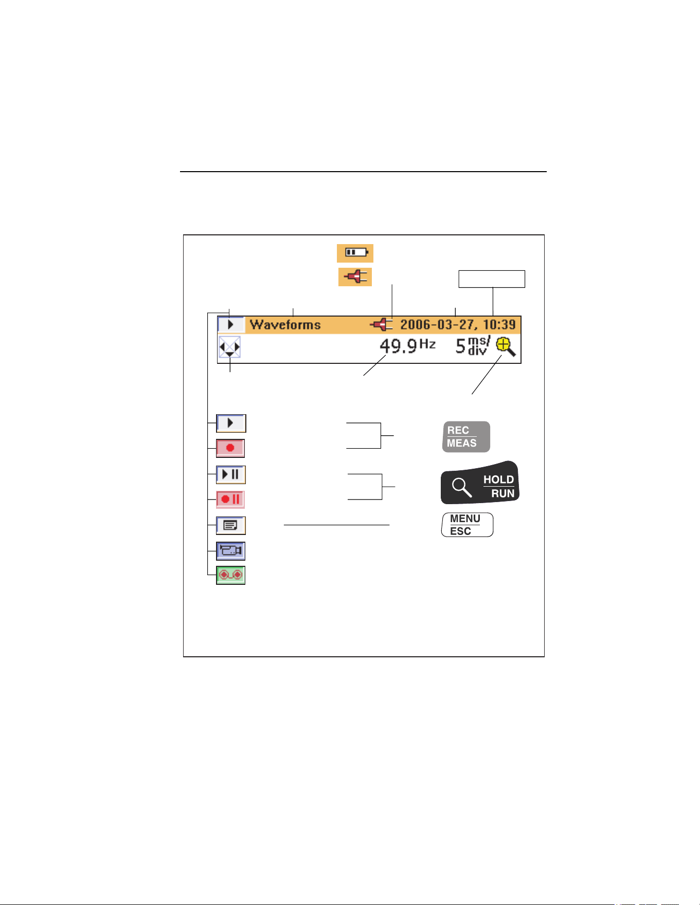
Display Symbols
Figure 10 details the display symbols of the Clamp Meter.
+
Power supply:
Battery operation
Mains operation
Headline bar
Date and Time
Measured frequency
Measuring mode
Logging mode
Active
with:
Active
with:
Active
with:
Hold in measuring mode
Hold in logging mode
Menu
Display of stored data
Display of logged data
The headline bar changes colour depending on mode:
Orange : measuring mode
Red : recording mode
Zoom function (where available)
Current measuring function
Status display
NAVkey - Indicates
direction of
available screens
eln10.eps
Figure 10. Display Symbols of Clamp Meter
Available battery power is indicated as a set of bars. Four bars indicate
maximum, one bar warns of minimum power, and no bars indicates batteries
may fail within the next 30 minutes. All levels are approximate.
1.888.610.7664 sales@GlobalTestSupply.com
Fluke-Direct.com
345
Users Manual
28
Navigation and Measuring Keys
All basic adjustments of the Clamp Meter are made through the main menu.
Table 2 shows the keys and their respective functions.
Table 2. Navigation and Measuring Keys
Keys Function
M
Used to call up the main menu
JK
Navigate up and down through menu options
[
Indicates the direction to move through menu
FG
Used to select available items
R S
Indicates the available items
Indicates the further items available in a sub-menu
E
Used to access items available in a sub-menu and to save
settings indicated onscreen. Also used to exit the setup
menu, noted on the menu display as Select
Navigation through the Display
Use the navigation keys to navigate through the display and the menus.
Figure 11 shows the choices available when navigating through the display.
1.888.610.7664 sales@GlobalTestSupply.com
Fluke-Direct.com
Power Quality Clamp Meter
Measurement Setup
29
eln11.bmp
Figure 11. Navigation through the Display
Measurement Setup
Basic Adjustments Required before Measuring
Before making measurements, some basic items must be considered, such as:
Auto Power Down: Select OFF (or ON to conserve battery life).
Voltage ranging: Voltage range may be selected for automatic or
manual operation (4 V, 40 V, 400 V and 750 V).
Current ranging: Current range may be selected to operate
automatically or manually (40 A, 400 A and 2000 A).
1.888.610.7664 sales@GlobalTestSupply.com
Fluke-Direct.com

345
Users Manual
30
Additional instrument settings include:
Low pass filter: Switch low pass filter ON or OFF to eliminate high
frequency noise.
PF/DPF Mode: Select either Power Factor or Displacement Power Factor.
PF/DPF Display: Select displayed Power Factor.
Harmonics type: Select either %H1 (fundamental) or %RMS.
Date and Time: For time and date stamping of logged data.
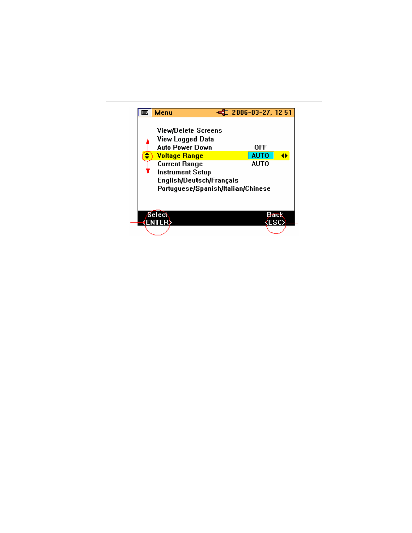
Voltage Range Settings
To select either manual or automatic voltage ranging:
1. Press
JK until Voltage Range is selected.
2. Press
FG to change the setting. The available choices are
AUTO, 4 V, 40 V, 400 V, and 750 V.
3. Press
E to confirm required change.
4. To exit without changing, press
M.
Figure 12 shows the voltage range settings for the Clamp Meter.
eln14.bmp
Figure 12. Voltage Range Settings
1.888.610.7664 sales@GlobalTestSupply.com
Fluke-Direct.com

Power Quality Clamp Meter
Measurement Setup
31
Current Range Settings
To select either manual or automatic current ranging:
1. Press
JK until Current Range is selected.
2. Press
FG to change the setting. The available choices are
AUTO, 40 A, 400 A, and 2000 A.
3. Press
E to confirm selection.
4. To exit without changing, press
M.
Figure 13 shows the current range settings for the Clamp Meter.
eln15.bmp
Figure 13. Current Range Settings
Additional Instrument Settings
To view or adjust the additional settings:
1. Select Instrument Setup from the main menu.
2. Press
E to go activate the settings sub-menu.
3. Press
JK to move cursor to the required item.
1.888.610.7664 sales@GlobalTestSupply.com
Fluke-Direct.com

345
Users Manual
32
Figure 14 shows the available additional instrument settings for the Clamp
Meter.
eln16.bmp
Figure 14. Additional Instrument Settings Menu
The items available in the additional Instrument Settings are:
• Low Pass Filter
• PF/DPF Mode
• PF/DPF Display
• Harmonics Type
• Buzzer Volume
These items may be changed by using the
FG keys.
Press
E to confirm selections, or press M to exit without changing.
The Date and Time, Display Contrast, and Version and Calibration have sub-
menus that are accessed by pressing
E and the changes are effected in
the same manner as previously detailed selections.
1.888.610.7664 sales@GlobalTestSupply.com
Fluke-Direct.com

Power Quality Clamp Meter
Measurements
33
Figure 15 shows the items available in the additional instrument settings.
eln17.bmp
Figure 15. Additional Instrument Setting Items
Measurements
Measurement Tips
Displaying Measurements
When the Clamp Meter is in measurement mode, generally more than one set
of the measurements will be available.
Note
For more details, refer to each measuring mode in the “Measuring
Functions Overview” section.
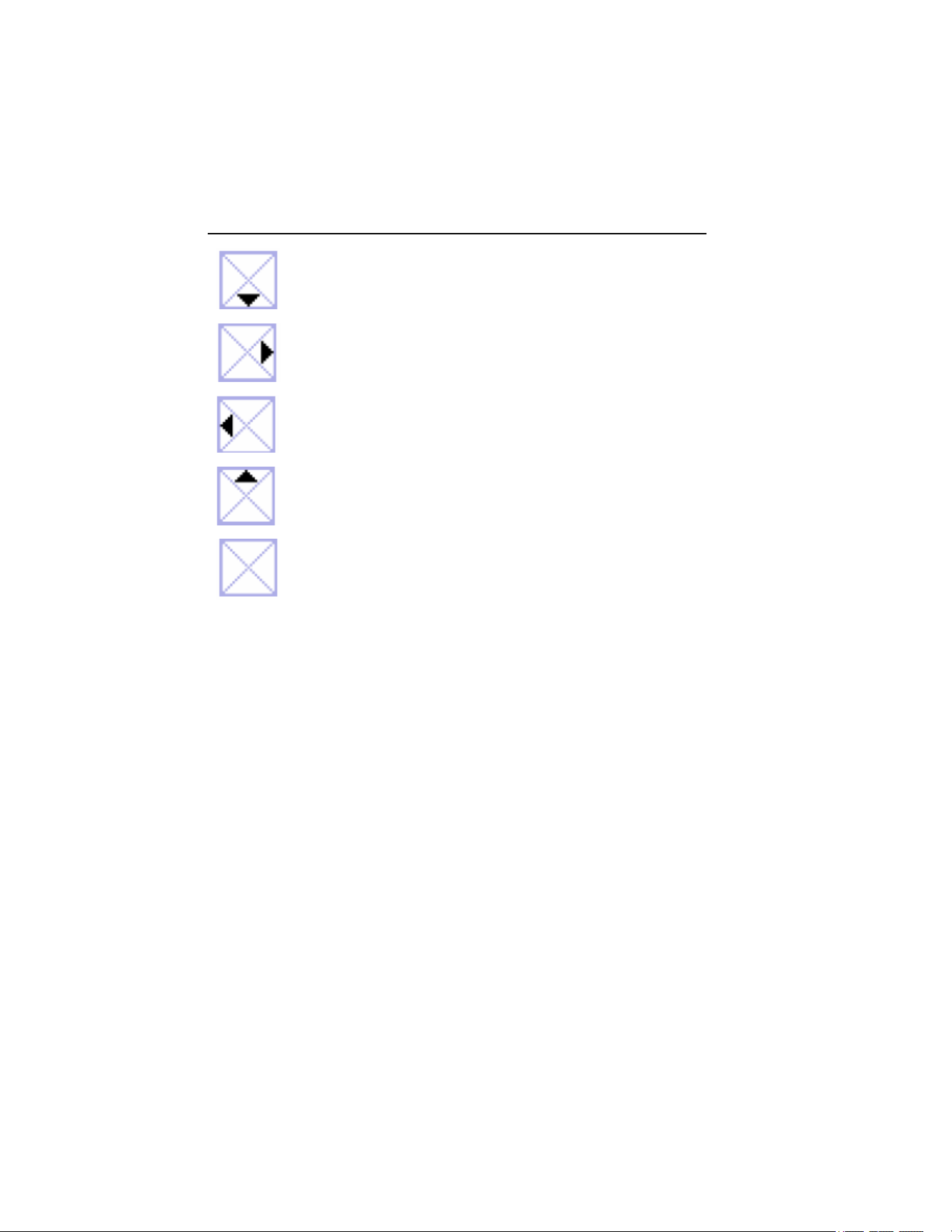
The availability of additional screens is indicated by the navigation keys
symbol
that appears in the top left hand side of the display screen. The
functions can be summarized as:
1.888.610.7664 sales@GlobalTestSupply.com
Fluke-Direct.com
345
Users Manual
34
Is activated with
J
Is activated with
G
Is activated with
F
Is activated with
K
Indicates there are no other
active screens
The required measurement parameters can be displayed by pressing their
associated keys.
Saving Measurement Screens
During the measurement process, the display may be capture for viewing or
later download.
To save a measurement screen:
1. Press
E to initiate screen saving. The following message is
displayed.
1.888.610.7664 sales@GlobalTestSupply.com
Fluke-Direct.com

Power Quality Clamp Meter
Measurements
35
eln18.bmp
2. Press E to accept the screen displayed.
The screens are saved sequentially in the available memory locations. There
are a total of 50 locations available.
The saved screen may be managed, that is, viewed and deleted, using the main
menu. When the screen is saved, the following information is used to label the
screen in memory:
• Measurement type
• Measurement state (Run or Hold)
• Date and time stamp
Viewing Saved Screens
To view the saved screens:
1. Press
M to access the main menu. View/Delete Screens is the first
available option in the menu.
2. Press
E to go to View. The following screen is displayed.
1.888.610.7664 sales@GlobalTestSupply.com
Fluke-Direct.com

345
Users Manual
36
eln19.bmp
3. Press JK to select the screen required for viewing; recall
the screen by pressing
E when the saved screen is highlighted.
4. Press
E and the saved screen is displayed.
W Note
A warning is displayed at the top of the screen to indicate that the
readings are not the active measurements. Screens may also be
deleted in this mode.
Logging Tips
The Clamp Meter allows three kinds of Logging, and logged data is made up
of average values. The detailed steps are outlined below, following a series of
preliminary setup adjustments to ensure continuous power while recording or
Logging.
1.888.610.7664 sales@GlobalTestSupply.com
Fluke-Direct.com

Power Quality Clamp Meter
Measurements
37
Note
The Auto ranging option is initially highlighted, although it is
recommended that the Auto ranging be switched off. Otherwise, if the
instrument re-ranges during the recording scaling, there may be a
gap in the recording as the instrument stabilizes.
Step 1 – Instrument Setup:
To setup the instrument:
1. Select an item using JK andFG.
2. Press
H to go to the next step as shown in the following display.
eln21.bmp
3. The battery save function may also be activated or deactivated in this
screen.
4. Press
H to go to the next step.
Note
It is recommended that the power adaptor be connected during
Logging. If power to the adaptor is interrupted during the recording,
the Clamp Meter internal batteries will continue to power the
instrument.
1.888.610.7664 sales@GlobalTestSupply.com
Fluke-Direct.com

345
Users Manual
38
The Battery Save function is still available when recording without
the power adaptor connected.
This function is switched on or off using the FG keys. In
this mode the instrument switches itself off after approximately
5 minutes to preserve battery power. The initiation of the power down
function is indicated by an intermittent audible bleep.
Step 2 – Logging Setup:
Logging (recording) is initiated by pressing and holding
R for
approximately 3 seconds or until the Logging Area screen is displayed. On
pressing the
R button again, the step-by -step recording process begins.
The Clamp Meter has three logging areas available; recording area 1 is
selected by default, as shown in the following display.
eln22.bmp
Select the Logging Area using F and G. There are actually four
options to choose from: logging area 1, 2, and 3, or logging areas 1-2-3
combined for a longer logging time.
Any data present in Logging Area will be over-written during the logging
process.
1.888.610.7664 sales@GlobalTestSupply.com
Fluke-Direct.com

Power Quality Clamp Meter
Measurements
39
Logged data is made up of averaged values. There are standard averaging
times of 1, 2, 5, 10, 30 seconds and 1, 5, 10 and 15 minutes. Additionally, it is
possible to customize the averaging time from 1 second to 900 seconds in 1-
second steps.
The averaging time is selected by highlighting the item Averaging Time and
using the FG keys to select the required time, as shown in the
following display.
eln23.bmp
If a non-standard averaging time is required, the Custom Setting may be
highlighted using the JK keys.
Use FG and JK to select the requested averaging time.
The available logging time is indicated based on the logging area chosen and
the average time selected. The logging time will vary depending on the
measurement position. The logging times for each measurement mode and the
available averages are detailed in the “Logging Times for Each Measurement
Mode and Averages” section.
Press
H to start recording. The message LOGGING is displayed, and then
a trace appears on the instrument display as shown in the following display.
1.888.610.7664 sales@GlobalTestSupply.com
Fluke-Direct.com

345
Users Manual
40
eln24.bmp
During the logging, the available measurements (and logged values) may be
accessed using the navigation keys (see “Navigation and Measuring Keys”
section). During the logging, the average values (the minimum and maximum
values) are recorded for each average period, as shown in the following
display.
eln25.bmp
1.888.610.7664 sales@GlobalTestSupply.com
Fluke-Direct.com

Power Quality Clamp Meter
Measurements
41
The minimum and maximum values are based on half-cycle RMS values.
Minimum and maximum values are indicated by blue and red triangles on the
respective graphed values.
During logging, the headline bar is highlighted in red.
Logging may be stopped by pressing
R and a message Stop Logging? is
displayed; to halt logging, press
E key as shown in the following
display.
eln26.bmp
If the rotary switch position is changed during the logging, the message Stop
Logging? appears onscreen; confirm by pressing
Eto end logging.
Alternatively, return the rotary switch to the original measurement position,
and recording will continue.
Any logged data present in the Clamp Meter can be checked by pressing
M
and selecting the “View Logged Data” menu item.
Press JK and select record with
E as shown in the following
display.
1.888.610.7664 sales@GlobalTestSupply.com
Fluke-Direct.com

345
Users Manual
42
eln27.bmp
The log number and type of recording is shown with date and time stamp.
The logged data may be downloaded from the Clamp Meter via the USB cable
and analyzed in detail on a PC using the supplied Power Log software package
included on the CD.
Measurement Function Overview
Measurement modes are selected using the central rotary switch.
Voltage Measurements
The measurements available in measurement mode are described in Table 3.
1.888.610.7664 sales@GlobalTestSupply.com
Fluke-Direct.com
Power Quality Clamp Meter
Measurement Function Overview
43
Table 3. Voltage Measurements
Measurement Notation Scales and
Ranging
Associated Items and
Comments
RMS voltage V rms
dc voltage V dc
ac voltage V ac
Average voltage V avg
Peak voltage V pk
Volts frequency
ratio
V/Hz
Voltage ripple %RPL
Voltage crest
factor
CF
Frequency Hz
Auto ranging
or Manual
Minimum and maximum of
all values. Recording of
average values available.
Total run time indicated in
recording mode
The following nominal value display screen is shown by default on entering
the volts measurement mode.
eln28.bmp
1.888.610.7664 sales@GlobalTestSupply.com
Fluke-Direct.com

345
Users Manual
44
Two major values are displayed initially. Additional values may be accessed
by pressing
J, which displays the following six-value screen.
eln29.bmp
Return to the previous screen by pressing K.
The Minimum/Maximum value screens may be accessed by pressing
R. The
live value will be displayed initially. In addition, the time (or Run Time)
elapsed since the time the button was pressed will be indicated above the
measurement in green text.
The minimum value (REC – MIN) registered during the elapsed period may be
accessed by pressing
G. Additional presses will show the maximum
registered value (REC – MAX) and average value (REC – AVG).
Pressing
F reverses the viewing process.
Note
Over-range values are indicated for all measurements with:
.
This applies to all measured values. Ensure the correct range is
selected before proceeding to make any measurements.
1.888.610.7664 sales@GlobalTestSupply.com
Fluke-Direct.com
Power Quality Clamp Meter
Measurement Function Overview
45
Current Measurement
The measurements available in Current Measurement mode are described in
Table 4.
Table 4. Current Measurements
Measurement Notation Scales and
Ranging
Associated Items and
Comments
RMS current A rms
dc current A dc
ac current A ac
Average current A avg
Peak current A pk
Current/frequency
ratio
A/Hz
Current ripple %RPL
Current crest factor CF
Auto ranging or
Manual
Frequency also
indicated.
Minimum and maximum
of all values. Recording
of average values
available.
Total run time indicated
in recording mode
Navigation around the measurement screens and recording current are carried
out in the same way as in the voltage mode.
DWaveforms
The measurements available in Waveforms mode are described in Table 5.
Table 5. Waveforms Measurements
Measurement Notation Scales and
Ranging
Associated Items
and Comments
Voltage and Current
waveforms
V+I
waveforms
Two scales
Voltage waveform V waveform One scale
Current waveform A waveform One scale
Voltage and Current
waveforms
V+I
waveforms
One scale
Waveform phase
difference and
frequency.
Sample value selected
by measurement
cursor
1.888.610.7664 sales@GlobalTestSupply.com
Fluke-Direct.com

345
Users Manual
46
This measuring function shows the voltages and currents in oscilloscope form,
as well as their instantaneous values at the cursor position. This function
clearly represents current and voltage waveforms and any distortion present.
On entry to Waveforms mode, the time base is set to 5 ms/div. The symbol B
is shown next to this setting to indicate that a 2 sec press of the HOLD/RUN
button will change the setting. So long as a plus sign is shown, the sweep
speed can be increased. The minus sign is shown at 2.5 ms/div, when at the
maximum speed.
The dual scale display screen shows the measured waveforms on separate grids
with appropriate scales as in the display below.
eln30.bmp
The frequency and phase difference are displayed above the waveforms.
The available time base values are 50, 25, 10, 5, and 2.5 ms/division.
Note
If a short press of
H
is made, the instrument enters the HOLD
mode, and
H
must be pressed again to return to RUN mode before
the time base can be changed.
1.888.610.7664 sales@GlobalTestSupply.com
Fluke-Direct.com

Power Quality Clamp Meter
Measurement Function Overview
47
The single scale display shows the waveforms at maximum magnification with
the V and A scales at either side of the waveforms, as shown in the following
display.
eln31.bmp
The measurement cursor may be positioned using the keys FG and
the time (T=n ms) is indicated on moving the marker.
LHarmonics
Harmonics are sinusoidal voltage and current with a frequency that
corresponds to an integer multiple of the fundamental of the mains (line)
voltage. Any signal can be split into an infinite number of sine waves of
different frequency and amplitude. The contribution of each of these individual
sine waves is represented in a bar chart up to the 40
th
harmonic. The smaller
the harmonics (starting from the 2
nd
harmonic, as the 1
st
is the fundamental),
the better the power quality. Harmonics are an indication of the distortion
present in the measured parameter. This is displayed as % total harmonic
distortion (%THD) or distortion factor (%DF).
Harmonics may be represented as a percentage of the fundamental value
(%H1) or as a percentage of the measured RMS value (%RMS) (See Table 6).
1.888.610.7664 sales@GlobalTestSupply.com
Fluke-Direct.com

345
Users Manual
48
Table 6. Harmonics Measurements
Measurement Notation Scales and
Ranging
Associated Items
and Comments
Voltage
harmonics
V
fund to V40th
1st to the 40th
Current
harmonics
V
fund to V40th
1st to the 40th
Adjustable zoom
scale (100 %,
40 %, 10 % and
4 %)
RMS parameter,
THD, individual
harmonic value (V, A
or W) or as % of
fundamental or % of
distortion factor
On first selecting the harmonics mode the ac RMS voltage and % distortion
factor are displayed as shown following display.
eln32.bmp
Other associated measured values are available by pressing the J key.
1.888.610.7664 sales@GlobalTestSupply.com
Fluke-Direct.com

Power Quality Clamp Meter
Measurement Function Overview
49
The second screen shows the fundamental voltage ac (V ac [1]) and %THD as
shown in the following display.
eln33.bmp
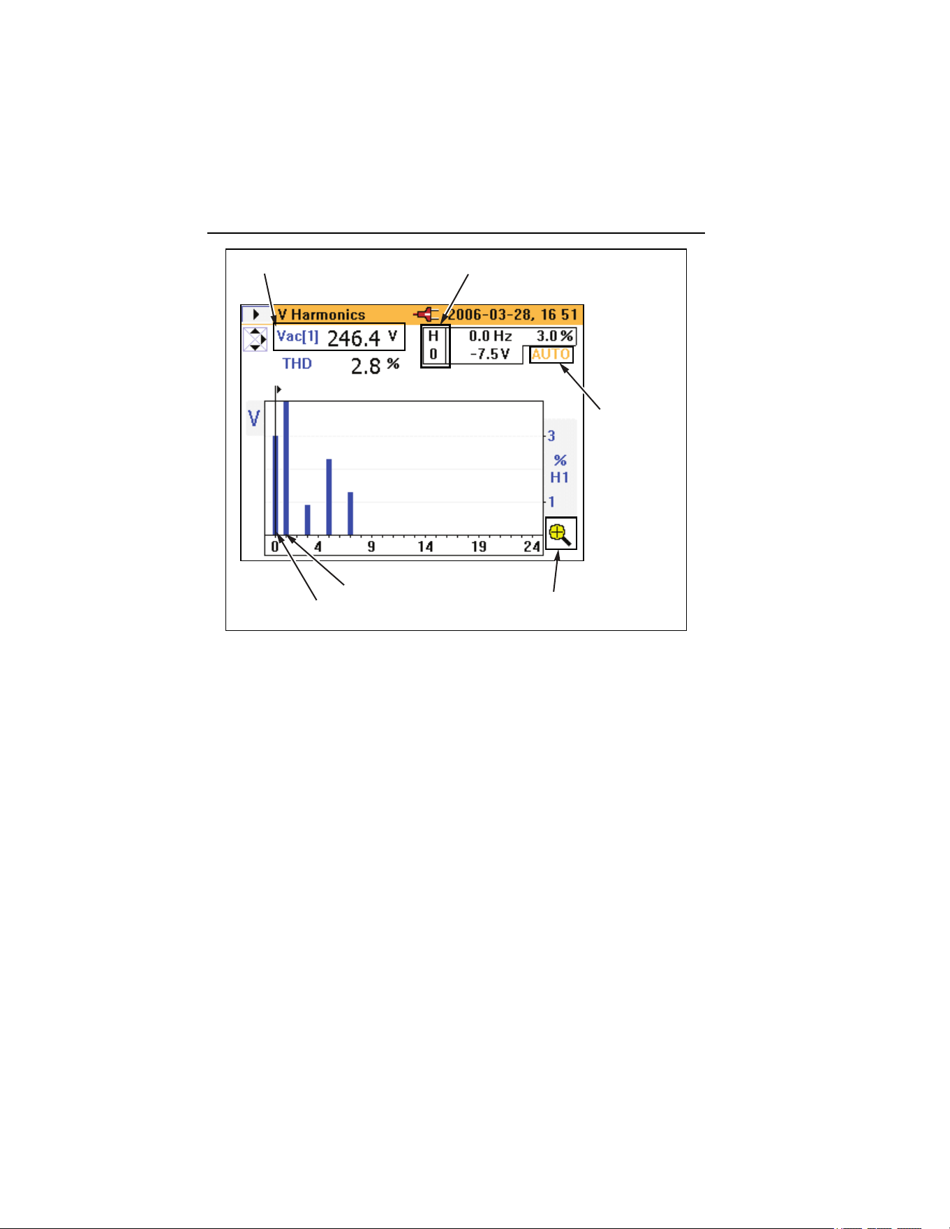
As shown below in the A Harmonics screen, AUTO indicates the percentage is
automatically scaled to the max of H (2) and above. Pressing the H key for
3 seconds allows the scaling between values of 100 %, 40 %, 10 %, or 4 %,
and then back to AUTO. The automatic scaling feature is necessary, as
theoretically any harmonic beyond the fundamental can be as high as 600 %
with respect to the fundamental (H (1)), since the Clamp Meter supports THD
to 660 %. While 100 % can never be exceeded if %RMS is chosen from the
menu, the scale could go as high 700 % if harmonic type %H1 had been
selected. A scaling above 100 % is only available in the AUTO mode, where
the scaling could be 200, 300, 400, 500, 600, or 700 % full scale.
1.888.610.7664 sales@GlobalTestSupply.com
Fluke-Direct.com
345
Users Manual
50
Measured value selected by cursor
Fundamental value
indicates
% scale has
been selected
automatically
indicates whether % scale
magnification is available
H(1) / Fundamental
H(0) DC component
eln34.eps
A- detailed picture for current harmonics is presented in the same way.
The point at which input is over- or under-range is displayed as measured
values in the following V Harmonics screen example.
1.888.610.7664 sales@GlobalTestSupply.com
Fluke-Direct.com

Power Quality Clamp Meter
Measurement Function Overview
51
eln35.bmp
The scale is automatically set to 100 % and the overload (OL) symbol is
displayed.
Harmonic Recording
Harmonic recording mode has two separate modes:
Mode Recorded
Harmonics
V (Voltage) Vfund to V40th
A (Current) Ifund to I40th
On entering the logging mode while still measuring harmonics, the mode
voltage (V) or current (A) must be selected, as shown in the following Log-
Harmonics screen.
1.888.610.7664 sales@GlobalTestSupply.com
Fluke-Direct.com

345
Users Manual
52
eln36.bmp
The length of the time taken for recording will depend on the mode and
recording area chosen. The type of harmonics to be logged, %H1 or %RMS,
can also be selected.
Unlike other recording modes, the recorded parameter is not shown as a line
recording against time on the instrument display. In this mode, the minimum
and maximum values are shown as an orange bar; superimposed on the orange
bar is a flat black bar that represents the most recently available measured
value, as shown in the following display.
1.888.610.7664 sales@GlobalTestSupply.com
Fluke-Direct.com

Power Quality Clamp Meter
Measurement Function Overview
53
eln37.bmp
The upper part of the orange bar is the maximum value of the harmonic, and
the lowest part of the orange bar is the minimum value measured during the
logging period. The elapsed time of the logging period is displayed as Run
Time on the display.
The cursor may be moved left or right to select individual harmonics from dc
to the 40
th
harmonic.
Figure 16 shows the detailed view of the harmonic recording display.
eln38.bmp
Figure 16. Detailed View of Harmonic Recording Display
1.888.610.7664 sales@GlobalTestSupply.com
Fluke-Direct.com
345
Users Manual
54
WPower
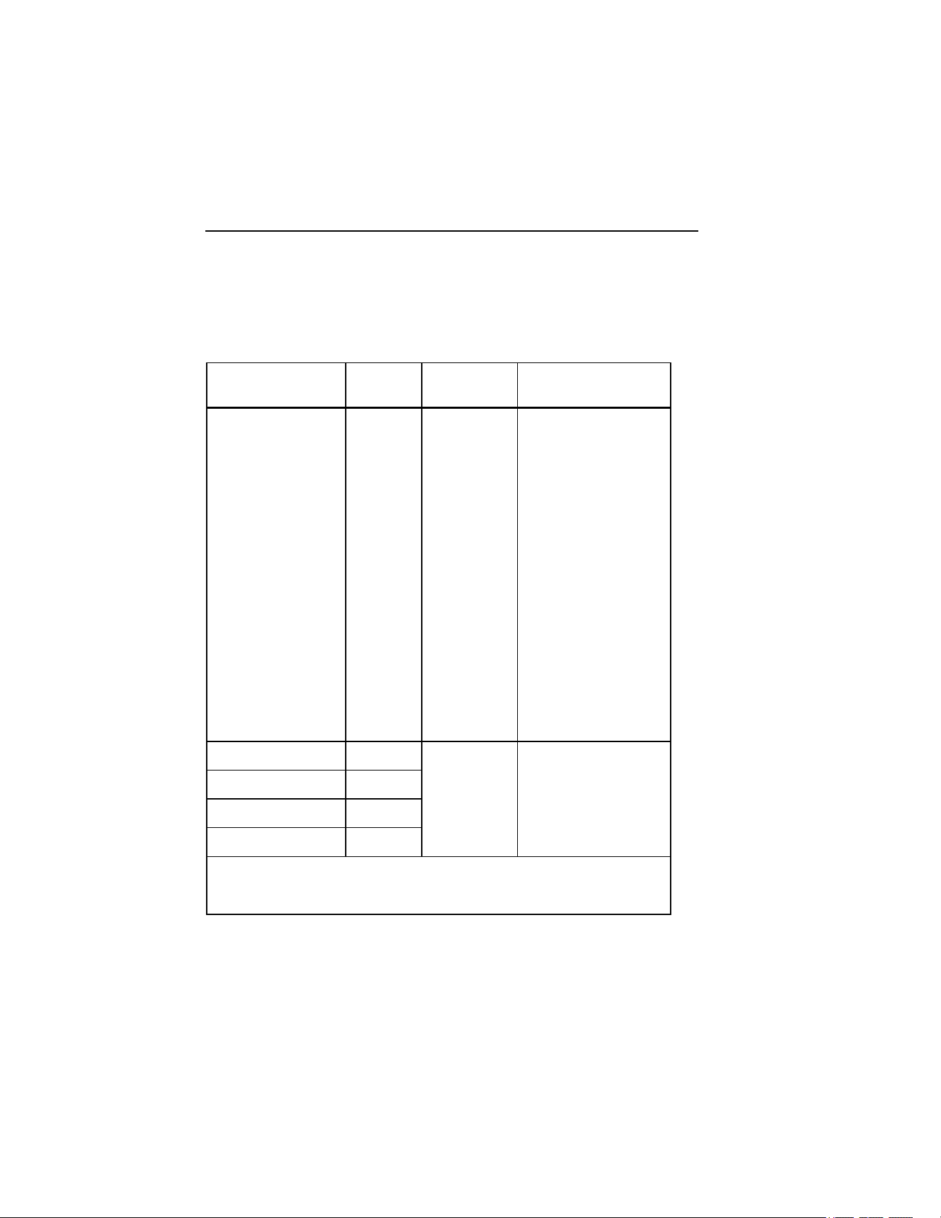
The measured power and associated variables for this function are described in
Table 7.
Table 7. Power
Measurement Notation Scales and
Ranging
Associated Items and
Comments
Power kW
Apparent Power kVA
Reactive Power kVAR
Power Factor* PF
Power Factor in
degrees (cos φ)*
PF°
Displacement Power
Factor*
DPF
Displacement Power
Factor in degrees
(cos φ)*
DPF°
Voltage Vac(1)
Current Iac(1)
N/A Frequency also
indicated
Minimum and
maximum of all values
Recording of average
values available
Energy** kWHr
Apparent energy** kVAHr
Reactive energy** kVARHr
Ampere hours** AHr
Measurement of these
items is started in REC
and logging mode.
Total run time indicated
on the display.
* Selectable through instrument setup menu
** Available in power logging mode
1.888.610.7664 sales@GlobalTestSupply.com
Fluke-Direct.com

Power Quality Clamp Meter
Measurement Function Overview
55
The measurement displays in the power mode offer all the available
measurements on one screen as shown in the following display.
eln39.bmp
Initiating power logging is the same process used in the V and A modes.
Energy measurements are available while logging or REC mode. Since W is a
signed value, WHr can go up or down, and can be either side of the zero axis.
The same is true of VARHr as shown in the following display.
1.888.610.7664 sales@GlobalTestSupply.com
Fluke-Direct.com

345
Users Manual
56
eln40.bmp
VA and AHr is unsigned, so can never decrease and never be below the zero
axis as shown in the following display.
eln41.bmp
1.888.610.7664 sales@GlobalTestSupply.com
Fluke-Direct.com
Power Quality Clamp Meter
Measurement Function Overview
57
XThree-Phase Power
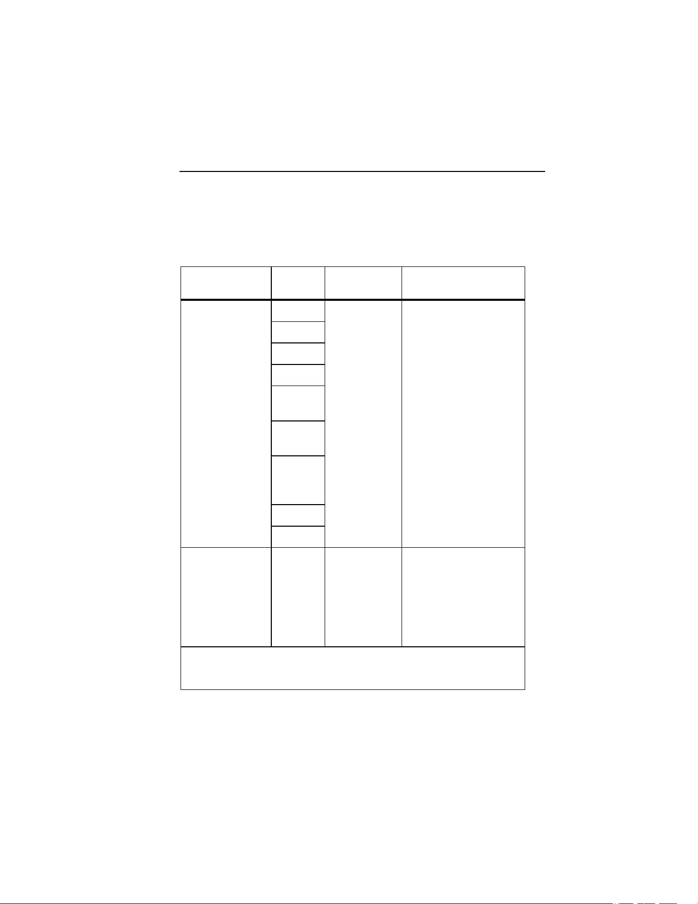
The three-phase power measurement and associated variables for this function
are described in Table 8.
Table 8. Three Phase Power
Measurement Notation Scales and
Ranging
Associated Items and
Comments
Power kW
Apparent Power kVA
Reactive Power kVAR
Power Factor* PF
Power Factor in
degrees (cos φ)*
PF°
Displacement
Power Factor*
DPF
Displacement
Power Factor in
degrees (cos φ)*
DPF °
Voltage Vac(1)
Current Iac(1)
N/A Frequency also indicated
Minimum and maximum
of all values
Recording of average
values available
Energy** kWHr
Apparent
energy**
kVAHr
Reactive energy** kVARHr
Ampere hours** AHr
Measurement of these
items is started in REC
and logging mode
Total run time indicated
on the display.
* Selectable through instrument setup menu
** Available in power logging mode
1.888.610.7664 sales@GlobalTestSupply.com
Fluke-Direct.com

345
Users Manual
58
This mode should only be used for balanced three-phase power; only one
current-phase and two separate voltage-phases are considered accurate since
true three-phase power cannot be guaranteed. The connected load must be well
balanced, and connected in either Wye or Delta. This method will not provide
accurate results where there is power distortion present.
For convenience on selecting this mode, a connection diagram is displayed on
the Clamp Meter as shown in the following display.
eln42.bmp
I Current
The Clamp Meter can capture current-triggered events, referred to as inrush
current.
When the rotary selector is turned to the Iposition, the following
screen is displayed.
1.888.610.7664 sales@GlobalTestSupply.com
Fluke-Direct.com

Power Quality Clamp Meter
Measurement Function Overview
59
eln43.bmp
Press R to continue to enter the setup menu and the following screen is
displayed.
eln44.bmp
1.888.610.7664 sales@GlobalTestSupply.com
Fluke-Direct.com

345
Users Manual
60
On this Log-Inrush Current setup screen, the peak current present at the
instrument terminals is displayed (Max peak current) to provide guidance for
the required trigger levels.
The current-trigger level may be selected from either a preset value of 0.5, 1, 3,
10, 30, 100, or 300 A, or a customized value from 0 to 1000 A in 0.1 A steps.
The capture time may also be chosen from 1, 3, 10, 30 100, or 300 seconds.
The capture time refers to the width of the time window on the Clamp Meter
screen.
On pressing
H, the Logging Area settings screen, as shown below, indicates
where the Inrush Current data will be stored. The logging areas 1, 2, 3 or areas
1, 2 and 3 combined may be selected.
eln45.bmp
A single logging area can store about 1000 inrush captures.
Once the required settings are made, the instrument is ready for data capture;
press
H to start the capture.
1.888.610.7664 sales@GlobalTestSupply.com
Fluke-Direct.com

Power Quality Clamp Meter
Measurement Function Overview
61
The Clamp Meter now waits for the trigger (current exceeding the preset level)
as shown in the following display.
eln46.bmp
Once the trigger level is exceeded, the instantaneous values are drawn on the
display and the message Capturing… appears as shown below.
eln47.bmp
1.888.610.7664 sales@GlobalTestSupply.com
Fluke-Direct.com

345
Users Manual
62
Once the inrush event is complete (that is, the capture time has elapsed), the
message WARNING – SCREEN NOT LIVE flashes at the top of the
display.
The Trace value is incremented accordingly as shown in the following display.
In the following example, there are 5 traces stored.
eln48.bmp
Stored traces may be reviewed using the right and left the cursor keys. The
inrush event may now be analyzed by moving the cursor across the captured
signal using the FG keys.
As the cursor is moved, the maximum and minimum vales at that point are
displayed in the top right hand corner of the screen (there will be a group of
values captured for each displayed point on the screen) as shown in the
following display.
1.888.610.7664 sales@GlobalTestSupply.com
Fluke-Direct.com

Power Quality Clamp Meter
Measurement Function Overview
63
eln49.bmp
Once the cursor is in position, the blue marker can be shifted to that position
by pressing the
H key.
The cursor may now be moved again and the relative time (T=) will be
indicated below the graph, as shown in the following display.
eln50.bmp
1.888.610.7664 sales@GlobalTestSupply.com
Fluke-Direct.com

345
Users Manual
64
If additional inrush events are to be captured after exiting the inrush mode,
these may be appended to an existing record by choosing a logging area that
already contains inrush events, as in the screen displayed below. Alternatively,
the old records may be overwritten by selecting the Inrush Logging item and
choosing the NEW option (not shown).
eln51.bmp
I Recording Playback
Inrush records are stored in the same memory area as other logged data, and
can be viewed on the Clamp Meter display. They may also be downloaded
from the Clamp Meter and reviewed offline using the previously mentioned
software and USB cable.
Viewing the recorded data is that same as any other logged data; to access
these records, press
M. To view the logged data, select the View Logged
Data menu option and press
E as shown in the following display.
1.888.610.7664 sales@GlobalTestSupply.com
Fluke-Direct.com

Power Quality Clamp Meter
Measurement Function Overview
65
eln52.bmp
Once in the View Logged Data sub-menu, select the appropriate record and
press
E to view the available recordings, as shown in the following
display.
eln53.bmp
1.888.610.7664 sales@GlobalTestSupply.com
Fluke-Direct.com

345
Users Manual
66
Initially, Trace 1 of the inrush logged data will be displayed, as indicated in the
example below.
eln54.bmp
It is possible to scroll through the captured traces by pressing the up and down
cursor, or
J or K keys.
On selecting the saved inrush recording, captured screens may be viewed and
analyzed in exactly the same way as described previously for the capture
process.
1.888.610.7664 sales@GlobalTestSupply.com
Fluke-Direct.com