3
User Manual
PQC300
AC/DC True RMS Power Analysis Clamp MeterOperating
Instruction for
AC/DC TRMS H&W ANALYSIS
CLAMP METER
safety

AC/DC
TRMS
H&W
ANALYSIS
CLAMP
METER
4
1.
Features
•
AC
TRMS
voltage
•
DC
voltage
and
AC+CD
TRMS
voltage
•
Phase
sequence
•
Active,
reactive,
apparent
power
and
power
factor
on
single-phase
•
Active,
reactive,
apparent
energy
on
single-phase
systems
•
AC voltage harmonics (1-25) and
THD% up to 75Hz
(1-8 above 75Hz)
•
AC
current
harmonics
(1-25)
and
THD%
up
to
75Hz
(1-8
above
75Hz)
•
DC
power
•
Frequency
on
voltage
(leads)
and
current
(clamp
jaw)
•
Resistance
and
continuity
test
with
buzzer
•
Diode
and
Capacitance
•
Frequency
and
Duty
Cycle
•Temperature
with
K-type
Probe
•
Electric motor starting currents (INRUSH)
•
Memory
Function
•
Menu
Function
2.
Safety
2-1.International
Safety
Symbols
This symbol, adjacent to another symbol or terminal, indicates the user must
refer to the manual for further information.
This symbol, adjacent to a terminal, indicates that, under normal use,
hazardous voltages may be present.
Double
insulation.
Application around and removal from uninsulated hazardous live conductors
is permitted.
2-2.Safety
Notes
•
Do
not
exceed
the
maximum
allowable
input
range
of
any
function.
•
Do
not
apply
voltage
to
meter
when
resistance
function
is
selected.
•
Set
the
function
switch
OFF
when
the
meter
is
not
in
use.
•
Remove
the
battery
if
meter
is
to
be
stored
for
longer
than
60
days.
2-
3.WARNINGS
•
Set
function
switch
to
the
appropriate
position
before
measuring.
•
When
measuring
volts
do
not
switch
to
current/resistance
modes.
•
Do
not
measure
current
on
a
circuit
whose
voltage
exceeds
1000V.
•
When changing ranges always disconnect the test leads from the circuit under
test.
•
Changes or modifications to this unit not expressly approved by the party
responsible for compliance could void the user's authority to operate the
equipment.

5
2-
4.CAUTIONS
•
Read
and
understand
this
user
manual
before
operating
the
meter.
•
Improper
use
of
this
meter
can
cause
damage,
shock,
injury
or
death.
•
Always
remove
the
test
leads
before
replacing
the
battery
.
•
If the test leads need to be replaced, you must use a new one which should
meet EN 61010-031 standard.
•
Inspect the condition of the test leads and the meter itself for any damage
before operating the meter, repair or replace any damage before use.
•
Use great care when making measurements if the voltages are greater than
25VAC rms or 35VDC, these voltages are considered a shock hazard.
•
Always discharge capacitors and remove power from the device under test
before performing Diode, Resistance or Continuity tests.
•
Voltage checks on electrical outlets can be difficult and misleading because
of the uncertainty of connection to the recessed electrical contacts, other
means should be used to ensure that the terminals are not “live”.
•
If the equipment is used in a manner not specified by the manufacturer, the
protection provided by the equipment may be impaired.
2-5.Input
Protection
Limits
Function
Resolution
V
DC
or
V
AC
1000VDC/AC
RMS
THD
1000VDC/AC
RMS
1000A
AC
1000A
MAX
Power
550V
DC/AC
RMS
AC+DC
Measurement
1000VDC/AC
RMS
Surge Protection: 8kV peak per
IEC 61010
AC/DC
TRMS
H&W
ANALYSIS
CLAMP
METER
6
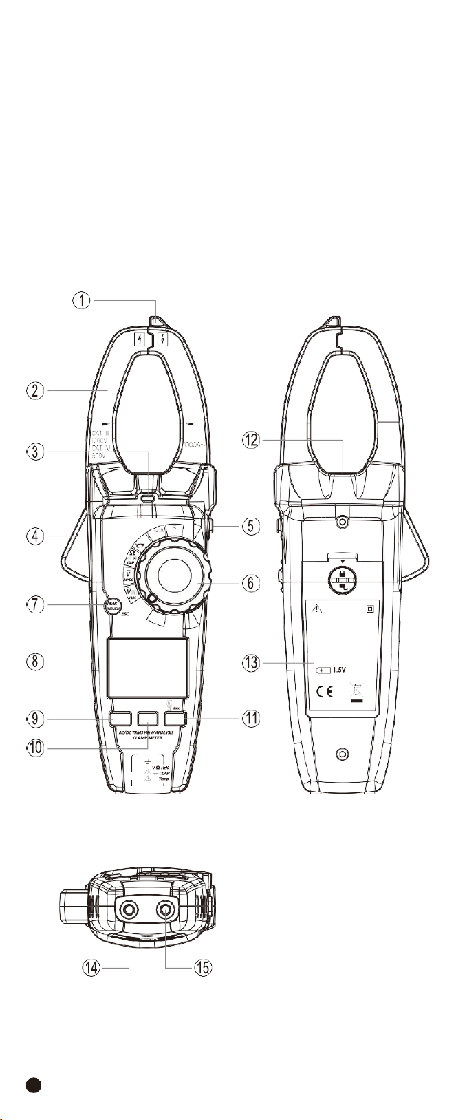
3.Description
3-1.Meter
Description
1-
NCV
Test
2-
Current
Clamp
3-
Non-Contact AC Voltage Indicator Light
4-Clamp Trigger
5-Data Hold/Flashlight Button
6-Rotary Function Swith
7-Peak/Inrush/ESC Button
8-LCD Display
9-F1 Button
10-F2 Button
11-F3 Button
12-Flashlight
13-Battery Cover
14-COM Input Jack
15-Positive
Input
Jack
1000A
W
Temp
OFF
V
Lo Z
WARNING
TO AVOID ELECTRICAL
SHOCK REMOVE TEST
LEADS BEFORE OPENING
CASE OR BATTERY COVER.
DO NOT OPERATE WITH
BATTERY COVER OPEN.
AAAX3
AUTO POWER OFF
F1 F2 F3
CAT III 1000V
CAT IV 600V
COM
7
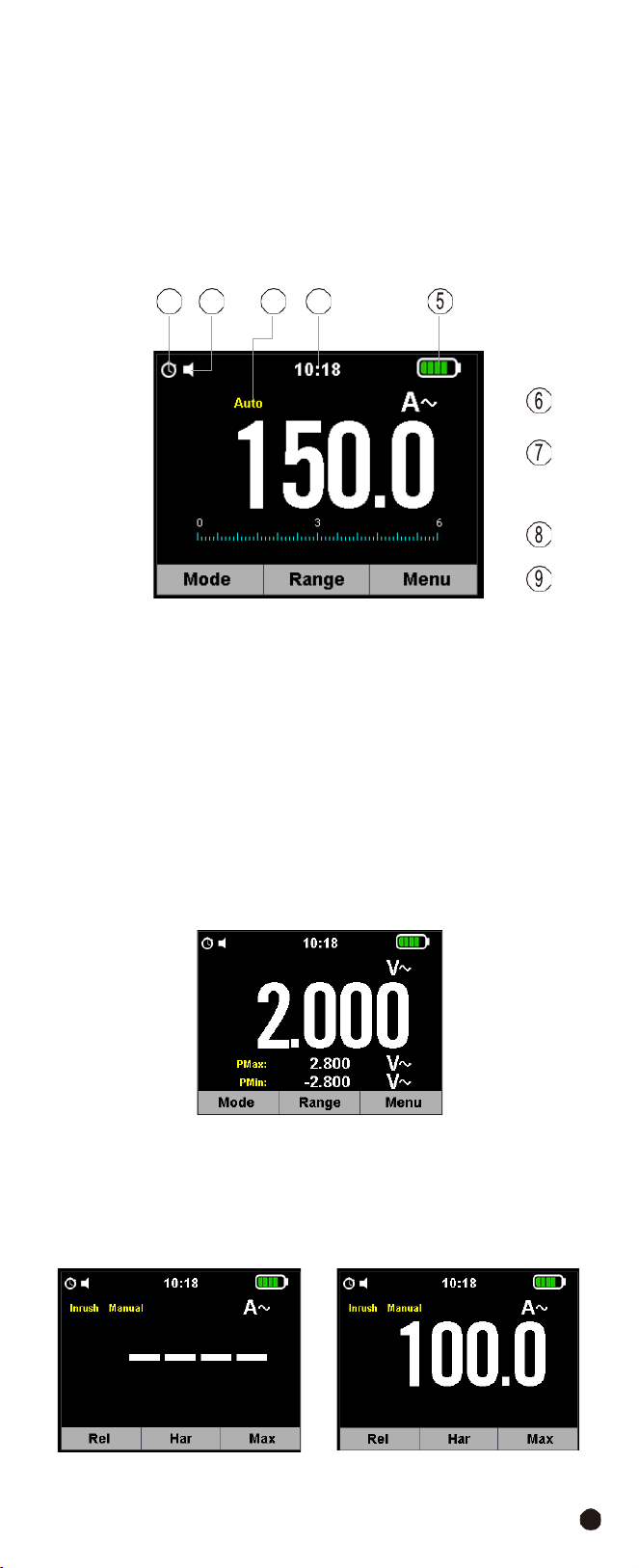
3-2.Display
Icons
Description
1-Auto Power Off
2-Key Beeper
3-Automatic/Manual Mode
4-System’s Time
5-
Battery
Capacity
6-
Measuring
Unit
7-
Measuring
Result
8-
Analogue
Bar
Graph
9-
Indications
Associated
with
Function
Keys
3-3.Description of Function Keys
3-3-1.Peak/Inrush/ESC Button
•
PEAK
Function
Note:
Only ACV functions can do the peak value measurement.
1.PEAK Key is the peak value measurement key that acts with trigger.
2.
In
ACV
functions,
press
the
Peak/Inrush/ESC
Button to activate the detection
of Maximum and Minimum peak values o AC Voltage with a response time of
1ms, both values are constantly updated and are displayed cyclically every time
the same key is pressed again.
3.
The display shows the symbol associated with the selected function: “PMAX”
for maximum peak value, “PMIN” for minimum peak value.
•
Inrush
Function
Note:
Only ACA functions can do the INRUSH value measurement.
1.Close motor and then install Jaw.
2.
Press the
Peak/Inrush/ESC
Button, “
---
”will
appear
in
the
display.
3.
Open
motor
and
then
read
the
value
on
the
display.
•
ESC
it
goes
back
to
a
normal
measuring
mode.
1 2
3 4
AC/DC
TRMS
H&W
ANALYSIS
CLAMP
METER
8
3-3-2.Data
Hold/Flashlight
Button
•
To
freeze
the
LCD
reading,
press
the
Data
Hold/Flashlight
Button.
•
While data hold is active, the HOLD icon appears on the LCD, press the
Data
Hold/Flashlight
Button again to return to normal operation.
•
Press and hold the
Data Hold/Flashlight
Button for more than 1 second to
turn the Flashlight on, press again to turn the Flashlight off.
3-3-3.F1,F2,F3
Software
Key
•
F1 Software Key: Default switch to MODE Function, AC POWER Function and
SAVE Button.
•
F2
Software
Key:
Default
into
RANGE
Button,
the
rotary
switch
function.
•
F3
Software
Key:
Default
into
Menu
Button.
9
3-4.Description of Internal Functions
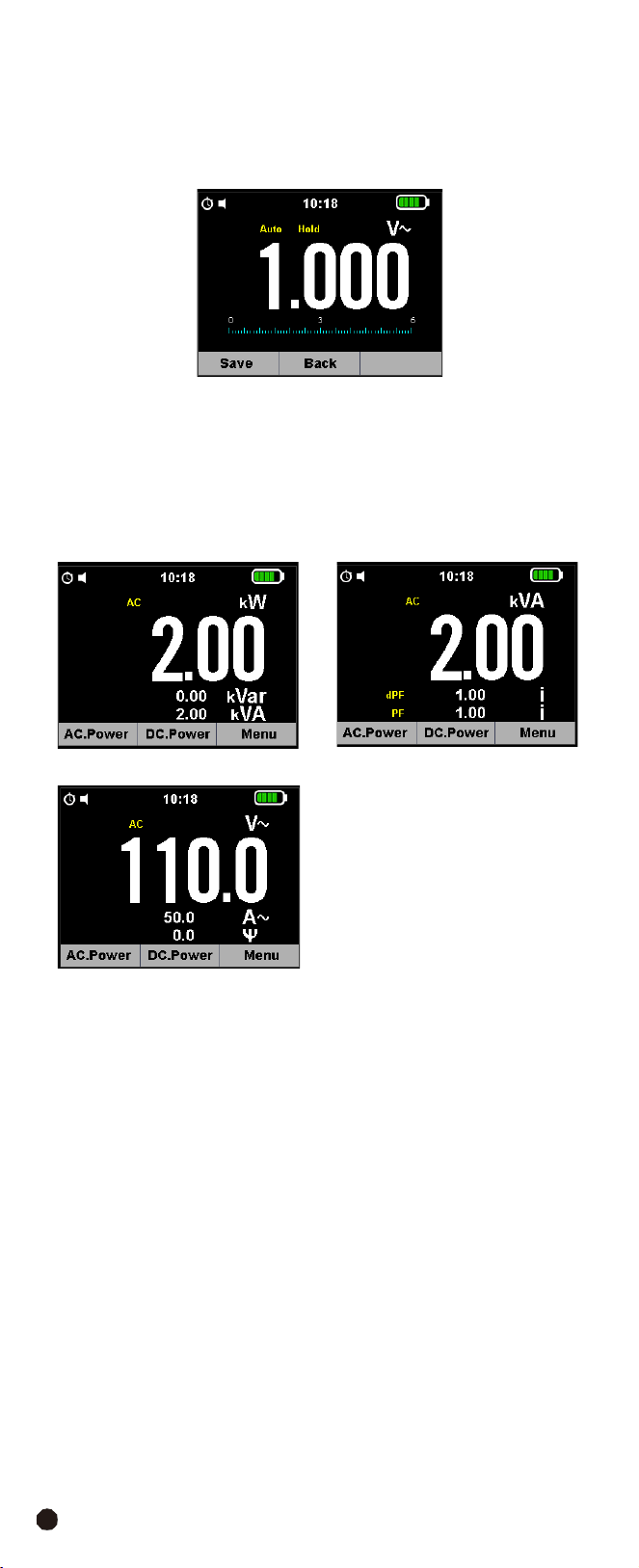
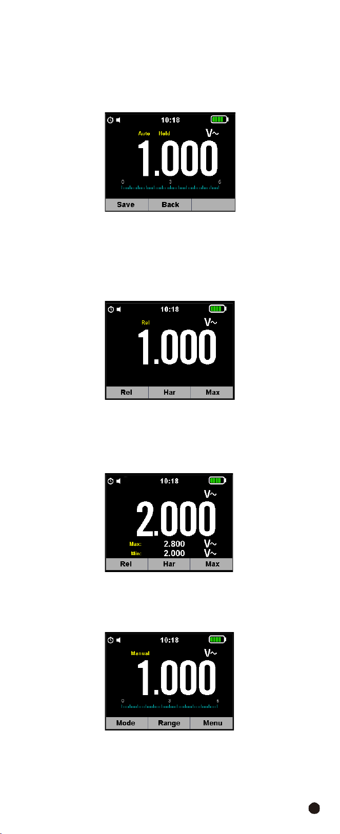
3-4-1.Save Function
1.
Press the
Data Hold/Flashlight
Button to freeze the result, the message
“
Hold
” appears on the display.
2.
Press
the
F1
(Save)
Key
to
save
the
data
in
the
instrument’s
memory.
3-4-2.Relative
Values
1.
To activate
the
relative mode, press and hold the
F3
Key for more than 2 second
to enter the selection interface.
2.
Press and hold the
F1
Key to enter relative measurement, the message REL
and symbol “
Rel
” appear on the display.
3-4-3.MIN/MAX Values
1.Press and hold the
F3
Key for more than 2 second to enter the selection interface.
2.Press the
F3
Key again to enter MAX MIN measurement, the message “Max”
and
symbol
“
MAX
MIN
”
appear
on
the
display.
3-4-4.Range
Function
1.
Into
manual
range
and
select
range
of
the
measure.
2.
If
pressing
the
Range
Button
for
greater
that
1
second
will
return
Auto
Range.
AC/DC
TRMS
H&W
ANALYSIS
CLAMP
METER
10
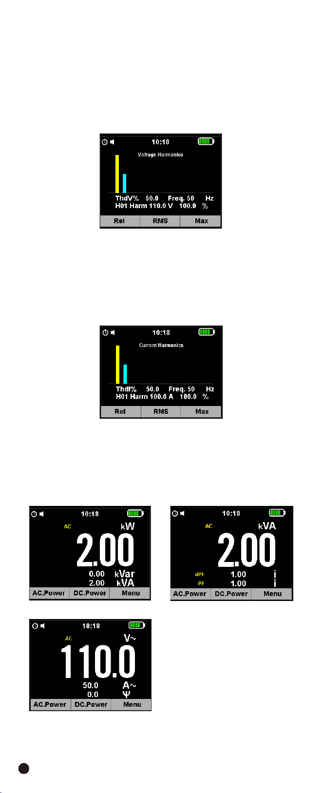
3-5.Individual Harmonic Measurement Function
3-5-1.Voltage Measurement Mode
1.
Press and hold the
F3
Button for more than 2 second to enter the selection
interface.
2.
Press
the
F2
(
Har
) Button to enter Harmonic Measurement, press the
F2
Button
again to go back.
3.
Press
the
F1
(
<<
)
and
F3
(
>>
)
Button
to
select
symbol
“H01~H25”.
3-5-2.Current
Measurement
Mode
1.
Press and hold the
F3
Button for more than 2 second to enter the selection
interface.
2.
Press
the
F2
(
Har
) Button to enter Harmonic Measurement, press the
F2
Button
again to go back.
3.
Press
the
F1
(
<<
)
and
F3
(
>>
)
to
select
symbol
“H01~H25”
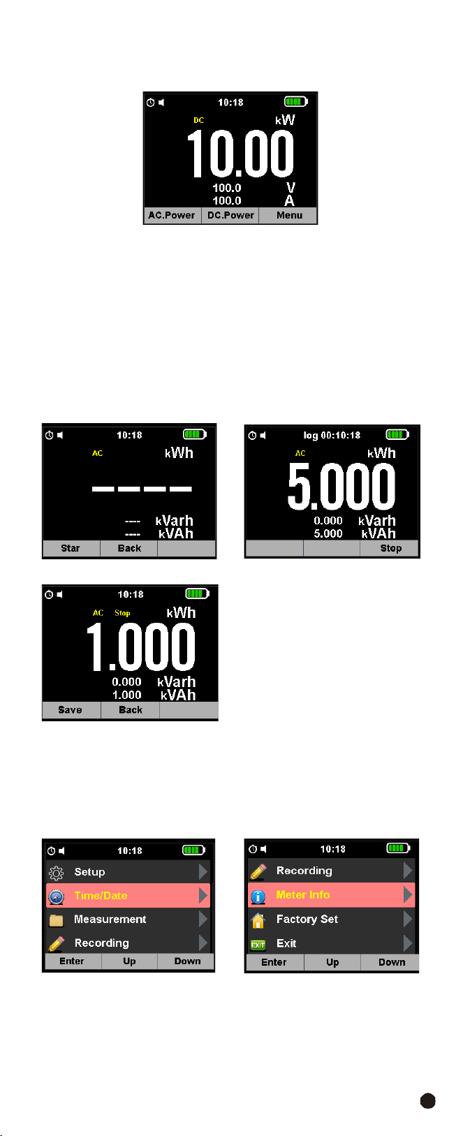
3-5-3.Power
Measurement
Mode
The AC power test interface is displayed by default, showing active power,
reactive power, and visual power.
1.
Press the
F1
Button access to power factors and displacement power factor
measurements, in the in-entry voltage, current and phase angle test interface.
11
2.
Press the
F2
Button to enter the DC Power test interface, which measures DC
Power, DC Current, DC Voltage.
3.
Press and hold the
F3
Button to enter the Harmonic Voltage Current Analysis
interface
of
power,
including
Voltage
Harmonic
Analysis
Maps,
Harmonic
Current
Analysis Maps and Electrical Energy Testing.
4.
Press the
F1
Button to enter the Current Harmonic Test.
5.Press
the
F2
Button
to
enter
the
Voltage
Harmonic
Test.
6.Press the
F3
Button to enter the Power Test, press the
F1
Button to start the
Clock, press the
F2
Button returns to the Previous Menu, press the
F3
Button
stops the Power Test, press the
F1
Button saves the test results again, press
the
F2
Button returns to the Previous Menu.
3-6.Main Menu
•
Press
the
F3
Button
to
enter
the
selection
interface.
•
Press the
F1
Button into selection menu, press the
F2
or
F3
Button to enter
the Installation Settings interface, which can set the Key Sound, Automatic
Shutdown Time, Time Display Format.
AC/DC
TRMS
H&W
ANALYSIS
CLAMP
METER
12
3-
7.SETUP
Press
the
F3
Button
to
enter
the
Installation
Settings
interface, you can set the
Key Sound, Automatic Shutdown Time, Time Format Switch.
•
Key
Sound:
Allows
activating/deactivating
the
tone
of
the
function
keys.
•
APO
Time:
Allows
defining
the
instrument’s
auto
power
off
interval
when
idling
in the five options: 15/30/45/60/OFF mins, Set value OFF to disable the function;
Press
the
F3
Button
to
switch
on
the
instrument
again
after
it
has
automatically
switched off.
•
12 Hour:
Allows defining the format of the system time between the options:
12 Hours ”On” and 24 Hours (Off).
3-
8.Time/Date
•
Press
the
F3
Button
to
enter
the
Settings
Interface.
•
Press
the
F2
and
F3
Button
to
select
the
Time
Setting
Mode
and
press
the
F1
Button
to
enter
the
Time
Setting.
3-
9.Measurement
Press the
F3
Button to enter the Settings Interface, press the
F2
and
F3
Button
to Select Mode.
3-9-1.Recall
Measurements
•
Press the
F1
Button to enter the data view, F1 deletes the data, F2 turns up, F3
turns down.
•
Press
the
ESC
Button
to
exit
the
view.
3-9-2.Delete
Measurements
•
Press the
F1
Button to enter the data view, F1 delete the data, F3 returns to
the Previous Menu.
•
Press
the
ESC
Button
to
exit
the
view.
13
3-9-3.Recall
Harmonics
•
Press the
F1
Button to enter the data view, F1 to delete the data, F2 to turn
the page up, F3 to enter the TREND Menu.
•
Press
the
ESC
Button
to
exit
the
view.
3-9-4.Delete
Harmonics
•
Press the
F1
Button to enter the data view, F1 delete the data, F3 returns to
the Previous Menu.
•
Press
the
ESC
Button
to
exit
the
view.
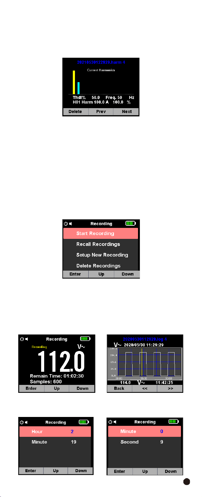
3-
10.Recording
•
Press the
F3
Button to enter the Settings Interface, press the
F2
and
F3
Button
selection
mode,
press
the
F1
Button to enter the Record Settings and Selection
Interface, press the
F1
Button to enter the Data Record, press the
F3
Button to
Stop, select the corresponding key to complete the corresponding operation.
•
Press
the
ESC
Button
to
return
to
exit.
3-10-1.Start
Recoring
Start
recording
with
F1
and
F3
Button
stop.
3-10-2.Recall
Recordings
Press the
F1
Button to enter the Viewing Interface,
F1
to enter the record trend
chart viewing interface,
F2
to turn up,
F3
to turn down the page.
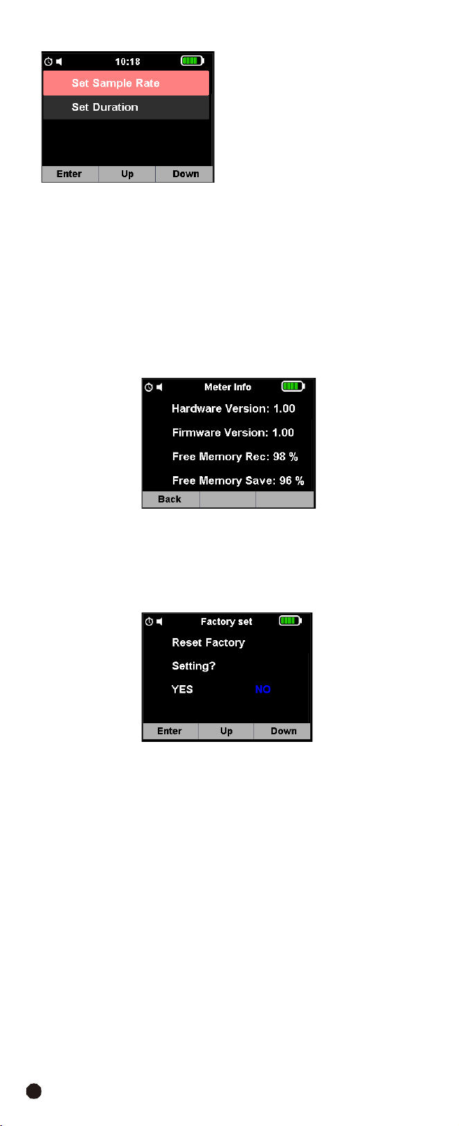
1.
Setup
New
Recording
Press
the
F1
Button
to
enter
the
record
installation
interface,
F2
up,
F3
down.
AC/DC
TRMS
H&W
ANALYSIS
CLAMP
METER
14
2.
Delete
Recordings
•
Press the
F1
Button to enter the Data View,
F1
delete the data,
F3
returns to
the Previous Menu.
•
Press
the
ESC
Button
to
exit
the
view.
3-11.Meter Info
•
Press the
F3
Button to enter the Instrument Information Interface,
F1
returns
to the Previous Menu.
•
Press
the
ESC
Button
to
exit.
3-12.Factory
Set
•
Press
the
F3
Button
to
enter
the
Instrument
Factory
Settings
Interface,
F1
OK,
F2
selection is,
F3
select NO.
•
Press
the
ESC
Button
to
exit.
15
4.Operation
Notes:
Read and understand all
WARNING
and
CAUTION
statements in this
operation manual prior to using this meter.
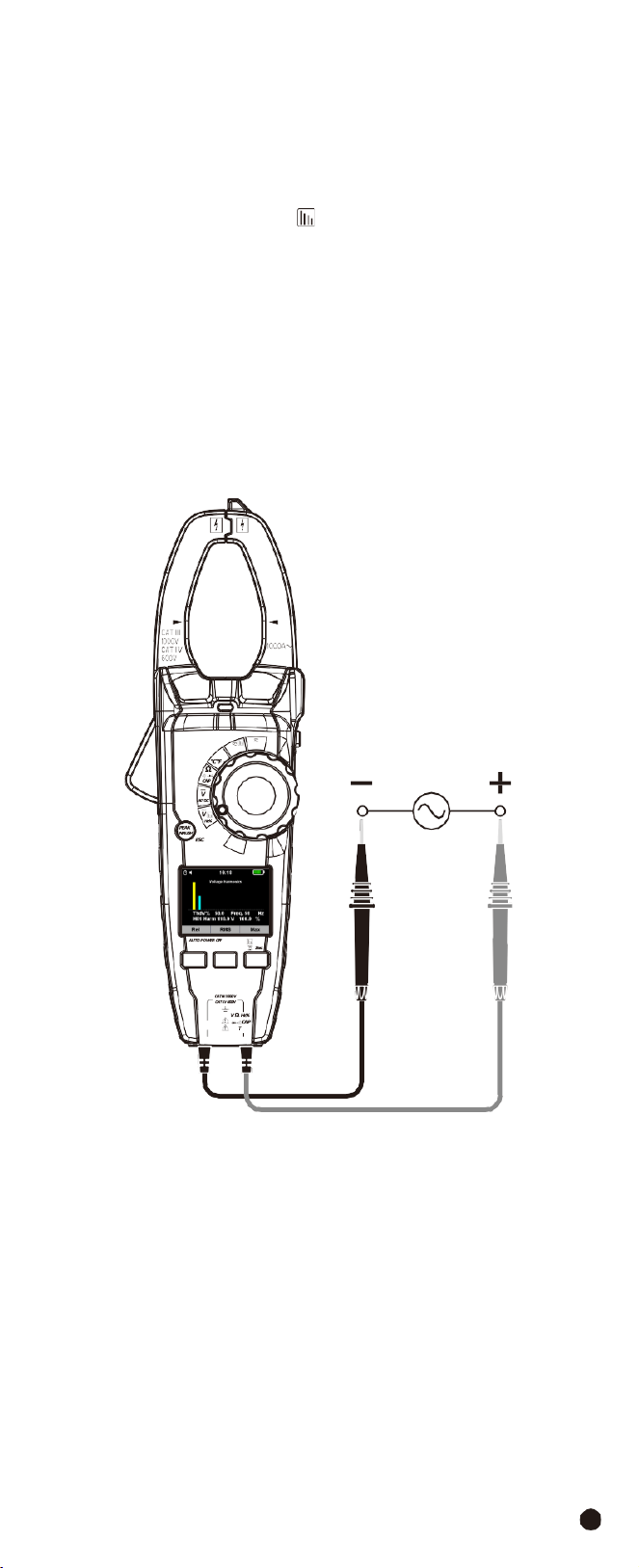
4-1.Individual
Harmonic
Voltage
Measurement
1.
Set the function switch to the
VAC
Hz%
Position.
2.
Insert the black test lead banana into the
COM
Input Jack; Insert the red test
lead banana into the
Positive
Input Jack.
3.
Press and hold the
F3
Button for more than 2 second to enter the selection
interface and press the
F2
(
Har
) Button to Enter Harmonic Measurement.
4.
Select the “
Hn
” indicator then press the
F1
and
F3
Button to enter the individual
harmonic mode.
5.
Connect the test leads in parallel to the circuit under test.
6.Read the Harmonic Voltage Measurement on the LCD display.
1000A
W
Temp
OFF
V
Lo Z
F1 F2 F3
AC/DC TRMS H&W ANALYSIS
CLAMP METER
COM
emp
AC/DC
TRMS
H&W
ANALYSIS
CLAMP
METER
16
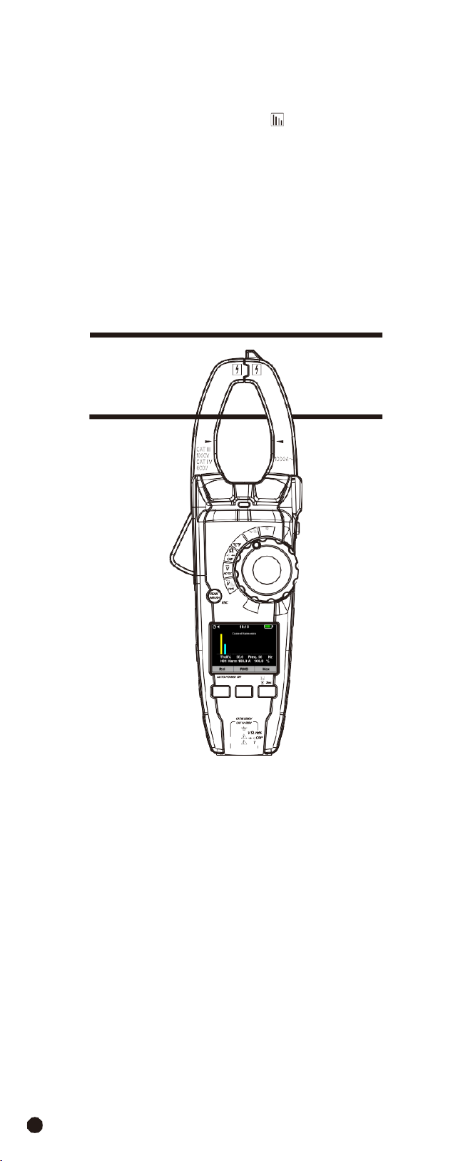
4-2.Individual
Harmonic
Current
Measurement
WARNING:
Ensure that the test leads are disconnected from the meter before
making current clamp measurements.
1.
Set the function switch to the
1000AAC/DC
Position.
2.
Press and hold the
F3
Button for more than 2 second to enter the selection
interface and press the
F2
(
Har
) Button to enter Harmonic Measurement.
3.
Select the “
Hn
” indicator then press the
F1
and
F3
Button to enter the individual
harmonic mode.
4.
Connect the test leads in parallel to the circuit under test.
5.Read the Harmonic Current Measurement on the LCD display.
Note:
The power measurement mode can also perform current harmonic
measurement analysis.
1000A
W
Temp
OFF
V
Lo Z
F1 F2 F3
AC/DC TRMS H&W ANALYSIS
CLAMP METER
COM
emp
17
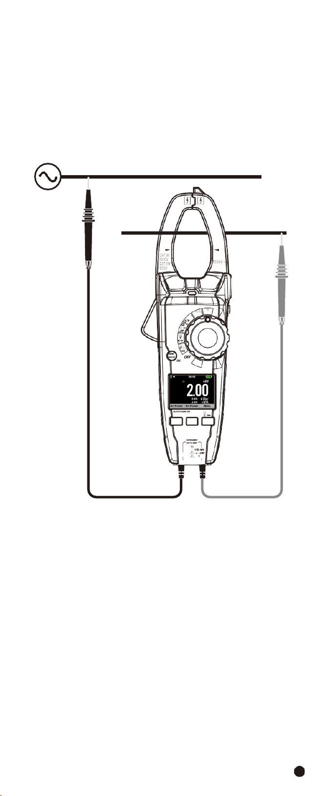
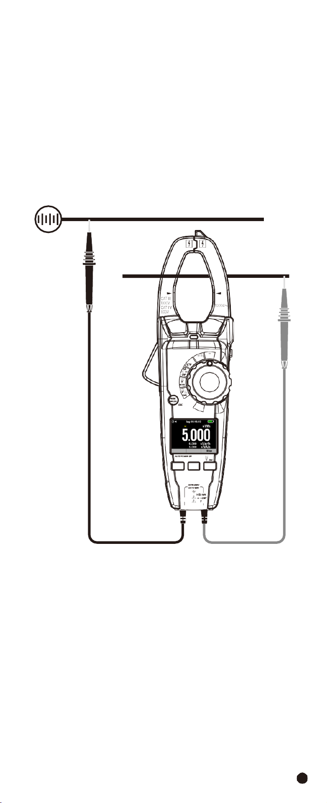
4-3.Measuring AC Power (Active, Apparent, Reactive)/Power Factor (PF)/
Displace Power Factor
1.
Set the rotary switch to the
W
Position.
2.
Insert the black test lead banana into the
COM
Input Jack; Insert the red test
lead banana into the
Positive
Input Jack.
3.
Press the trigger to open the transformer jaws and clamp one conductor only,
make sure that the jaw is firmly closed around the conductor.
4.
Using
the
F1
Button
to
choose
the
AC
Power
mode.
1000A
W
Temp
V
Lo Z
F1 F2 F3
AC/DC TRMS H&W ANALYSIS
CLAMP METER
COM
emp
AC/DC
TRMS
H&W
ANALYSIS
CLAMP
METER
18
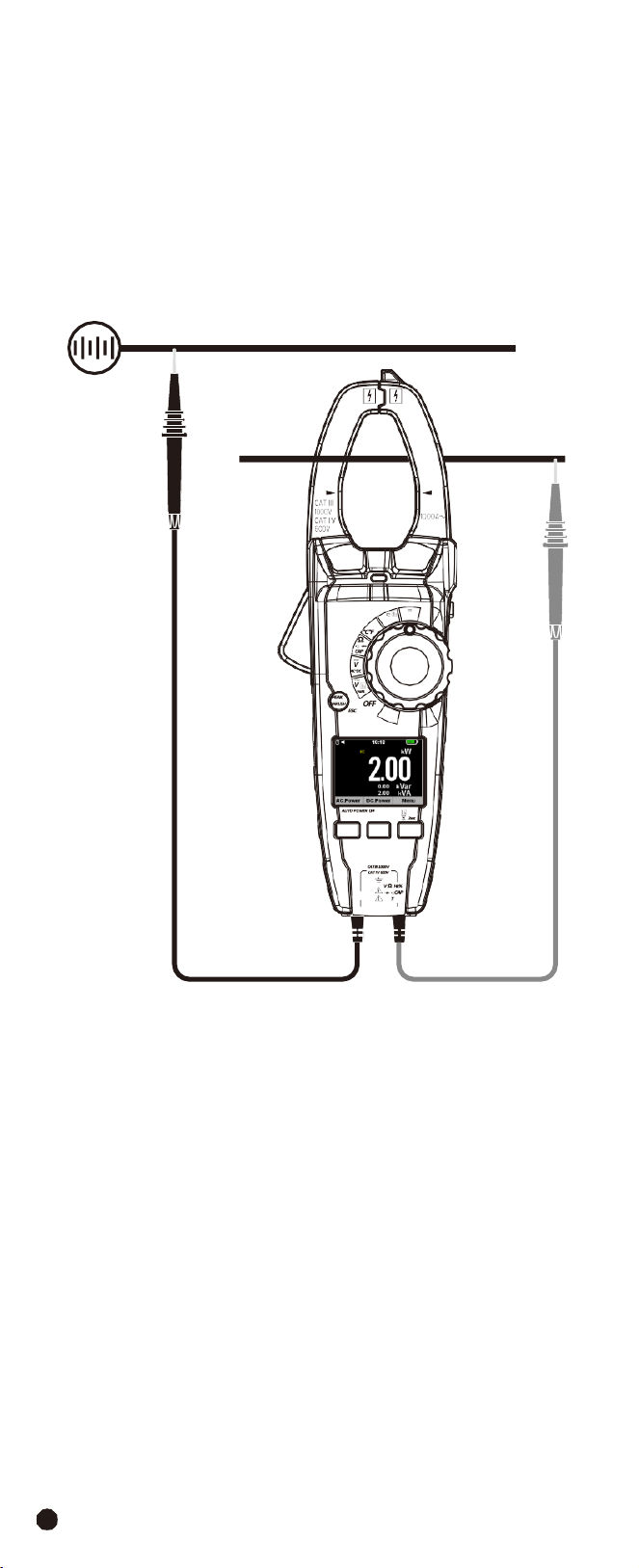
4-4.Measuring DC Power
1.
Set the rotary switch to the
W
Position.
2.
Insert the black test lead banana into the
COM
Input Jack; Insert the red test
lead banana into the
Positive
Input Jack.
3.
Press the trigger to open the transformer jaws and clamp one conductor only,
make sure that the jaw is firmly closed around the conductor.
4.
Using
the
F2
Button
to
choose
the
DC
Power
mode.
1000A
W
Temp
V
Lo Z
F1 F2 F3
AC/DC TRMS H&W ANALYSIS
CLAMP METER
COM
emp
19
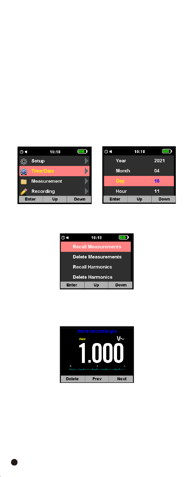
4-5.Energy
(Active,
Apparent,
Reactive)
1.
Set the rotary switch to the
W
Position.
2.
Insert the black test lead banana into the
COM
Input Jack; Insert the red test
lead banana into the
Positive
Input Jack.
3.
Press the trigger to open the transformer jaws and clamp one conductor only,
make sure that the jaw is firmly closed around the conductor.
4.
Using
the
F1
Button
to
choose
the
DC
Power
mode.
5.
Press and hold the
F3
Button for more than 2 second to Enter the selection
interface and press the
F3
Button to Enter Energy Measurement.
6.
Use the
F1
Button to select start,
F2
Button to select to return to the Previous
Menu.
1000A
W
Temp
OFF
V
Lo Z
F1 F2 F3
AC/DC TRMS H&W ANALYSIS
CLAMP METER
COM
emp
AC/DC
TRMS
H&W
ANALYSIS
CLAMP
METER
20
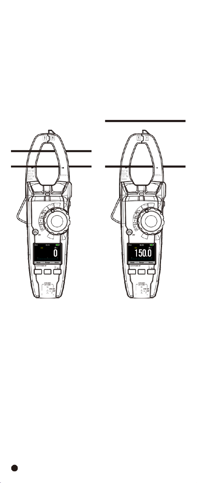
4-6.AC/DC Current Measurement
WARNING:
Ensure that the test leads are disconnected from the meter before
making current clamp measurements.
1.
Set
the
Function
Switch
to
the
1000AAC/DC
range.
2.
In
DC
Current mode Press the
F1
(
REL
) Button to zero the meter display.
3.Use the
F1
(
MODE
) Button to select AC or DC Current.
4.
Press the trigger to open jaw, fully enclose only one conductor for optimum
results, center the conductor in the jaw.
5.
The
clamp
meter
LCD
will
display
the
reading.
NO YES
1000A
W
Temp
OFF
V
Lo Z
F1 F2 F3
AC/DC TRMS H&W ANALYSIS
CLAMP METER
COM
emp
1000A
W
Temp
OFF
V
Lo Z
F1 F2 F3
AC/DC TRMS H&W ANALYSIS
CLAMP METER
COM
emp

21
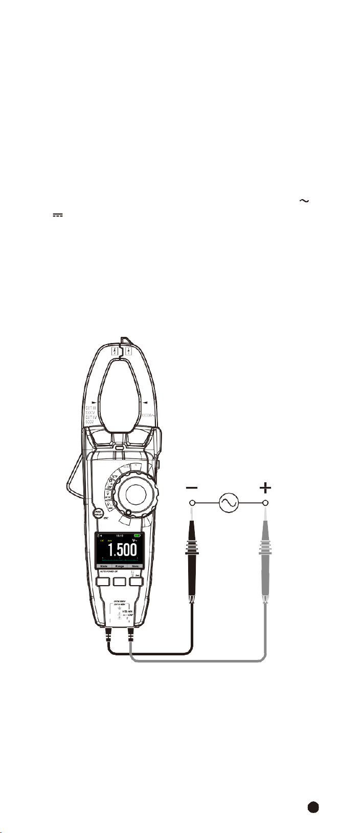
4-7.AC
Voltage
Measurement
1.
Set
the
rotary
switch
to
the
VAC
Position.
2.
Insert the black test lead banana into the
COM
Input Jack; Insert the red test
lead banana into the
Positive
Input Jack.
3.
Connect the test leads in parallel to the circuit under test.
4.Read the voltage measurement on the LCD display.
1000A
W
Temp
OFF
V
Lo Z
F1 F2 F3
AC/DC TRMS H&W ANALYSIS
CLAMP METER
COM
emp
AC/DC
TRMS
H&W
ANALYSIS
CLAMP
METER
22
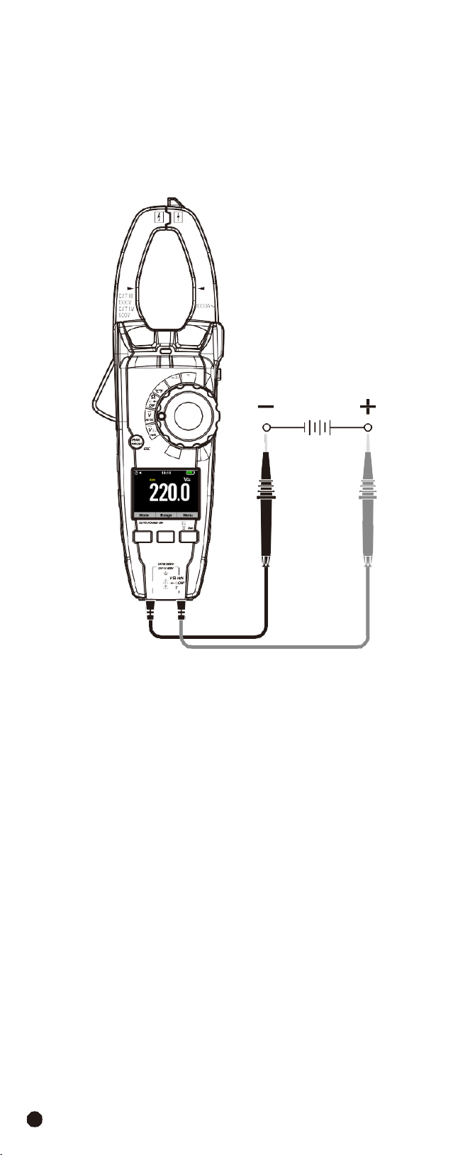
4-8.DC
(AC+DC)
Voltage
Measurement
1.
Set
the
rotary
switch
to
the
VDC
AC+DC
Position.
2.
Insert the black test lead banana into the
COM
Input Jack; Insert the red test
lead banana into the
Positive
Input Jack.
3.
Connect the test leads in parallel to the circuit under test.
4.Read the voltage measurement on the LCD display.
1000A
W
Temp
OFF
V
Lo Z
F1 F2 F3
AC/DC TRMS H&W ANALYSIS
CLAMP METER
COM
emp
23
4-9.Low
Z
Voltage
Measurement
WARNING:
Observe all safety precautions when working on live live voltages.
Do
not
connect
to
circuits
that
exceed
600V
AC/DC
when
the
meter
is
set
to
Low
Z.
•
Low
Z
is
used
to
check
for
“ghost”
voltage.
•
Ghost voltages are present when non-powered wires are in close proximity to
wires powered wires.
•
Capacitive coupling between wires make it appear that non-powered wires are
connected to a real source of voltage.
•
The
Low
Z setting places a load on the circuit, which greatly reduces the voltage
reading when connected to ghost voltage.
1.
Set
the
rotary
switch
to
the
V
Lo
Z
Position.
2.
Momentarily press the
MODE
Button to select AC or DC voltage, the AC “
”
or DC “
” symbol will appear on the LCD display.
3.
Insert the black test lead banana into the
COM
Input Jack; Insert the red test
lead banana into the
Positive
Input Jack.
4.
If measuring DC voltage, touch the red test lead to the positive side of the
circuit and the black test lead to the negative side of the circuit.
5.
Touch the test leads to the circuit under test.
6.Read the voltage on the LCD display.
1000A
W
Temp
OFF
V
Lo Z
F1 F2 F3
AC/DC TRMS H&W ANALYSIS
CLAMP METER
COM
emp
AC/DC
TRMS
H&W
ANALYSIS
CLAMP
METER
24
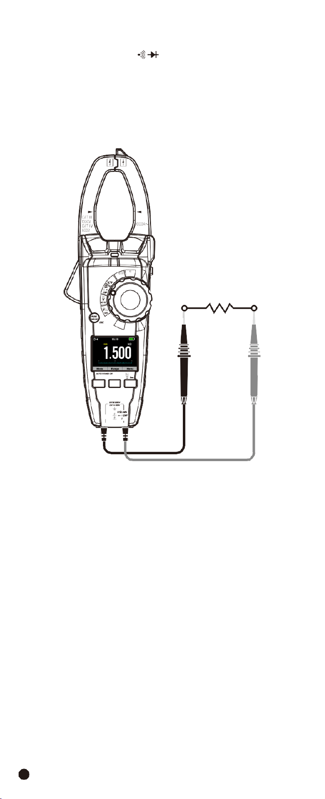
4-10.Resistance
Measurement
1.
Set the rotary switch to the
Ω
CAP
Position.
2.
Insert the black test lead banana into the
COM
Input Jack; Insert the red test
lead banana into the
Positive
Input Jack.
3.
Touch the test probe tips across the circuit or component under test.
4.Read the resistance on the LCD display.
1000A
W
Temp
OFF
V
Lo Z
F1 F2 F3
AC/DC TRMS H&W ANALYSIS
CLAMP METER
COM
emp
25
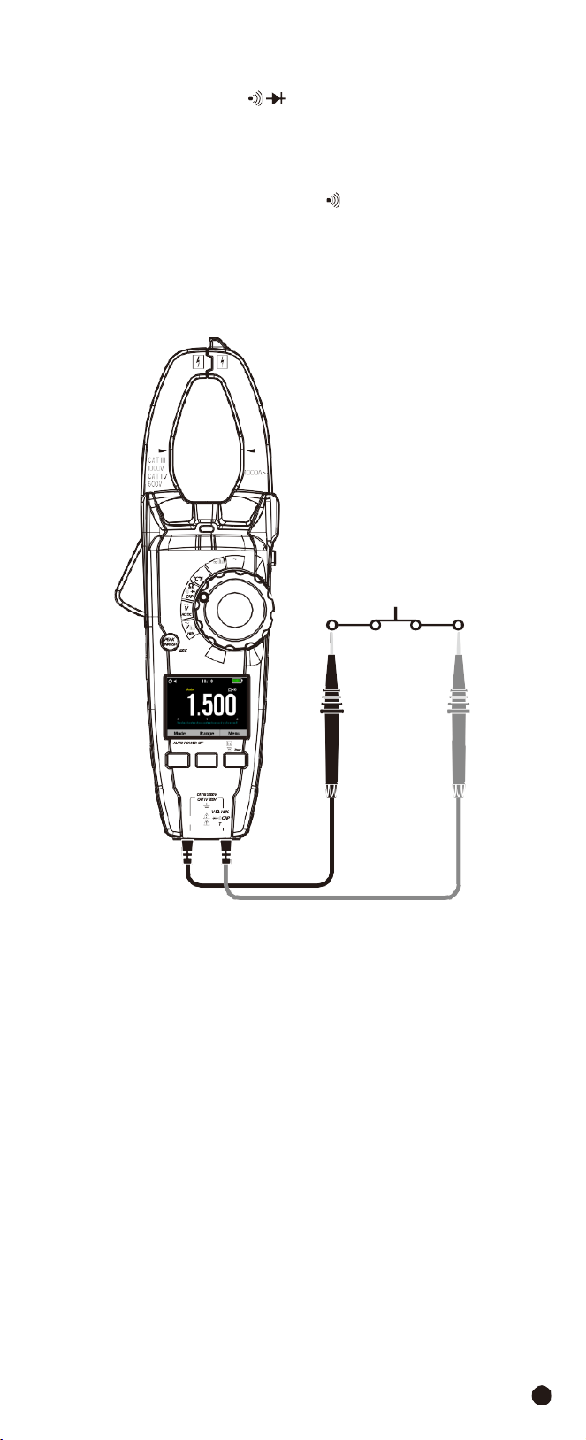
4-11.Continuity
Check
1.
Set the rotary switch to the
Ω
CAP
Position.
2.
Insert the black test lead banana into the
COM
Input Jack; Insert the red test
lead banana into the
Positive
Input Jack.
3.
Use the
MODE
Button to select continuity “
”, the display icons will change
when the
MODE
Button is pressed.
4.
Touch the test probe tips across the circuit or component under test.
5.If the resistance is < 50
Ω
, a tone will sound.
1000A
W
Temp
OFF
V
Lo Z
F1 F2 F3
AC/DC TRMS H&W ANALYSIS
CLAMP METER
COM
emp
AC/DC
TRMS
H&W
ANALYSIS
CLAMP
METER
26
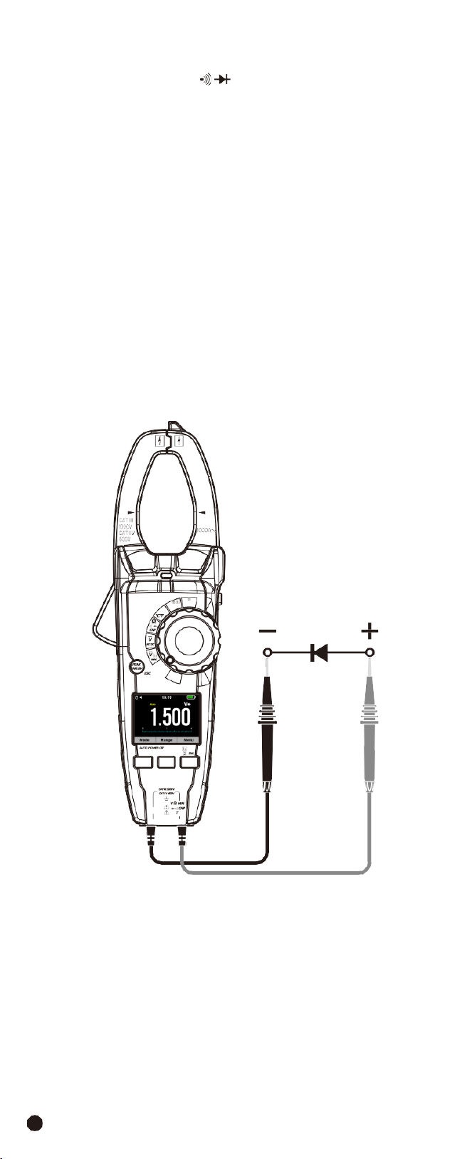
4-12.Diode Test
1.
Set the rotary switch to the
Ω
CAP
Position.
2.
Insert the black test lead banana into the
COM
Input Jack; Insert the red test
lead banana into the
Positive
Input Jack.
3.
Use the
MODE
Button to select the diode function if necessary (Diode symbol
will appear on the LCD when in Diode test mode).
4.
Touch the test probe tips to the diode or semiconductor junction under test,
note the meter reading.
5.
Reverse the test lead polarity by reversing the red and black leads, note this
reading.
6.
The
diode
or
junction
can
be
evaluated
as
follows:
•
If one reading displays a value (typically 0.400V to 0.900V) and the other reading
displays “
OL
”, the diode is good.
•
If
both
readings
display
“
OL
”
the
device
is
open.
•
If
both
readings
are
very
small
or
“
0
”,
the
device
is
shorted.
1000A
W
Temp
OFF
V
Lo Z
F1 F2 F3
AC/DC TRMS H&W ANALYSIS
CLAMP METER
COM
emp
27
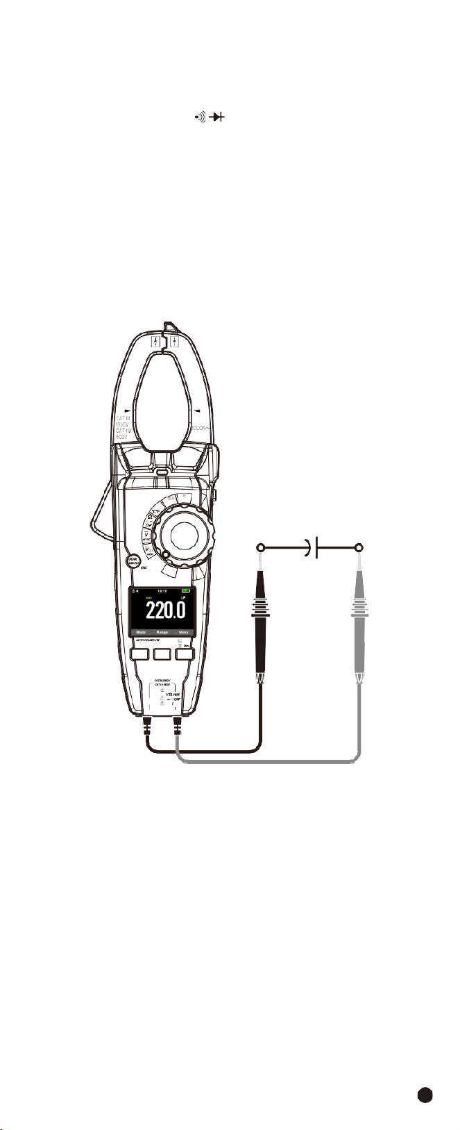
4-13.Capacitance
Measurement
WARNING:
To avoid electric shock, discharge the capacitor under test before
measuring.
1.
Set the rotary switch to the
Ω
CAP
Position.
2.
Insert the black test lead banana into the
COM
Input Jack; Insert the red test
lead banana into the
Positive
Input Jack.
3.
Touch the test probe tips across the part under test, if “
OL
” appears in the
display, remove and discharge the component.
4.
Read the capacitance value in the display, the display will indicate the proper
decimal point and value.
Note:
For very large values of capacitance measurement it can take several
minutes before the final reading stabilizes.
1000A
W
Temp
OFF
V
Lo Z
F1 F2 F3
AC/DC TRMS H&W ANALYSIS
CLAMP METER
COM
emp
AC/DC
TRMS
H&W
ANALYSIS
CLAMP
METER
28
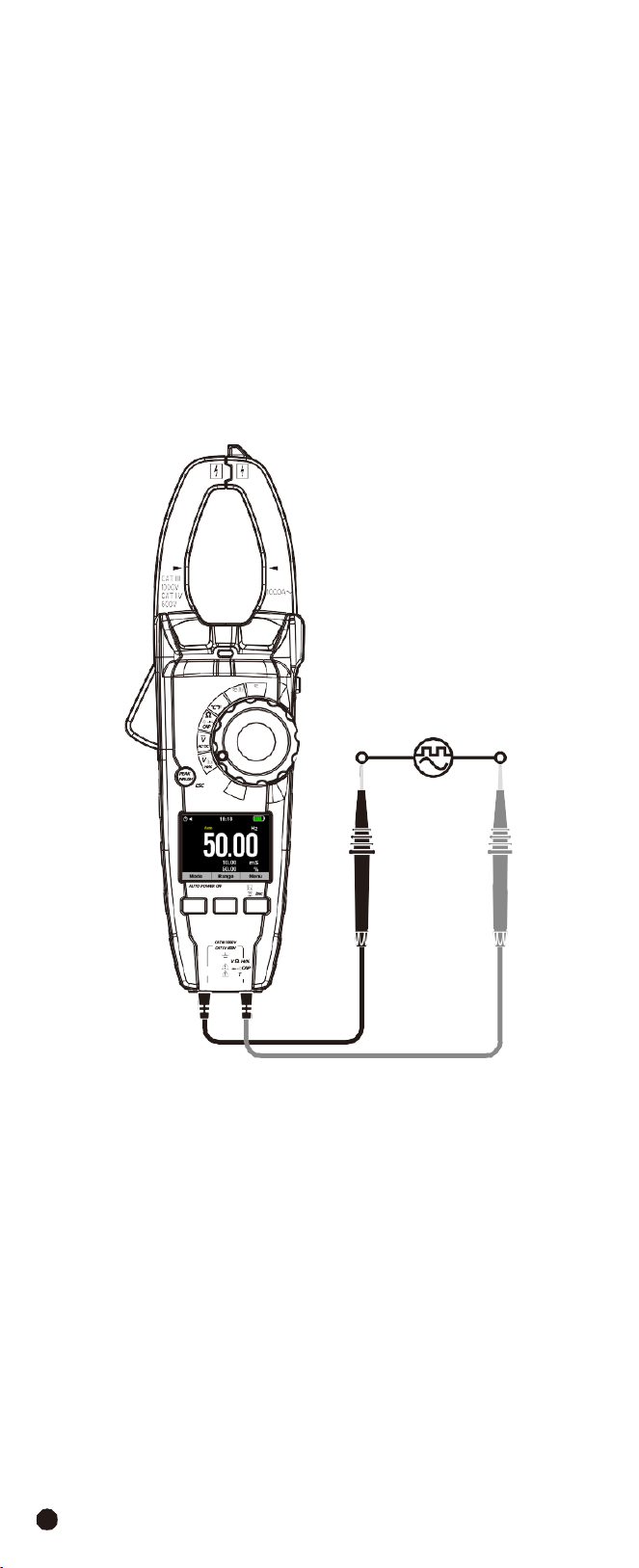
4-14.Frequency Measurement
WARNING:
To avoid electric shock, discharge the capacitor under test before
measuring.
1.
Set
the
rotary
switch
to
the
VAC
Hz%
Position.
2.
Insert the black test lead banana into the
COM
Input Jack; Insert the red test
lead banana into the
Positive
Input Jack.
3.
Press
Hz/%
Button to select the Frequency (
Hz
) or Duty cycle (
%
).
4.Touch the test probe tips across the part under test.
5.
Read the value on the display, the display will indicate the proper decimal point
and value.
6.
In Voltage and Current mode press
Hz/%
Button to select Frequency (
Hz
) or
Duty cycle (
%
).
1000A
W
Temp
OFF
V
Lo Z
F1 F2 F3
AC/DC TRMS H&W ANALYSIS
CLAMP METER
COM
emp
29
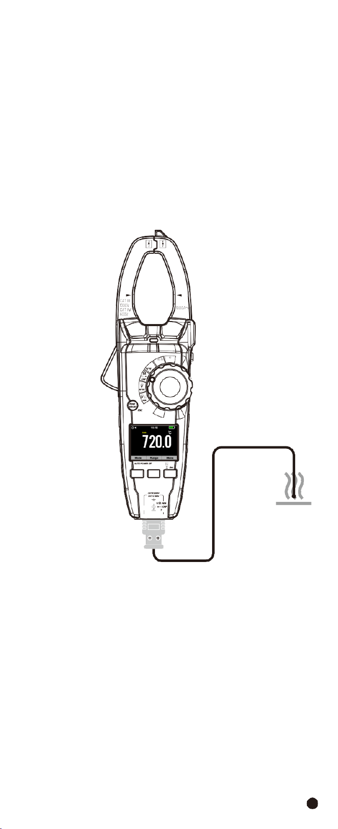
4-15.Temperature
Measurement
WARNING:
To avoid electric shock, be sure the thermocouple probe has been
removed before changing to another measurement function.
1.Set the function switch to the
TEMP
Position.
2.Use the
MODE
Button to select °C or °F.
3.
Insert the Temperature Probe into the negative
COM
and the
Positive
Input
Jack, observing polarity.
4.
Touch the Temperature Probe head to the device under test, continue to touch
the part under test with the probe until the reading stabilizes.
5.
Read the temperature on the display, the digital reading will indicate the proper
decimal point and value.
1000A
W
Temp
OFF
V
Lo Z
F1 F2 F3
AC/DC TRMS H&W ANALYSIS
CLAMP METER
COM
emp
AC/DC
TRMS
H&W
ANALYSIS
CLAMP
METER
30
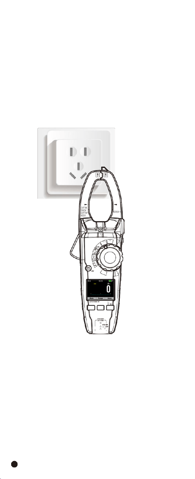
4-16.Non-Contact
AC
Voltage
Measurement
WARNING:
Risk of Electrocution. Before use, always test the Voltage Detector
on a known live circuit to verify proper operation.
1.
Touch the probe tip to the hot conductor or insert into the hot side of the
electrical outlet.
2.
If AC voltage is present, the detector light will illuminate.
Note:
The conductors in electrical cord sets are often twisted, for best results,
rub the probe tip along a length of the cord to assure placing the tip in close
proximity to the live conductor.
Note:
The detector is designed with high sensitivity, static electricity or other
sources of energy may randomly trip the sensor, this is normal operation.
1000A
W
Temp
OFF
V
Lo Z
F1 F2 F3
AC/DC TRMS H&W ANALYSIS
CLAMP METER
COM
emp

31
5.
Automatic
Power
OFF
•
In order to conserve battery life, the meter will automatically turn off after
approximately 15 minutes.
•
To turn the meter on again, turn the function switch to the
OFF
Position and
then to the desired function position.
6.
Maintenance
WARNING:
To avoid electrical shock, disconnect the meter from any circuit,
remove the test leads from the input terminals, and turn OFF the meter before
opening the case. Do not operate the meter with an open case.
6-1.Cleaning
and
Storage
•
Periodically
wipe
the
case
with
a
damp
cloth
and
mild
detergent.
•
Do
not
use
abrasives
or
solvents.
•
If the meter is not to be used for 60 days or more, remove the battery and store
it separately.
6-2.Battery Replacement
1.Remove the Phillips head screw that secures the rear battery door.
2.Open the battery compartment.
3.Replace the 3x1.5V AAA Akline batteries.
4.Secure the battery compartment.
6-3.Temperature
Probe
Replacement
Note:
To use a Type K thermocouple probe that is terminated by a subminiature
(Flat blade) connector, a subminiature-to-banana plug adaptor is required.
AC/DC
TRMS
H&W
ANALYSIS
CLAMP
METER
32
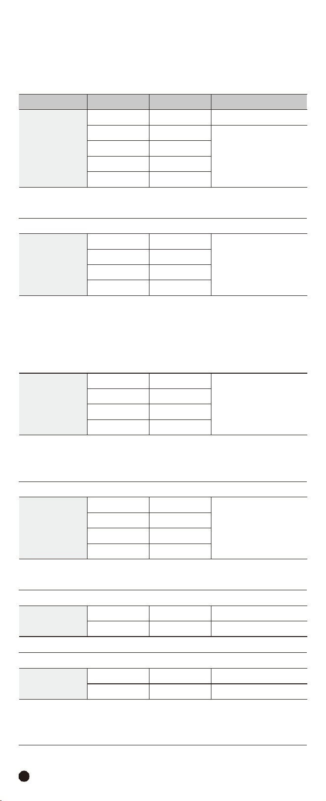
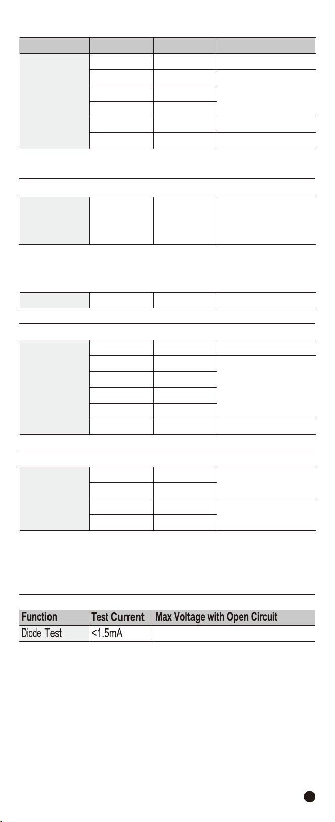
7.Specifications
7-1.Technical
Specifications
Accuracy
calculated
as
[%reading
+
(num.
digits*resolution)]
at
18
to
28°C;
<75%HR.
Function
Range
Resolution
Accuracy
DC
Voltage
600.0mV
0.1mV
±(0.5%
+
8
digits)
6.000V
0.001V
±(1.5%
+
5
digits)
60.00V
0.01V
600.0V
0.1V
1000V
1V
Input
impedance:
>10M
Ω
Protection
against
overcharge:
1000VDC/ACrms
AC TRMS Voltage
(50Hz-400Hz)
6.000V
0.001V
±(1.5%
+
5
digits)
60.00V
0.01V
600.0V
0.1V
1000V
1V
Input
impedance:
>9M
Ω
Protection
against
overcharge:
1000VDC/ACrms
Accuracy specified from 5% to 100% of the measuring range, sine wave.
Accuracy PEAK function: ±10%rdg, PEAK response time: 1ms.
Low
Z
AC
TRMS
Voltage
6.000V
0.001V
±(3.0%
+
40
digits)
60.00V
0.01V
600.0V
0.1V
1000V
1V
Input
impedance:
3k
Ω
Protection
against
overcharge:
1000VDC/ACrms
Accuracy
specified
from
5%
to
100%
of
the
measuring
range,
sine
wave.
AC+DC
TRMS
Voltage
(50Hz-1kHz)
6.000V
0.001V
±(2.5%
+
20
digits)
60.00V
0.01V
600.0V
0.1V
1000V
1V
Input
impedance:
>10M
Ω
Protection
against
overcharge:
1000VDC/ACrms
DC
Current
600.0A
0.1A
±(2.5%
+
5
digits)
1000A
1A
±(2.8%
+
5
digits)
Protection
against
overcharge:
1000ADC/ACrms
AC
TRMS
Current
600.0A
0.1A
±(2.5%
+
8
digits)
1000A
1A
±(2.8%
+
8
digits)
Protection
against
overcharge:
1000ADC/ACrms
Accuracy specified from 5% to 100% of the measuring range, sine wave.
Accuracy Inrush function integral time 100ms, and reading for reference only.
33
Function
Range
Resolution
Accuracy
Resistance and
Continuity
Test
600.0
Ω
0.1
Ω
±(1.0%
+
10
digits)
6.000k
Ω
0.001k
Ω
±(1.5%
+
5
digits)
60.00k
Ω
0.01k
Ω
600.0k
Ω
0.1k
Ω
6.000M
Ω
0.001M
Ω
±(2.5%
+
5
digits)
60.00M
Ω
0.01M
Ω
±(3.5%
+
10
digits)
Buzzer:
<50
Ω
Protection
against
overcharge:
1000VDC/ACrms
Frequency
(Electronic
Circuits)
9.999-
9.99kHz
0.01-
10Hz
±(1.2%
+
5
digits)
Protection against overcharge: 1000VDC/ACrms
Sensitivity: >5Vrms (at 20%-80% duty cycle)
Duty
Cycle
10.0%-
90.0%
0.1%
±(1.2%
+
8
digits)
Pulse
frequency
range:
40Hz-10kHz;
Pulse
amplitude:
±5V
(100s-100ms)
Capacity
60.00nF
0.01nF
±(4.0%
+
20
digits)
600.0nF
0.1nF
±(3.0%
+
8
digits)
6.000µF
0.001µF
60.00µF
0.01µF
600.0µF
0.1µF
6000µF
1µF
±(5.0%
+
8
digits)
Protection
against
overcharge:
1000VDC/ACrms
Temperature with
K-Type Probe
-40.0
to
600.0°C
0.1°C
±(1.5%
+
3°C)
600
to
1000°C
1°C
-40.0
to
600.0°F
0.1°F
±(1.5%
+
5.4°C)
600
to
1800°F
1°F
Protection
against
overcharge:
1000VDC/ACrms
Instrument accuracy without probe; Specified accuracy with stable environmental
temperature at ±1°C.
For
long-lasting
measurements,
reading
increases
by
2°C.
3.3VDC
AC/DC
TRMS
H&W
ANALYSIS
CLAMP
METER
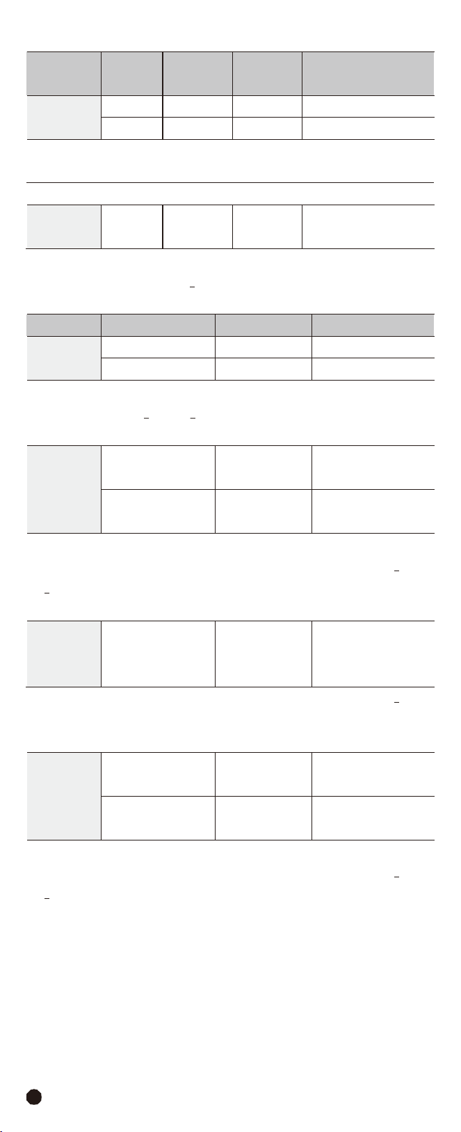
34
Function
Harmonic
Orde
Base
Wave
Frequency
Resolution
Accuracy
Voltage
Harmonics
1-
25
20-
75Hz
0.1%
THD
±(5.0%
+
8
digits)
1-
8
75-
400Hz
0.1%
THD
±(6.0%
+
8
digits)
Protection
against
overcharge:
1000VDC/ACrms
Uncertainty
defined
for:
Voltage
>10V;
Below
2%
of
voltage
range,
add
20
counts.
Current
Harmonics
1-
25
20-
75Hz
0.1%
THD
±(5.0%
+
20
digits)
Protection
against
overcharge:
1000ADC/ACrms
Uncertainty
defined
for:
Current
>10A;
Below
2%
of
current
range,
add
20
counts.
Function
Range
Resolution
Accuracy
DC
Power
0.00-
99.99kW
0.01kW
±(3.0%
+
10
digits)
100.0-
999.9kW
0.1kW
±(3.0%
+
5
digits)
Protection
against
overcharge:
1000VDC/ACrms
Voltage
>10V;
Current
>10A;
Pf
>0.5;
Below
2%
of
range,
add
20
counts.
AC Power
(Active,
Apparent,
Reactive)
0.00-
99.99
kW/kVA/kVAR
0.01
kW/kVA/kVAR
±(3.0%
+
10
digits)
100.0-
999.9
kW/kVA/kVAR
0.1
kW/kVA/kVAR
±(3.0%
+
5
digits)
Protection
against
overcharge:
1000VDC/ACrms
Uncertainty defined for: Sine waveform 20-75Hz; Voltage >10V; Current >10A;
Pf >0.5; Below 2% of range, add 20 counts.
Power
Factor/
Displace
Power
Factor
0.20-
1.00
0.01
±3°
Uncertainty defined for: Sine waveform 20-75Hz; Voltage >10V; Current >10A;
Below 2% of voltage and current range, add 2°.
Energy
(Active,
Apparent,
Reactive)
0.000-
9.999
kW/kVA/kVAR
0.001
kW/kVA/kVAR
±(3.0%
+
10
digits)
10.00-
99.99
kW/kVA/kVAR
0.01
kW/kVA/kVAR
±(3.0%
+
5
digits)
Protection against
overcharge: 1000VDC/ACrms
1000ADC/ACrms
Uncertainty defined for: Sine waveform 20-75Hz; Voltage >10V; Current >10A;
Pf >0.5; Below 2% of range, add 20 counts.

35
7-2.General
Specifications
Clamp
Jaw
Opening
Display
Low Battery Indication
Over-Range Indication
Measurement Rate
PEAK
INRUSH
Temperature
Sensor
Input Impedance
AC Response
1.26” (33mm) approx.
6000 counts RGB
LCD
“
”
is displayed
Over-range indication “OL” display
3 readings per second, nominal
Captures peaks >1ms
100ms
Type K thermocouple
10M
Ω
(VDC
and
VAC)
True
rms
(AAC
and
VAC)
Operating
Temperature
5
to
40°C
(41
to
104°F)
Storage
Temperature
Operating Humidity
Storage Humidity
Operating Altitude
Battery
Auto Power Off
Dimensions & Weight
Safety
-20 to 60°C (-4 to 140°F)
Max 80% up to 31°C (87°F) decreasing linearly to 50%
at 40°C (104°F)
<80%
2000 meters (7000ft.) maximum.
Three 1.5 AAA Akline Batteries
After approx. 15 minutes
239x80x49mm; 350g
CAT
IV
600V,
CATIII
1000V
Conforms
to
UL
STD.
61010-1,
61010-2-030,
61010-2-033
and
61010-031;
Certified to CSA STD. C22.2, NO.61010-1, 61010-2-30,
61010-2-033 and 61010-031.

Warranty
Triplett / Jewell Instruments extends the following warranty to the original
purchaser of these goods for use. Triplett warrants to the original purchaser
for use that the products sold by it will be free from defects in workmanship
and material for a period of (1) one year from the date of purchase. This
warranty does not apply to any of our products which have been repaired or
altered by unauthorized persons in any way or purchased from unauthorized
distributors so as, in our sole judgment, to injure their stability or reliability,
or which have been subject to misuse, abuse, misapplication, negligence,
accident or which have had the serial numbers altered, defaced, or
removed. Accessories, including batteries are not covered by this warranty.
Copyright © 2023 Triplett
www.triplett.com
AC/DC
TRMS
H&W
ANALYSIS
CLAMP
METER