Loading ...
Loading ...
Loading ...
16
8. Testrun
Fig.8-6
9. Systemcontrol
Refer to the outdoor unit installation manual.
A Watersupplypump
B Water(about1000cc)
C Drain plug
D Pourwaterthroughoutlet
• Becarefulnottospraywaterinto
the drain pump mechanism.
1
2 3
Whenequippedwiththesignalreceiver
Whenequippedwiththei-Seesensor
4 6 5 7
Whenequippedwiththewirelessremotecontroller
8 9
0 1
10. Installingthegrille
Fig.10-1
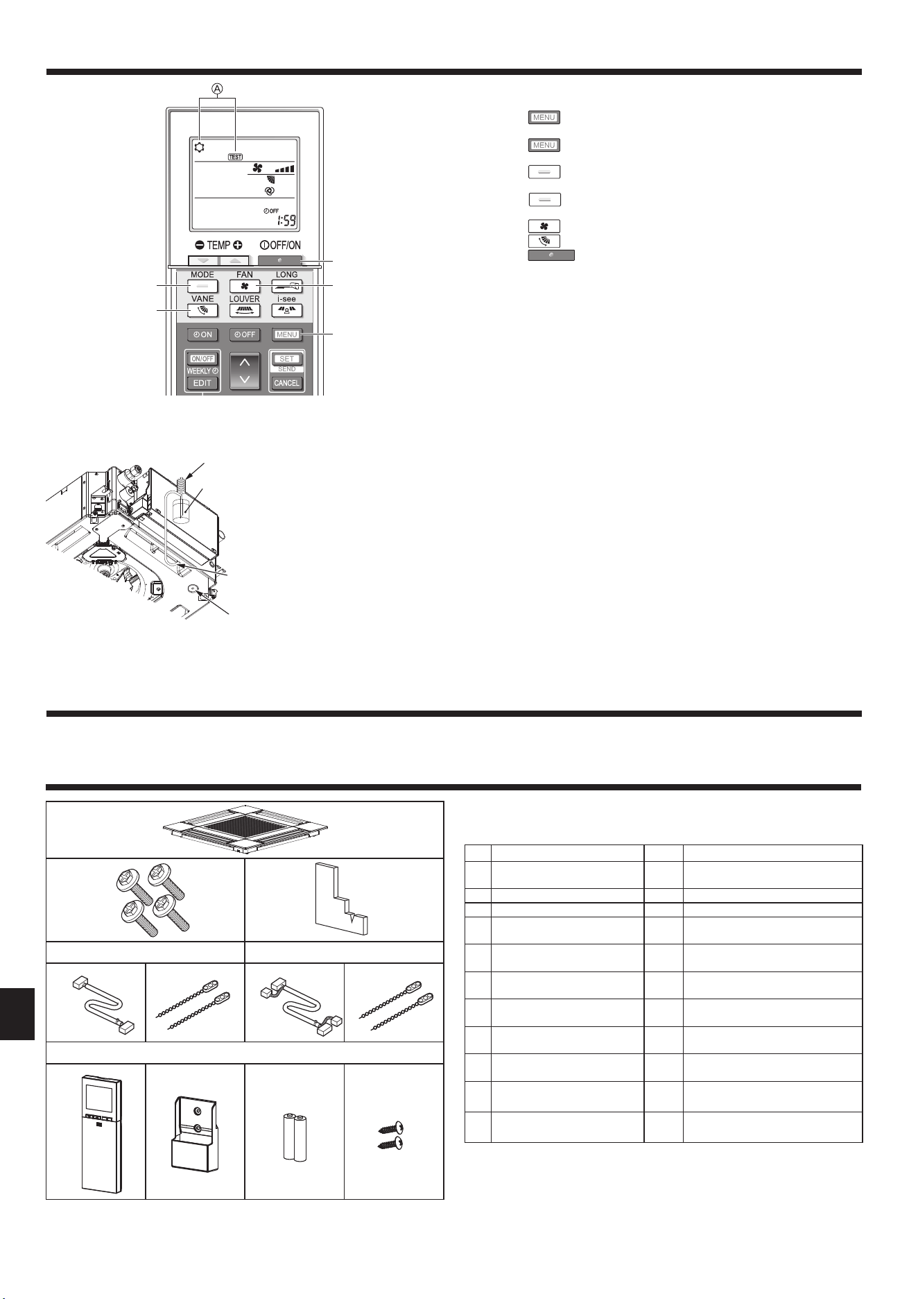
10.1. Checkthegrilleaccessories(Fig.10-1)
• Thegrilleshouldbesuppliedwiththefollowingaccessories.
Accessoryname Q’ty Remark
1
Grille 1
625 × 625 (mm), 24-19/32 × 24-
19/32(in)
2
Screw with washer 4 M5×0.8×25(mm)
3
Gauge 1
4
Junction wire for signal re-
ceiver
1
Included when equipped with the
signalreceiver.
5
Junctionwirefori- Seesensor 1
Included when equipped with the
i-Seesensor.
6
Fastener 2
Included when equipped with the
signalreceiver.
7
Fastener 2
Included when equipped with the
i-Seesensor.
8
Wirelessremotecontroller 1
Included when equipped with the
wireless remote controller.
9
Remote controller holder 1
Included when equipped with the
wireless remote controller.
0
LR6AAbatteries 2
Included when equipped with the
wireless remote controller.
1
3.5 × 16 mm tapping screws 2
Included when equipped with the
wireless remote controller.
2
5
3
1
4
8.2.2. Usingthewirelessremotecontroller
1. Turn on the power to the unit at least 12 hours before the test run.
2. Pressthe
button 1for5seconds.(Fig.8-5)
(Performthisoperationwhentheremotecontrollerdisplayisturnedoff.)
3. Pressthe
button 1.
A[TEST]andthecurrentoperationmodearedisplayed.(Fig.8-5)
4. Pressthe
button 2toactivatecoolmode,thencheckwhethercoolairis
blown out from the unit.
5. Pressthe
button 2toactivateheatmode,thencheckwhetherwarmair
is blown out from the unit.
6. Pressthe
button 3 and check whether the fan speed changes.
7. Pressthe
button 4andcheckwhethertheautovaneoperatesproperly.
8. Pressthe
button 5 to stop the test run.
(Aftertwohours,asignalwillbesenttostopthetestrun.)
Note:
• Pointtheremotecontrollertowardstheindoorunitreceiverwhilefollowing
steps3to8.
• ItisnotpossibletoperformthetestruninFAN,DRY,orAUTOmode.
Fig.8-5
B
D
A
C
8.3. Self-check
■ Refertotheinstallationmanualthatcomeswitheachremotecontrollerfor
details.
8.4. Checkofdrainage(Fig.8-6)
• Ensurethatthewaterisbeingproperlydrainedoutandthatnowaterisleaking
fromjoints.
Whenelectricworkiscompleted.
• Pourwaterduringcoolingoperationandcheck.
Whenelectricworkisnotcompleted.
• Pourwaterduringemergencyoperationandcheck.
* Drainpumpandfanareactivatedsimultaneouslywhensinglephase230V
isturnedontoS1and S2 on terminal block after the connector (SWE) on
controllerboardintheelectricalcomponentboxissettoON.
Be sure to turn it back to the former state after work.
Loading ...
Loading ...
Loading ...