1
3
2
4
65
Note:
The module-connec�ng interface is used to connect other func�on module, such as KD8003 series door
station, DS-KD-TD(M/E), DS-KD-KP, etc.
Note:
We highly recommend you use an external power supply (12 V, 2 A).
Appearance
Terminal
1
1
2
A1
A2
A3
A4
485-: Module-connec�ng Interface (Input)
B1
B2
B3
B4
3
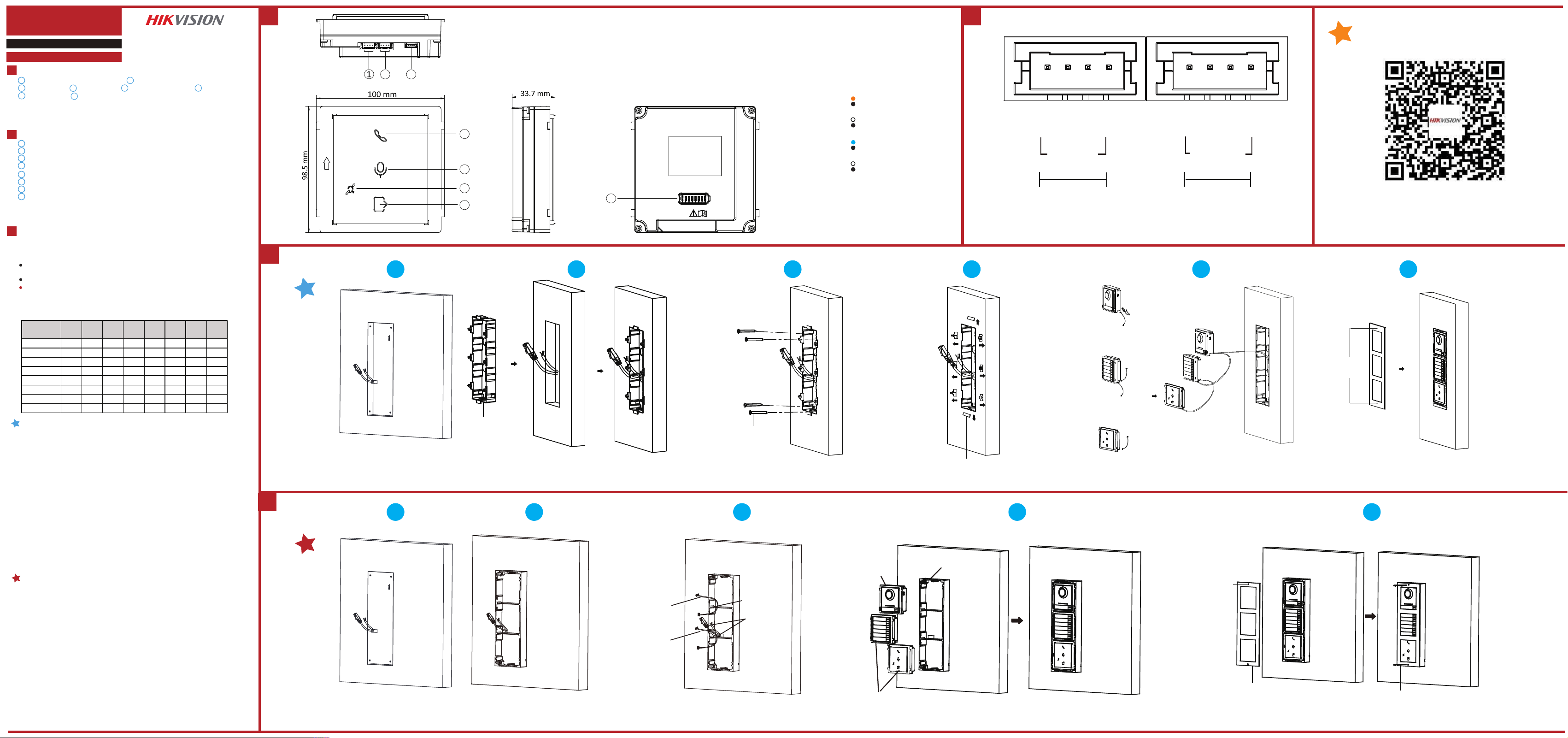
Note: Video intercom module door sta�on support two-module installa�on, three-module installa�on,
four-module installa�on and six module installa�on. Here takes three-module installa�on as an example.
Installation
Tools that you need to prepare for installa�on: Drill(6), cross screw driver (PH1*150
mm), and gradienter.
Make sure all the related equipment is power-o during the installa�on.
Make sure you have congured the sub module address before installa�on. Valid sub
module address range is 1 to 8. The No. should be unique for sub modules that
connected to the same main unit. The sub module address and corresponding switch
status is shown as the gure.
Before You Start
13
13
2
485+: Module-connec�ng Interface (Input)
12V IN: Module-connec�ng Interface (Input)
GND: Module-connec�ng Interface (Input)
485-: Module-connec�ng Interface (Output)
485+: Module-connec�ng Interface (Output)
12V IN: Module-connec�ng Interface (Output)
GND: Module-connec�ng Interface (Output)
UD30510B
Diagram References
2
3
4
5
6
7
8
Module-connec�ng Interface (Output)
Module-connec�ng Interface (Input)
Debugging Port
7
Unlock Indicator
Calling Indicator
8
DIP Switch
Two-way Audio Indicator
PMR Indicator
Calling Indicator
Solid Yellow: Calling
Unlit: Off-Calling
Unlock Indicator
PMR Indicator
Solid Blue: Opening Door
Unlit: Door is locked
Two-way Audio
Indicator
Solid White: Two-way Audio
Solid White: Device Powered On
Unlit: Off-two-way Audio
Unlit: Device Powered Off
Three-Module Flush Moun�ng
1. Cave the installa�on hole, and pull the cable out.
Note: The suggested dimension of the installa�on hole is 321.8(W) × 108(H) × 45.5(D) mm. The suggested
length of the cables le� outside is 270 mm.
2. Select a cable entry and remove the plas�c sheet. Route the cables through the gang
box hole. Insert the gang box into the installa�on hole. Mark the gang box screw holes’
posi�on with a marker, and take out the gang box.
3. Drill 4 holes according to the marks on the wall, and insert the expansion sleeves into
the screw holes. Fix the gang box with 4 expansion bolts.
4. Fill the gap between the gang box and wall with concrete or Silicone sealant. Remove
the moun�ng ears with tool a�er concrete is dry.
5. Connect cables and insert the modules.
a. Connect Cable 1 and one end of Cable 2 to the corresponding interfaces of the main
unit, then insert the main unit into the upper grid.
b. Connect the other end of Cable 2 to the input interface of Sub Module 1. Connect
one end of Sub Module 1 and insert it into the middle grid.
c. Connect the other end of Cable 3 to the input interface of Sub Module 2. Insert it
into the bo�om grid.
6. Fix the cover and the main unit with 2 socket head cap screws by using a hexagon
wrench.
Three-Module Surface Moun�ng
1. Paste the installa�on s�cker 1 onto the wall. Make sure the s�cker is placed
horizontally via measuring with the gradienter. Drill 4 holes according to the screw holes
on the s�cker.
Note: The suggested size of hole is 6(diameter) × 25(depth) mm. The suggested length of the cables le�
outside is 270 mm.
2. Remove the s�cker and insert the expansion sleeves into the screw holes. Fix the
moun�ng frame onto the wall with 4 expansion bolts.
3. Thread the module-connec�ng line across the thread holes of the frame. Pass the
main unit connec�ng line across the thread hole to the top grid and connect the
cables.
a. Connect the lines and module-connec�ng line 1 to the corresponding interfaces of
the main unit, then place the main unit into the upper grid.
b. Connect the other end of the module-connec�ng line 1 to the input interface of the
sub modules via module-connec�ng line 2.
c. Organize the cables with cable �e in the package.
4. Insert the modules into the frame a�er wiring. The main unit must be placed in the
top grid.
5. Use the hexagon wrench in the package to fix the cover onto the frame.
Sub Module
Address DIP 1 DIP 2 DIP 3 DIP 4 DIP 5 DIP 6 DIP 7 DIP 8
Module 1 ON OFF OFF OFF OFF OFF OFF OFF
Module 2 OFF ON OFF OFF OFF OFF OFF OFF
Module 3 ON ON OFF OFF OFF OFF OFF OFF
Module 4 OFF OFF ON OFF OFF OFF OFF OFF
Module 5 ON OFF ON OFF OFF OFF OFF OFF
Module 6 OFF ON ON OFF OFF OFF OFF OFF
Module 7 ON ON ON OFF OFF OFF OFF OFF
Module 8 OFF OFF OFF ON OFF OFF OFF OFF
A1 A4 B4B1
GND
12V OUT
485+
485-
GND
12V IN
485+
485-
RS485 IN RS485 OUT
DS-KD-PMR
Induction Loop Module
Gang Box
1 2 3 4 5 6
Expansion Bolt
Moun�ng Ear
Main Unit
Sub Module 1
Sub Module 2
Hexagonal
Screw
1
2
2
2
1
3
3
3
1
2 3 4 5
Module-Connec�ng
Line1
Module-Connec�ng
Line2
Thread Hole
Cables
Connected to
Main Module
Main Unit
Sub Module
Moun�ng Frame
Hexagonal Screw
Cover
Hexagon Wrench