Loading ...
Loading ...
Loading ...
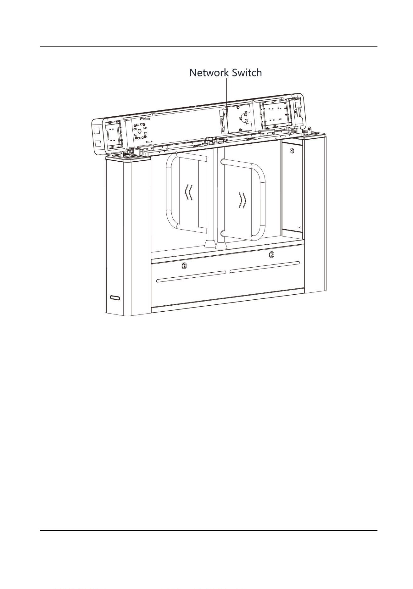
Figure 4-6 Network Switch Posion
2. Lead out 12 V power supply from the main switch and connect it to the network switch's power
interface.
3. Connect the network cable with the network switch.
4.5 Terminal
Descripon
The lane controller contains main lane controller and sub lane controller, which controls the IR
beams, motor, and other components' work.
4.5.1 Main Control Board Terminal
Descripon
The main lane control board contains interconnecng interfaces, BUS, motor encoder interface,
debugging port, door closed
posion interface, seven-segment display, strip light interface
(reserved), supercapacitor, power interface, motor drive interface, and DIP switch.
The picture displayed below is the main control board diagram.
DS-K3B601SX Series Swing Barrier Quick Start Guide
15
Loading ...
Loading ...
Loading ...