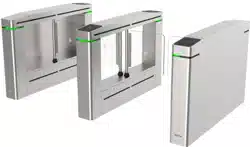

DS-K3B601SX Series Swing Barrier
Quick Start Guide

Legal Informaon
©2021 Hangzhou Hikvision Digital Technology Co., Ltd. All rights reserved.
About this Manual
The Manual includes instrucons for using and managing the Product. Pictures, charts, images and
all other informaon hereinaer are for descripon and explanaon only. The informaon
contained in the Manual is subject to change, without noce, due to rmware updates or other
reasons. Please
nd the latest version of this Manual at the Hikvision website ( hps://
www.hikvision.com/ ).
Please use this Manual with the guidance and assistance of professionals trained in
supporng the
Product.
Trademarks
and other Hikvision's trademarks and logos are the properes of
Hikvision in various
jurisdicons.
Other trademarks and logos menoned are the properes of their respecve owners.
Disclaimer
TO THE MAXIMUM EXTENT PERMITTED BY APPLICABLE LAW, THIS MANUAL AND THE PRODUCT
DESCRIBED, WITH ITS HARDWARE, SOFTWARE AND FIRMWARE, ARE PROVIDED "AS IS" AND "WITH
ALL FAULTS AND ERRORS". HIKVISION MAKES NO WARRANTIES, EXPRESS OR IMPLIED, INCLUDING
WITHOUT LIMITATION, MERCHANTABILITY, SATISFACTORY QUALITY, OR FITNESS FOR A PARTICULAR
PURPOSE. THE USE OF THE PRODUCT BY YOU IS AT YOUR OWN RISK. IN NO EVENT WILL HIKVISION
BE LIABLE TO YOU FOR ANY SPECIAL, CONSEQUENTIAL, INCIDENTAL, OR INDIRECT DAMAGES,
INCLUDING, AMONG OTHERS, DAMAGES FOR LOSS OF BUSINESS PROFITS, BUSINESS
INTERRUPTION, OR LOSS OF DATA, CORRUPTION OF SYSTEMS, OR LOSS OF DOCUMENTATION,
WHETHER BASED ON BREACH OF CONTRACT, TORT (INCLUDING NEGLIGENCE), PRODUCT LIABILITY,
OR OTHERWISE, IN CONNECTION WITH THE USE OF THE PRODUCT, EVEN IF HIKVISION HAS BEEN
ADVISED OF THE POSSIBILITY OF SUCH DAMAGES OR LOSS.
YOU ACKNOWLEDGE THAT THE NATURE OF THE INTERNET PROVIDES FOR INHERENT SECURITY
RISKS, AND HIKVISION SHALL NOT TAKE ANY RESPONSIBILITIES FOR ABNORMAL OPERATION,
PRIVACY LEAKAGE OR OTHER DAMAGES RESULTING FROM CYBER-ATTACK, HACKER ATTACK, VIRUS
INFECTION, OR OTHER INTERNET SECURITY RISKS; HOWEVER, HIKVISION WILL PROVIDE TIMELY
TECHNICAL SUPPORT IF REQUIRED.
YOU AGREE TO USE THIS PRODUCT IN COMPLIANCE WITH ALL APPLICABLE LAWS, AND YOU ARE
SOLELY RESPONSIBLE FOR ENSURING THAT YOUR USE CONFORMS TO THE APPLICABLE LAW.
ESPECIALLY, YOU ARE RESPONSIBLE, FOR USING THIS PRODUCT IN A MANNER THAT DOES NOT
INFRINGE ON THE RIGHTS OF THIRD PARTIES, INCLUDING WITHOUT LIMITATION, RIGHTS OF
PUBLICITY, INTELLECTUAL PROPERTY RIGHTS, OR DATA PROTECTION AND OTHER PRIVACY RIGHTS.
YOU SHALL NOT USE THIS PRODUCT FOR ANY PROHIBITED END-USES, INCLUDING THE
DEVELOPMENT OR PRODUCTION OF WEAPONS OF MASS DESTRUCTION, THE DEVELOPMENT OR
DS-K3B601SX Series Swing Barrier Quick Start Guide
i

PRODUCTION OF CHEMICAL OR BIOLOGICAL WEAPONS, ANY ACTIVITIES IN THE CONTEXT RELATED
TO ANY NUCLEAR EXPLOSIVE OR UNSAFE NUCLEAR FUEL-CYCLE, OR IN SUPPORT OF HUMAN
RIGHTS ABUSES.
IN THE EVENT OF ANY CONFLICTS BETWEEN THIS MANUAL AND THE APPLICABLE LAW, THE LATER
PREVAILS.
Data Protecon
During the use of device, personal data will be collected, stored and processed. To protect data,
the development of Hikvision devices incorporates privacy by design principles. For example, for
device with facial recognion features, biometrics data is stored in your device with encrypon
method; for ngerprint device, only ngerprint template will be saved, which is impossible to
reconstruct a ngerprint image.
As data controller, you are advised to collect, store, process and transfer data in accordance with
the applicable data
protecon laws and regulaons, including without limitaon, conducng
security controls to safeguard personal data, such as, implemenng reasonable administrave and
physical security controls, conduct periodic reviews and assessments of the
eecveness of your
security controls.
DS-K3B601SX Series Swing Barrier Quick Start Guide
ii
Regulatory Informaon
FCC Informaon
Please take aenon that changes or modicaon not expressly approved by the party responsible
for compliance could void the user’s authority to operate the equipment.
FCC compliance: This equipment has been tested and found to comply with the limits for a Class B
digital device, pursuant to part 15 of the FCC Rules. These limits are designed to provide
reasonable
protecon against harmful interference in a residenal installaon. This equipment
generates, uses and can radiate radio frequency energy and, if not installed and used in accordance
with the
instrucons, may cause harmful interference to radio communicaons. However, there is
no guarantee that interference will not occur in a parcular installaon. If this equipment does
cause harmful interference to radio or television
recepon, which can be determined by turning
the equipment o and on, the user is encouraged to try to correct the interference by one or more
of the following measures:
—Reorient or relocate the receiving antenna.
—Increase the
separaon between the equipment and receiver.
—Connect the equipment into an outlet on a circuit dierent from that to which the receiver is
connected.
—Consult the dealer or an experienced radio/TV technician for help
This equipment should be installed and operated with a minimum distance 20cm between the
radiator and your body.
FCC
Condions
This device complies with part 15 of the FCC Rules. Operaon is subject to the following two
condions:
1. This device may not cause harmful interference.
2. This device must accept any interference received, including interference that may cause
undesired
operaon.
EU Conformity Statement
This product and - if applicable - the supplied accessories too are marked with "CE"
and comply therefore with the applicable harmonized European standards listed
DS-K3B601SX Series Swing Barrier Quick Start Guide
iii
under the EMC Direcve 2014/30/EU, RE Direcve 2014/53/EU,the RoHS Direcve
2011/65/EU
2012/19/EU (WEEE direcve): Products marked with this symbol cannot be disposed
of as unsorted municipal waste in the European Union. For proper recycling, return
this product to your local supplier upon the purchase of equivalent new equipment,
or dispose of it at designated
collecon points. For more informaon see:
www.recyclethis.info
2006/66/EC (baery direcve): This product contains a baery that cannot be
disposed of as unsorted municipal waste in the European Union. See the product
documentaon for specic baery informaon. The baery is marked with this
symbol, which may include
leering to indicate cadmium (Cd), lead (Pb), or mercury
(Hg). For proper recycling, return the
baery to your supplier or to a designated
collecon point. For more informaon see:www.recyclethis.info
DS-K3B601SX Series Swing Barrier Quick Start Guide
iv
Safety Instrucon
These instrucons are intended to ensure that user can use the product correctly to avoid danger
or property loss.
The
precauon measure is divided into Dangers and Cauons:
Dangers: Neglecng any of the warnings may cause serious injury or death.
Cauons: Neglecng any of the cauons may cause injury or equipment damage.
Dangers: Follow these safeguards to prevent
serious injury or death.
Cauons: Follow these precauons to prevent
potenal injury or material damage.
Danger:
• In the use of the product, you must be in strict compliance with the electrical safety regulaons
of the naon and region.
• The equipment must be connected to an earthed mains socket-outlet.
• Shock hazard! Disconnect all power sources before maintenance.
• Do not touch the bare metal contacts of the inlets
aer the circuit breaker is turned o.
Electricity sll exists.
•
indicates hazardous live and the external wiring connected to the terminals requires
installaon by an instructed person.
• Keep body parts away from fan blades. Disconnect the power source during servicing.
• Keep body parts away from motors. Disconnect the power source during servicing.
• To prevent possible hearing damage, do not listen at high volume levels for long periods.
• All the electronic
operaon should be strictly compliance with the electrical safety regulaons,
re
prevenon regulaons and other related regulaons in your local region.
• Do not connect several devices to one power adapter as adapter overload may cause over-heat
or re hazard.
• Please make sure that the power has been disconnected before you wire, install or dismantle the
device.
If the top caps should be open and the device should be powered on for maintenance, make
sure:
1. Power
o the fan to prevent the operator from geng injured accidentally.
2. Do not touch bare high-voltage components.
3. Make sure the switch’s wiring sequence is correct
aer maintenance.
• Please make sure that the power has been disconnected before you wire, install or dismantle the
device.
• When the product is installed on wall or ceiling, the device shall be
rmly xed.
• If smoke, odors or noise rise from the device, turn o the power at once and unplug the power
cable, and then please contact the service center.
DS-K3B601SX Series Swing Barrier Quick Start Guide
v

• Do not ingest
baery, Chemical Burn Hazard.
This product contains a coin/buon cell baery. If the coin/buon cell baery is swallowed, it
can cause severe internal burns in just 2 hours and can lead to death.
Keep new and used baeries away from children. If the baery compartment does not close
securely, stop using the product and keep it away from children. If you think baeries might have
been swallowed or placed inside any part of the body, seek immediate medical aenon.
• If the product does not work properly, please contact your dealer or the nearest service center.
Never aempt to disassemble the device yourself. (We shall not assume any responsibility for
problems caused by unauthorized repair or maintenance.)
Cauons:
• The equipment shall not be exposed to dripping or splashing and that no objects lled with
liquids, such as vases, shall be placed on the equipment.
• Ensure correct wiring of the terminals for
connecon to an AC mains supply.
• The equipment has been designed, when required, modied for connecon to an IT power
distribuon system.
• + idenes the posive terminal(s) of equipment which is used with, or generates direct current.
+
idenes the negave terminal(s) of equipment which is used with, or generates direct
current.
• No naked ame sources, such as lighted candles, should be placed on the equipment.
• This equipment is suitable for
mounng on concrete or other non-combusble surface only.
• Install the equipment according to the instrucons in this manual.
• To prevent injury, this equipment must be securely
aached to the oor/wall in accordance with
the installaon instrucons.
• Stainless steel may be corroded in some circumstances. You need to clean and care the device by
using the stainless steel cleaner. It is suggested to clean the device every month.
• Do not drop the device or subject it to physical shock, and do not expose it to high
electromagnesm radiaon. Avoid the equipment installaon on vibraons surface or places
subject to shock (ignorance can cause equipment damage).
• Do not place the device in extremely hot (refer to the
specicaon of the device for the detailed
operang temperature), cold, dusty or damp locaons, and do not expose it to high
electromagnec radiaon.
• The device cover for indoor use shall be kept from rain and moisture.
• Exposing the equipment to direct sun light, low
venlaon or heat source such as heater or
radiator is forbidden (ignorance can cause re danger).
• Do not aim the device at the sun or extra bright places. A blooming or smear may occur
otherwise (which is not a
malfuncon however), and aecng the endurance of sensor at the
same me.
• Please use the provided glove when open up the device cover, avoid direct contact with the
device cover, because the acidic sweat of the ngers may erode the surface coang of the device
cover.
• Please use a
so and dry cloth when clean inside and outside surfaces of the device cover, do
not use alkaline detergents.
DS-K3B601SX Series Swing Barrier Quick Start Guide
vi

• Please keep all wrappers
aer unpack them for future use. In case of any failure occurred, you
need to return the device to the factory with the original wrapper. Transportaon without the
original wrapper may result in damage on the device and lead to addional costs.
• Improper use or replacement of the baery may result in hazard of explosion. Replace with the
same or equivalent type only. Dispose of used
baeries according to the instrucons provided by
the baery manufacturer.
• Biometric
recognion products are not 100% applicable to an-spoong environments. If you
require a higher security level, use mulple authencaon modes.
• Do not stay in the lane when the device is
reboong.
• RISK OF EXPLOSION IF BATTERY IS REPLACED BY AN INCORRECT TYPE. DISPOSE OF USED
BATTERIES ACCORDING TO THE INSTRUCTIONS.
• SUITABLE FOR MOUNTING ON CONCRETE OR OTHER NON-COMBUSTIBLE SURFACE ONLY.
• The
instrucons shall require connecon of the equipment protecve earthing conductor to the
installaon protecve earthing conductor.
DS-K3B601SX Series Swing Barrier Quick Start Guide
vii
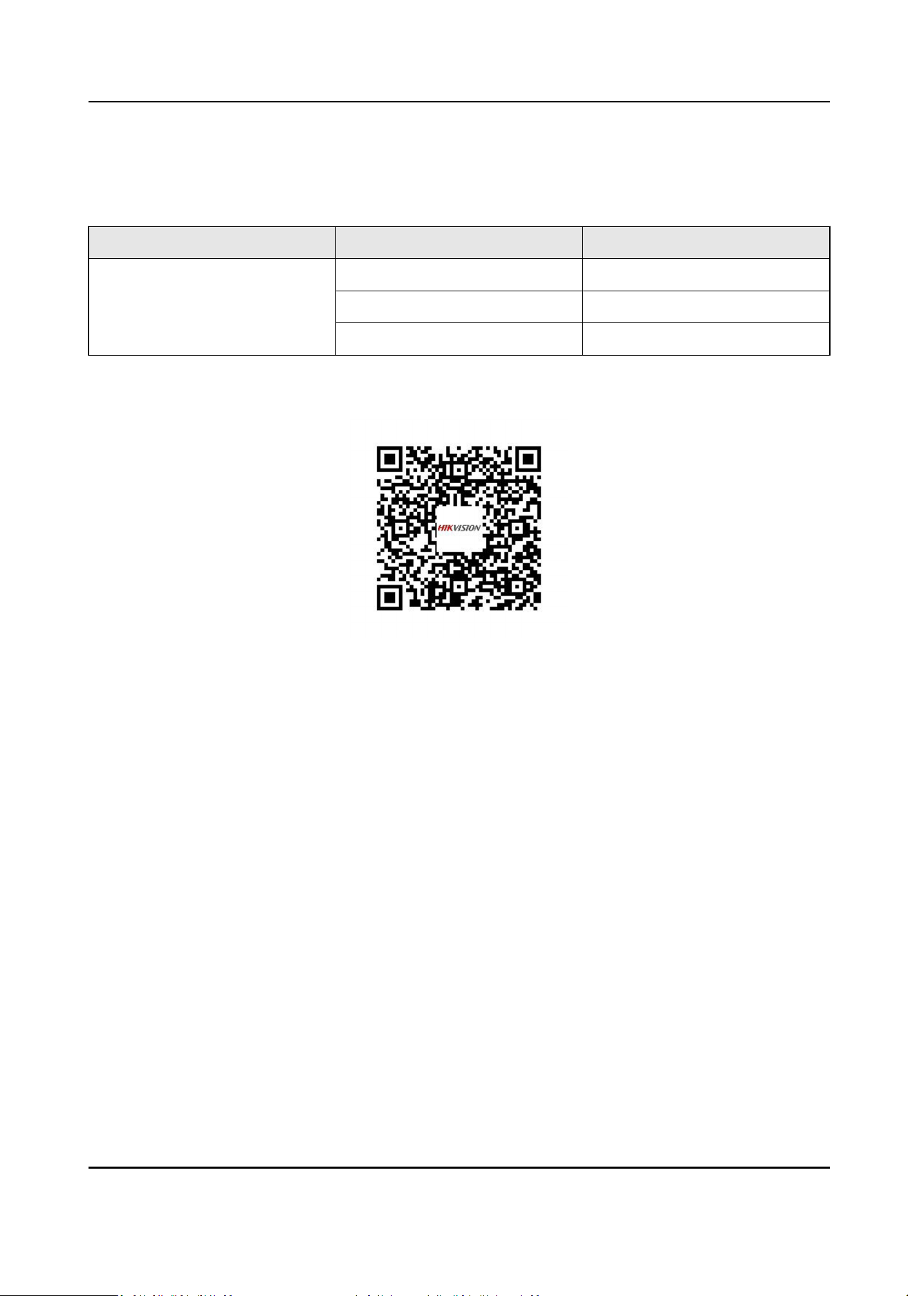
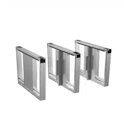
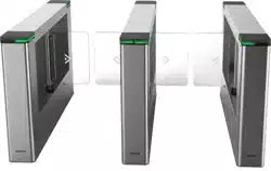
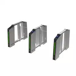
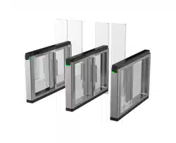
Available Models
Product Name Model Descripon
Swing Barrier DS-K3B601SX-L Le Pedestal
DS-K3B601SX-M Middle Pedestal
DS-K3B601SX-R Right Pedestal
Scan the QR code to get User Manual of Swing Barrier. Note that mobile data charges may apply if
Wi-Fi is unavailable.
DS-K3B601SX Series Swing Barrier Quick Start Guide
viii

Contents
Chapter 1 Overview .................................................................................................................... 1
1.1 Introducon ........................................................................................................................... 1
1.2 Main Features ........................................................................................................................ 1
Chapter 2 System Wiring ............................................................................................................ 2
Chapter 3 Installaon ................................................................................................................. 8
3.1 Disassemble Pedestals ........................................................................................................... 8
3.2 Install Pedestals ..................................................................................................................... 8
Chapter 4 General Wiring ......................................................................................................... 10
4.1 Components
Introducon .................................................................................................... 10
4.2 Wiring Electric Supply .......................................................................................................... 11
4.3 Wire Interconnecng Cable ................................................................................................. 12
4.4 Wire Network Switch ........................................................................................................... 13
4.5 Terminal
Descripon ............................................................................................................ 15
4.5.1 Main Control Board Terminal Descripon ................................................................... 15
4.5.2 Sub Control Board Terminal
Descripon ..................................................................... 16
4.5.3 Access Control Board Terminal Descripon ................................................................ 17
4.5.4 Access Control Board Serial Port ID Descripon ......................................................... 20
4.5.5 RS-485 Wiring ............................................................................................................. 23
4.5.6 RS-232 Wiring ............................................................................................................. 23
4.5.7 Wiegand Wiring .......................................................................................................... 25
4.5.8 Barrier Control Wiring ................................................................................................. 25
4.5.9 Alarm Output Wiring ................................................................................................... 27
Chapter 5 Device
Sengs ......................................................................................................... 28
5.1 Set Study Mode .................................................................................................................... 28
5.2 Pair Keyfob
(Oponal) .......................................................................................................... 29
5.3 Inialize Device .................................................................................................................... 30
DS-K3B601SX Series Swing Barrier Quick Start Guide
ix

5.4 Switch to RS-485/RS-232 Mode ........................................................................................... 31
5.5 Switch Relay Output Mode (NO/NC) .................................................................................... 31
5.5.1 Barrier Control Relay Output Mode ............................................................................ 31
5.5.2 Alarm Relay Output Mode (NO/NC) ............................................................................ 32
Chapter 6
Acvaon ................................................................................................................. 33
6.1 Acvate via SADP ................................................................................................................. 33
6.2 Acvate Device via Client Soware ...................................................................................... 34
Appendix A. Tips for Scanning Fingerprint ................................................................................ 36
Appendix B. DIP Switch ............................................................................................................ 38
B.1 DIP Switch Descripon ......................................................................................................... 38
B.2 DIP Switch Corresponded Funcons .................................................................................... 38
Appendix C. Event and Alarm Type ........................................................................................... 41
Appendix D. Table of Audio Index Related Content ................................................................... 42
Appendix E. Error Code Descripon .......................................................................................... 43
Appendix F. Communicaon Matrix and Device Command ....................................................... 44
DS-K3B601SX Series Swing Barrier Quick Start Guide
x

Chapter 1 Overview
1.1 Introducon
The swing barrier with two barriers and 20 IR lights is designed to detect unauthorized entrance or
exit. By adopng the swing barrier integratedly with the access control system, person should
authencate to pass through the lane via swiping IC or ID card, scanning QR code, etc. It is widely
used in aracons, stadiums, construcon sites, residences, etc.
1.2 Main Features
• 32-bit high-speed processor
• TCP/IP network communicaon
The communicaon data is specially encrypted to relieve the concern of privacy leak
• Permissions validaon and an-tailgang
• Remaining open/closed mode selectable
• Bidireconal (Entering/Exing) lane
The barrier opening and closing speed can be congured according to the visitor ow
• The barrier will stop working when people are nipped
• An-forced-accessing
The barrier will be locked automacally without open-barrier signal.
• Self-detecon, Self-diagnoscs, and automac alarm
• Audible and visual alarm will be triggered when
detecng intrusion, tailgang, reverse passing,
and climbing over barrier
• Remote control and management
•
Online/oine operaon
• LED indicates the entrance/exit and passing status
• Barrier is in free status when powered down; If the device is installed with lithium
baery
(oponal), the barrier remains open when powered down
• Fire alarm passing
When the
re alarm is triggered, the barrier will be open automacally for emergency
evacuaon
• Valid passing duraon sengs
System will cancel the passing permission if a person does not pass through the lane within the
valid passing duraon
• Opens/Closes barrier according to the schedule template
• Up to 3000 visitor cards and up to 60,000 cards except for visitor cards can be added
DS-K3B601SX Series Swing Barrier Quick Start Guide
1
Chapter 2 System Wiring
The preparaon before installaon and general wiring.
Steps
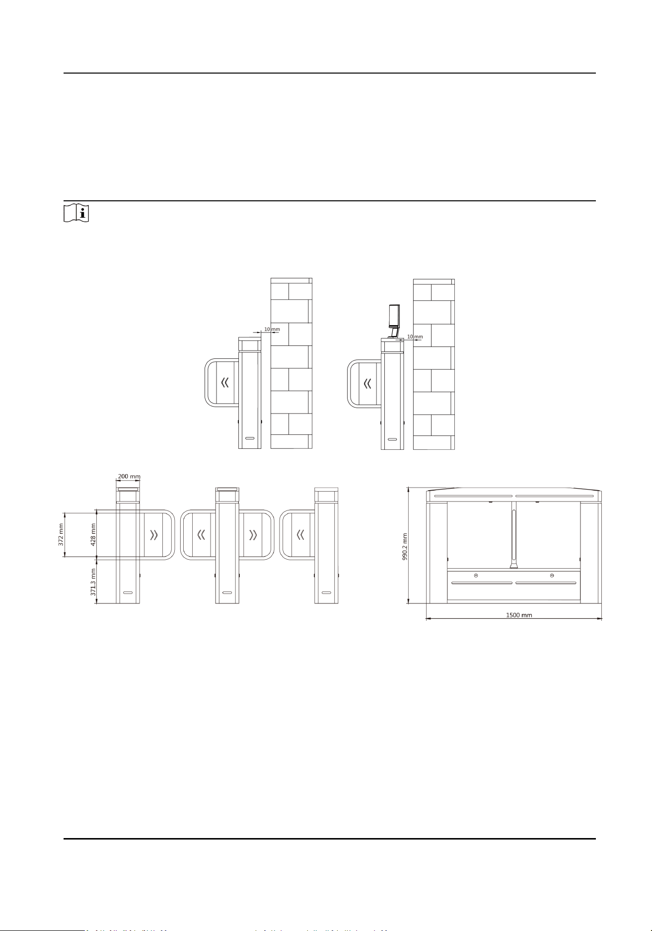
Note
• The device should be installed on the concrete surface or other
non-ammable surfaces.
• If the installaon area is too close to the wall, make sure the distance between the pedestal and
the wall should be no more than 10 mm, or you cannot open the pedestal's top panel.
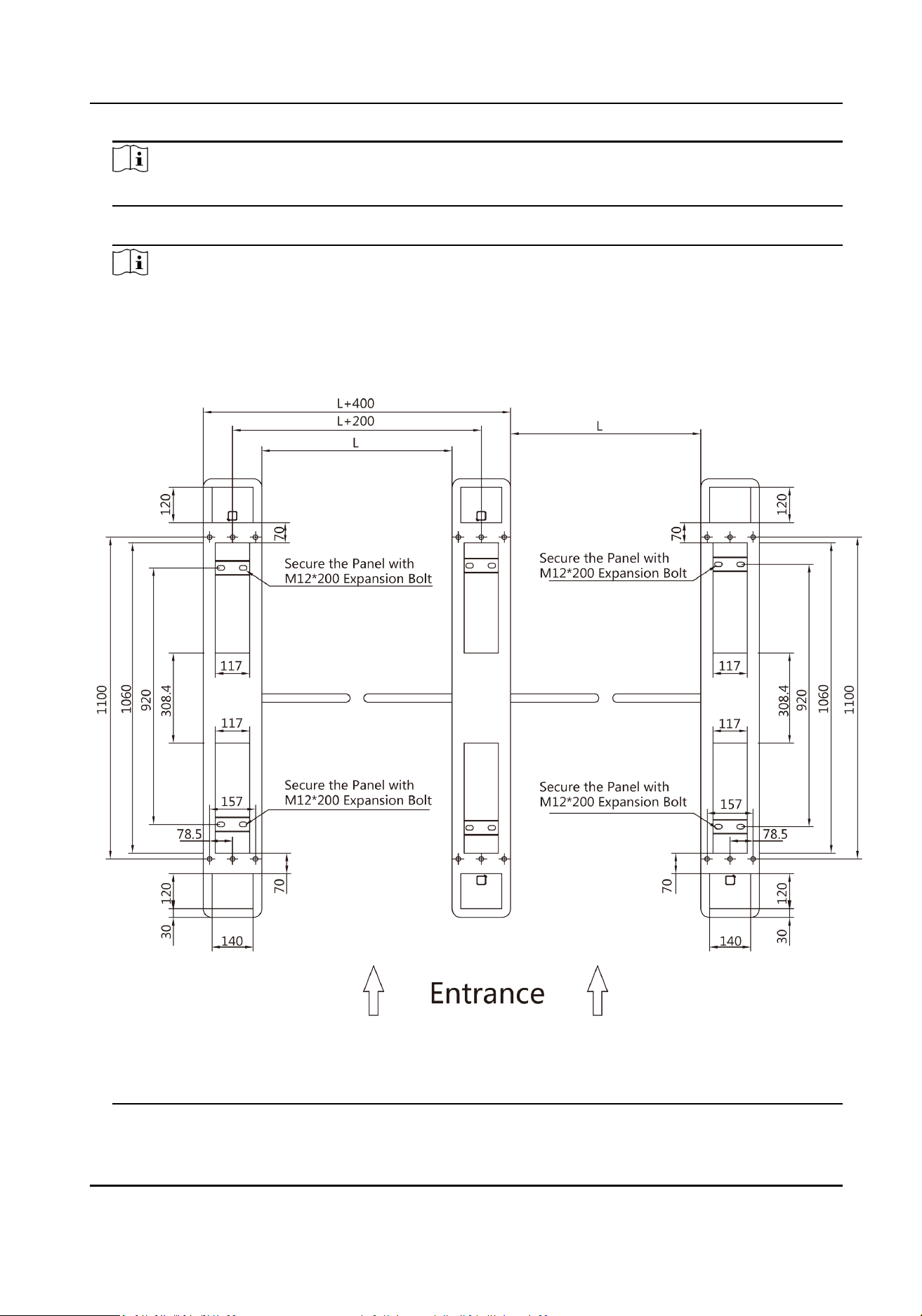
• The dimension is as follows.
Figure 2-1 Dimension (1500 mm)
DS-K3B601SX Series Swing Barrier Quick Start Guide
2
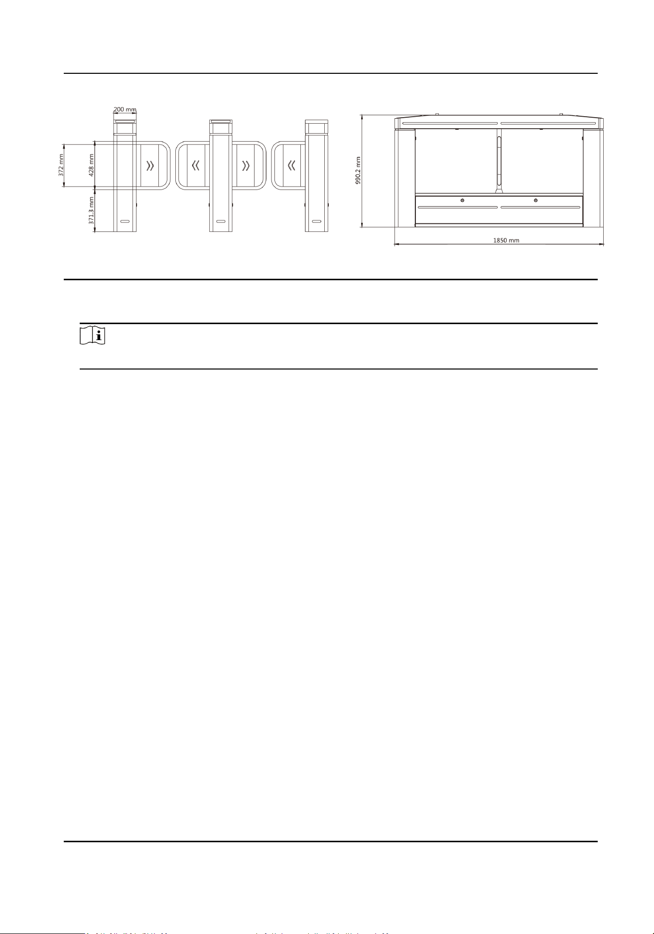
Figure 2-2 Dimension (1850 mm)
1. Draw a central line on the installaon surface of the le or right pedestal.
2. Draw other parallel lines for installing the other pedestals.
Note
The distance between the nearest two line is L+200 mm. L represents the lane width.
3. Slot on the installaon surface and dig installaon holes according to the hole posion diagram.
DS-K3B601SX Series Swing Barrier Quick Start Guide
3
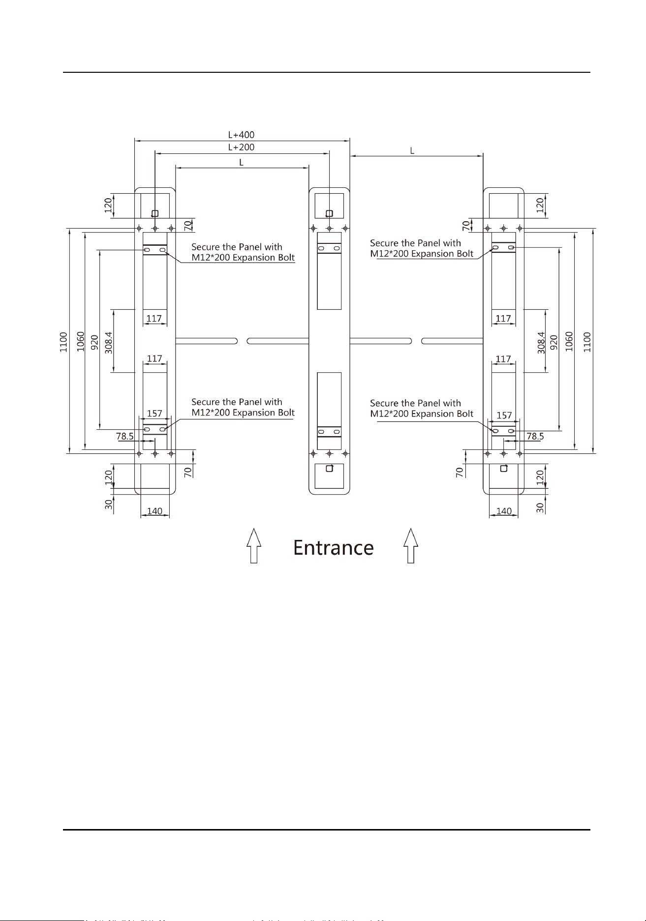
Figure 2-3 Hole Posion Diagram
4. Bury cables. Each lane buries 1 network cable and 1 high voltage cable. For details, see the
system wiring diagram below.
DS-K3B601SX Series Swing Barrier Quick Start Guide
4
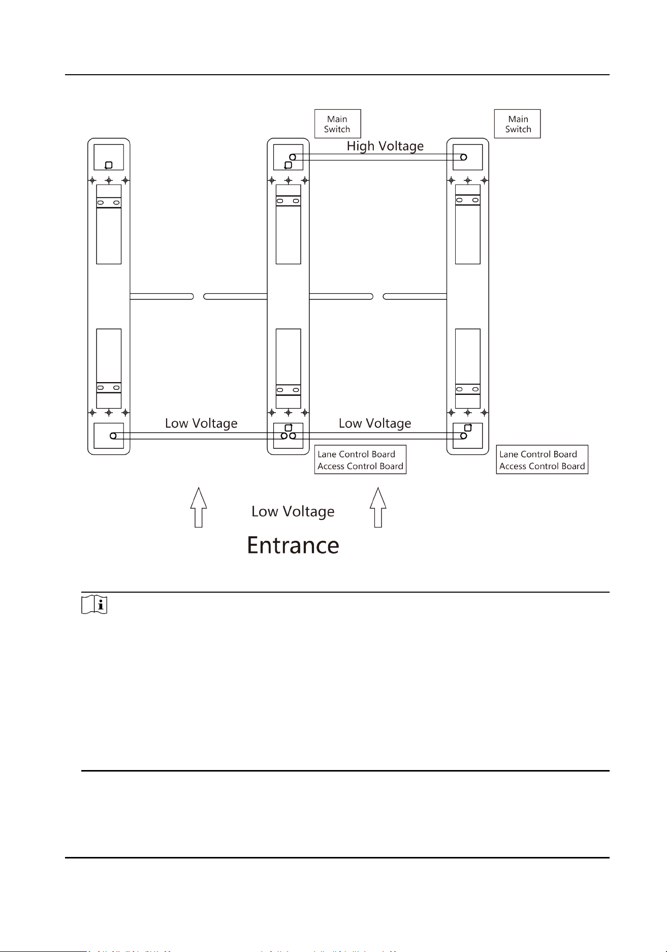
Figure 2-4 System Wiring Diagram (General Wiring)
Note
• The supplied
interconnecng cable length is 5.5 m.
• The suggested inner diameter of the low voltage conduit is larger than 30 mm.
• If you want to bury both of the AC power cord and the low voltage cable at the entrance, the
two cables should be in separated conduits to avoid interference.
• If more peripherals are required to connect, you should increase the conduit diameter or
bury another conduit for the external cables.
• The external AC power cord should be double-insulated.
• The network cable must be CAT5e or the network cable has
beer performance. And the
suggested network cable length should be less than 100 m.
DS-K3B601SX Series Swing Barrier Quick Start Guide
5
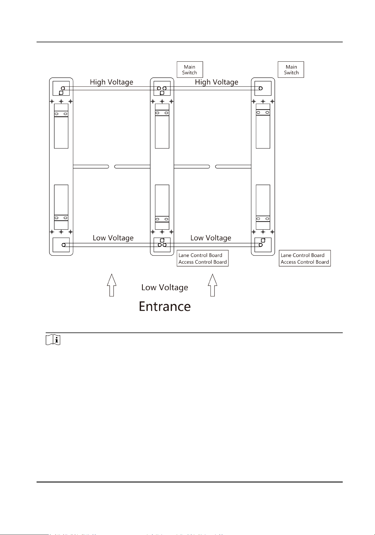
Figure 2-5 Wire Face Recognion Terminal
Note
• The supplied
interconnecng cable length is 5.5 m.
• The le pedestal and the middle pedestal should bury interconnecng cables for connecng
the face recognion terminal.
• The face
recognion terminal installed on the le pedestal will gain power from the 12 V
power supply, which should connect to the electric supply.
• The suggested inner diameter of the low voltage conduit is larger than 30 mm.
• If you want to bury both of the AC power cord and the low voltage cable at the entrance, the
two cables should be in separated conduits to avoid interference.
• If more peripherals are required to connect, you should increase the conduit diameter or
bury another conduit for the external cables.
DS-K3B601SX Series Swing Barrier Quick Start Guide
6

• The external AC power cord should be double-insulated.
• The network cable must be CAT5e or the network cable has
beer performance. And the
suggested network cable length should be less than 100 m.
DS-K3B601SX Series Swing Barrier Quick Start Guide
7
Chapter 3 Installaon
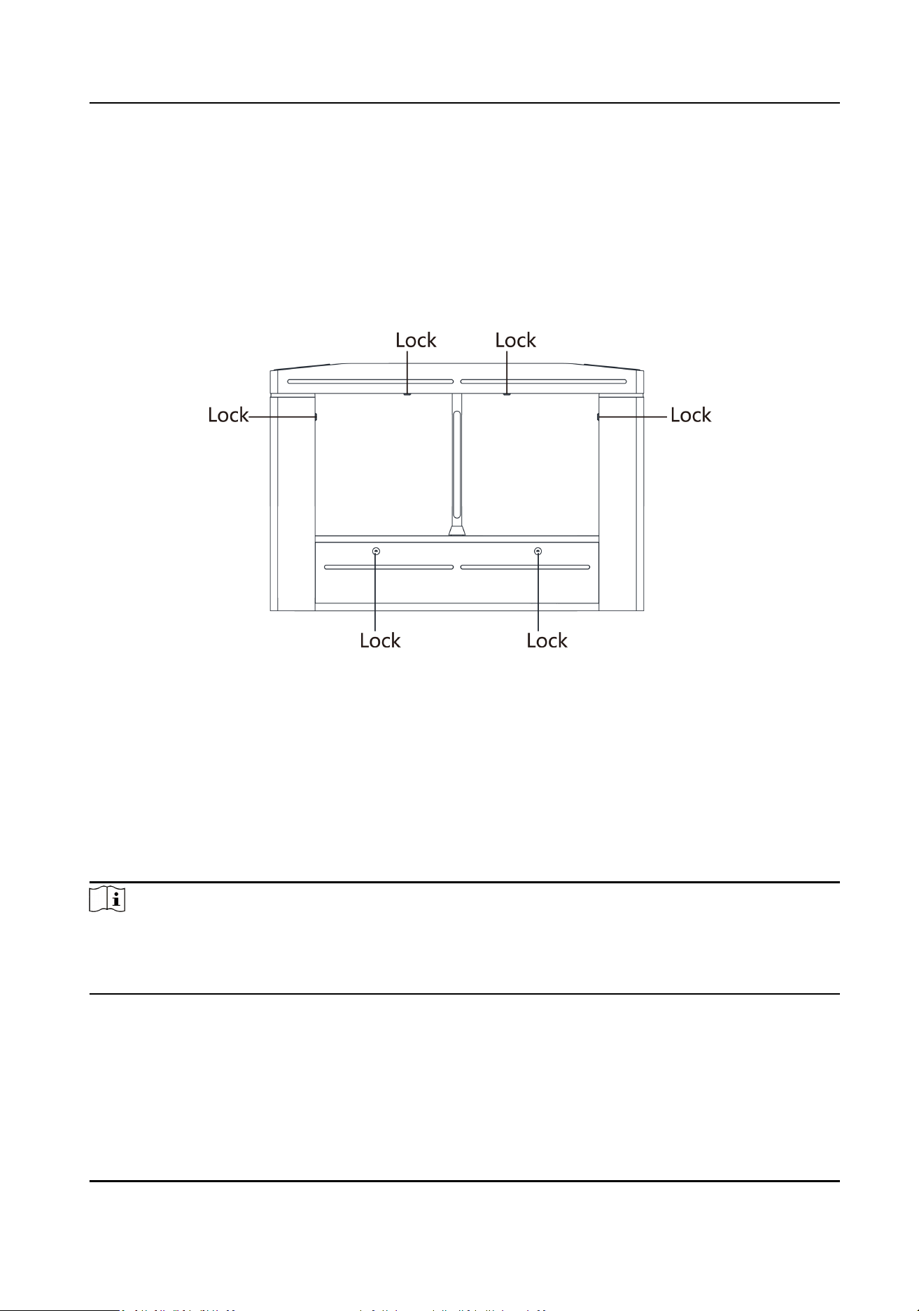
3.1 Disassemble Pedestals
Before installaon, you should use the key to open the pedestals.
View the pictures below to nd the lock holes.
Figure 3-1 Lock Holes
3.2 Install Pedestals
Before You Start
Prepare for the
installaon tools, check the device and the accessories, and clear the installaon
base.
Steps
Note
• The device should be installed on the concrete surface or other
non-ammable surfaces.
• If the installaon area is too close to the wall, make sure the distance between the pedestal and
the wall should be more than 10 mm, or you cannot open the pedestal's top panel.
1. Prepare for the installaon tools, check the components, and prepare for the installaon base.
2. Drill holes on the ground according to the
installaon holes on the pedestals and insert the
expansion sleeves.
3. According to the entrance and exit marks on the pedestals, move the pedestals to the
corresponded
posions.
DS-K3B601SX Series Swing Barrier Quick Start Guide
8
Note
Make sure the installaon holes on the pedestals and the base are aligned with each other.
4. Secure the pedestals with expansion bolts.
Note
• Do not immerse the pedestal in the water. In special circumstances, the immersed height
should be no more than 150 mm.
• The installaon footprint is as follows:
Figure 3-2 Installaon Footprint
DS-K3B601SX Series Swing Barrier Quick Start Guide
9
Chapter 4 General Wiring
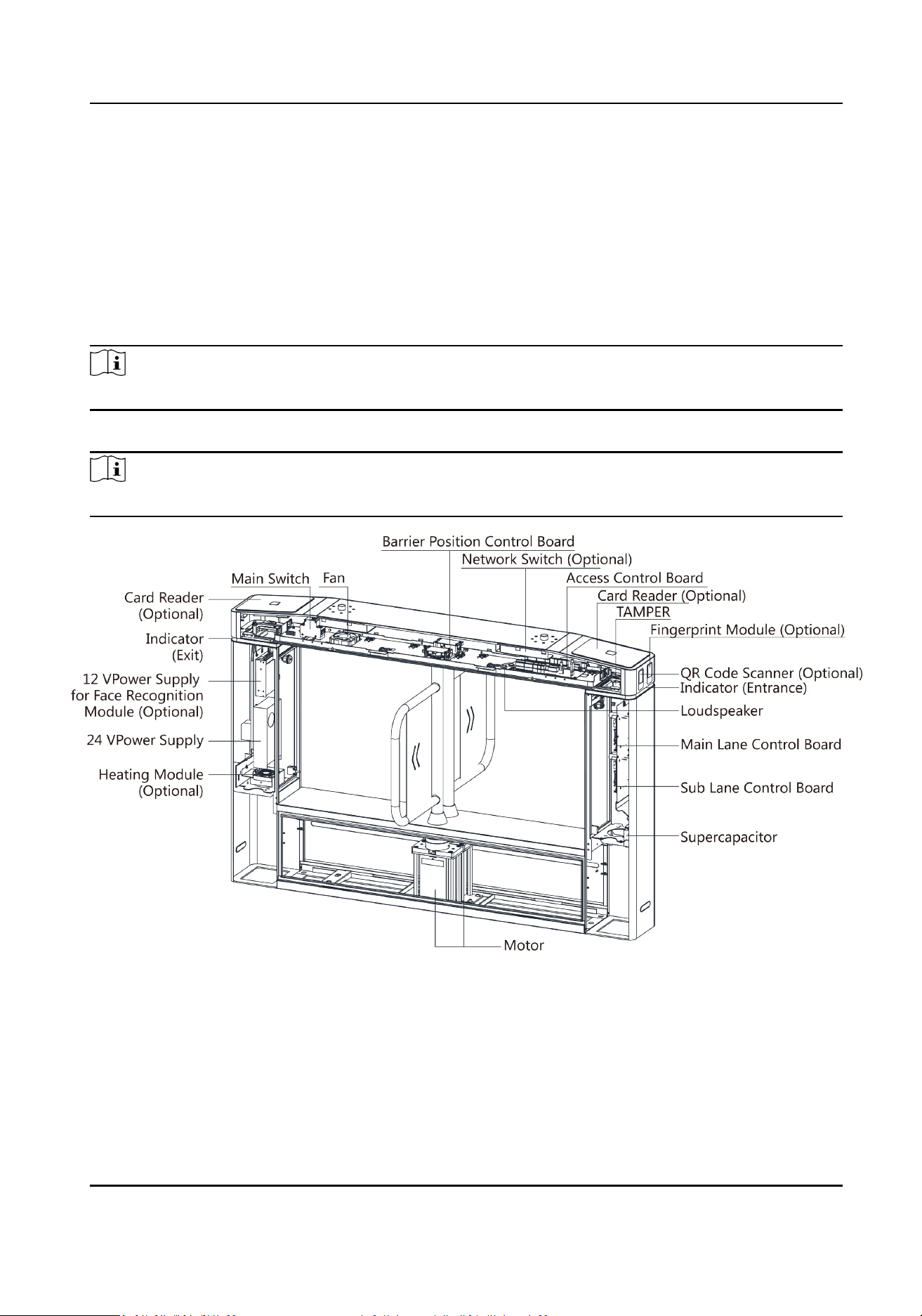
4.1 Components Introducon
By default, basic components of the turnsle are connected well. The pedestals can communicate
by wiring the interconnecng cables. And the turnsle supports wiring the AC electric supply for
the whole system’s power supply.
Note
The voltage uctuaon of the electric supply is between 100 VAC and 220 VAC, 50 to 60 Hz.
The picture displayed below describes each component's posion on the turnsle.
Note
The diagram is for reference only.
Figure 4-1 Components Diagram
The picture displayed below describes the IR sending/receiving module and their corresponding
number on the pedestal.
DS-K3B601SX Series Swing Barrier Quick Start Guide
10
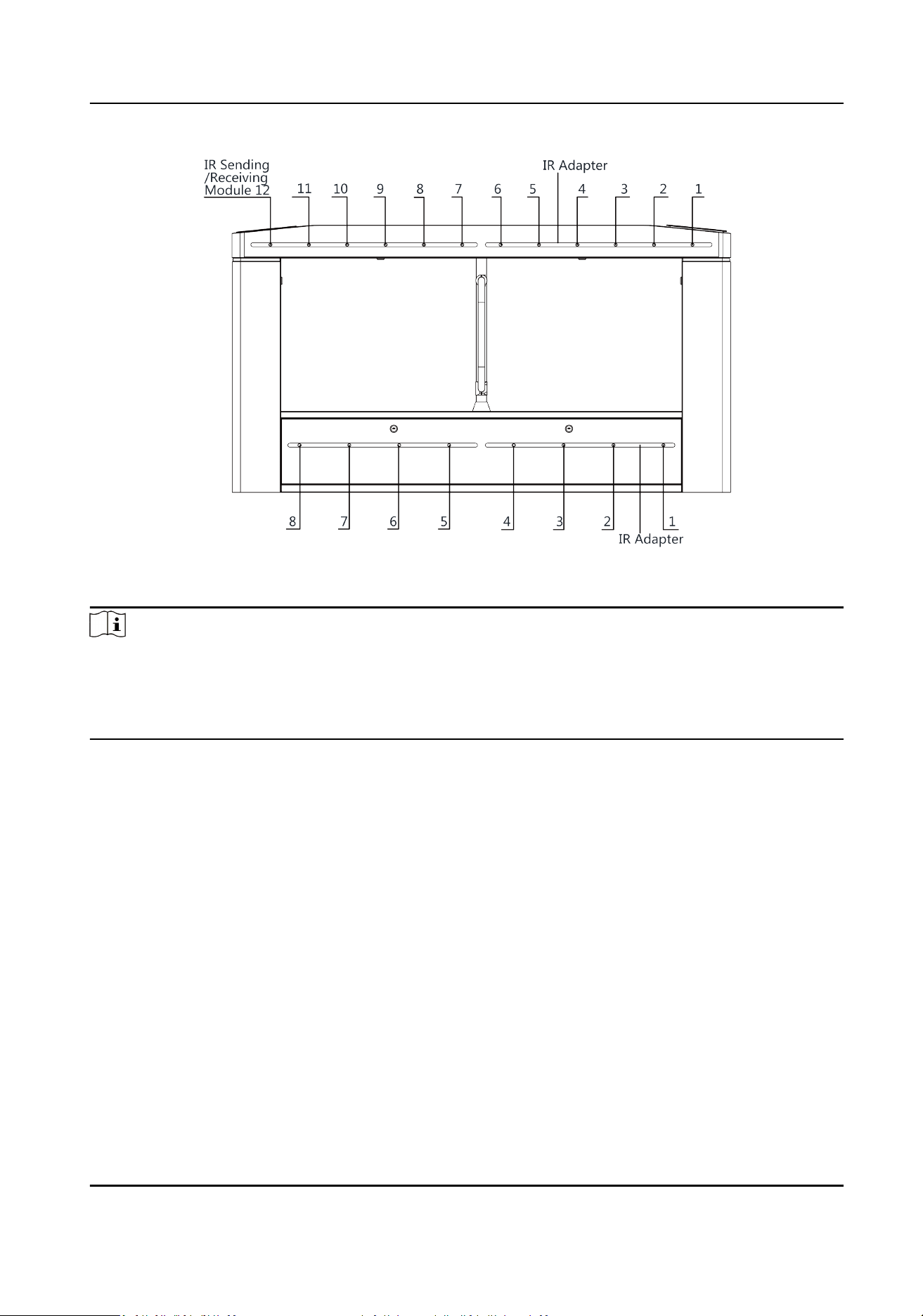
Figure 4-2 IR Sending/Receiving Module Posion
Note
If the turnsle contains two lanes, standing at the entrance posion, the IR modules on the le
pedestal are the IR sending modules. The IR modules on the right pedestal are the IR receiving
modules. The IR modules on the le side of the middle pedestal are the IR receiving modules,
while the IR modules on the right side of the middle pedestal are the IR sending modules.
4.2 Wiring Electric Supply
Wire electric supply with the switch in the pedestal. Terminal L and terminal N are on the switch,
while terminal PE should connect to a ground wire (yellow and green wire).
DS-K3B601SX Series Swing Barrier Quick Start Guide
11
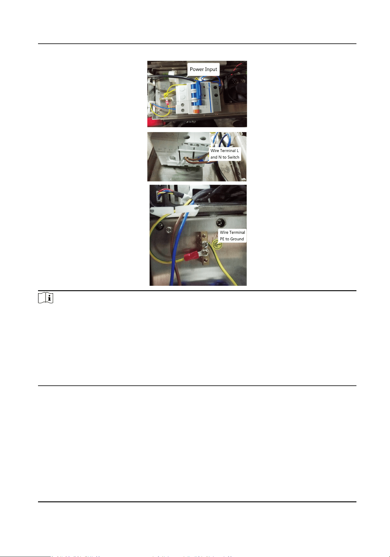
Note
• The cable bare part should be no more than 8 mm. It is suggested that you can immerse the
bare part into the liquid n. If possible, wear an insulaon cap at the end of the bare cable.
Make sure there’s no bare copper or cable aer the wiring.
• The Terminal L and the Terminal N cannot be wired reversely. Do not wire the input and output
terminal reversely.
• To avoid people injury and device damage, when
tesng, the ground resistance of the
equipotenal points should not be larger than 2 Ω。
• Use the device in
conjuncon with an UPS.
4.3 Wire Interconnecng Cable
You should use interconnecng cables to connect the main lane board and the sub lane board for
components communicaon.
The picture displayed below describes the cable hole's posion on the pedestals.
DS-K3B601SX Series Swing Barrier Quick Start Guide
12
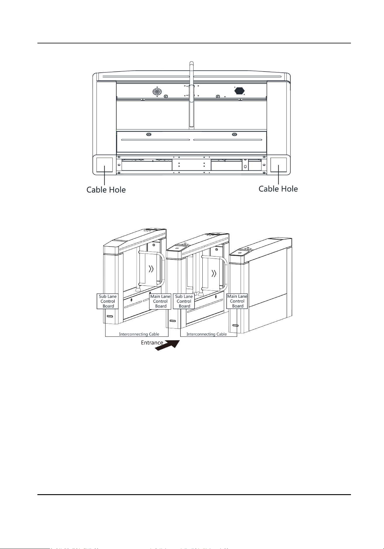
Figure 4-3 Cable Hole of Interconnecng Cable
Follow the instrucons below to connect the interconnecng cable.
Figure 4-4 Connect Interconnecng Cable
4.4 Wire Network Switch
Connect the network cable and the network switch.
Steps
1. Use the key to open the top cover of the pedestal.
DS-K3B601SX Series Swing Barrier Quick Start Guide
13
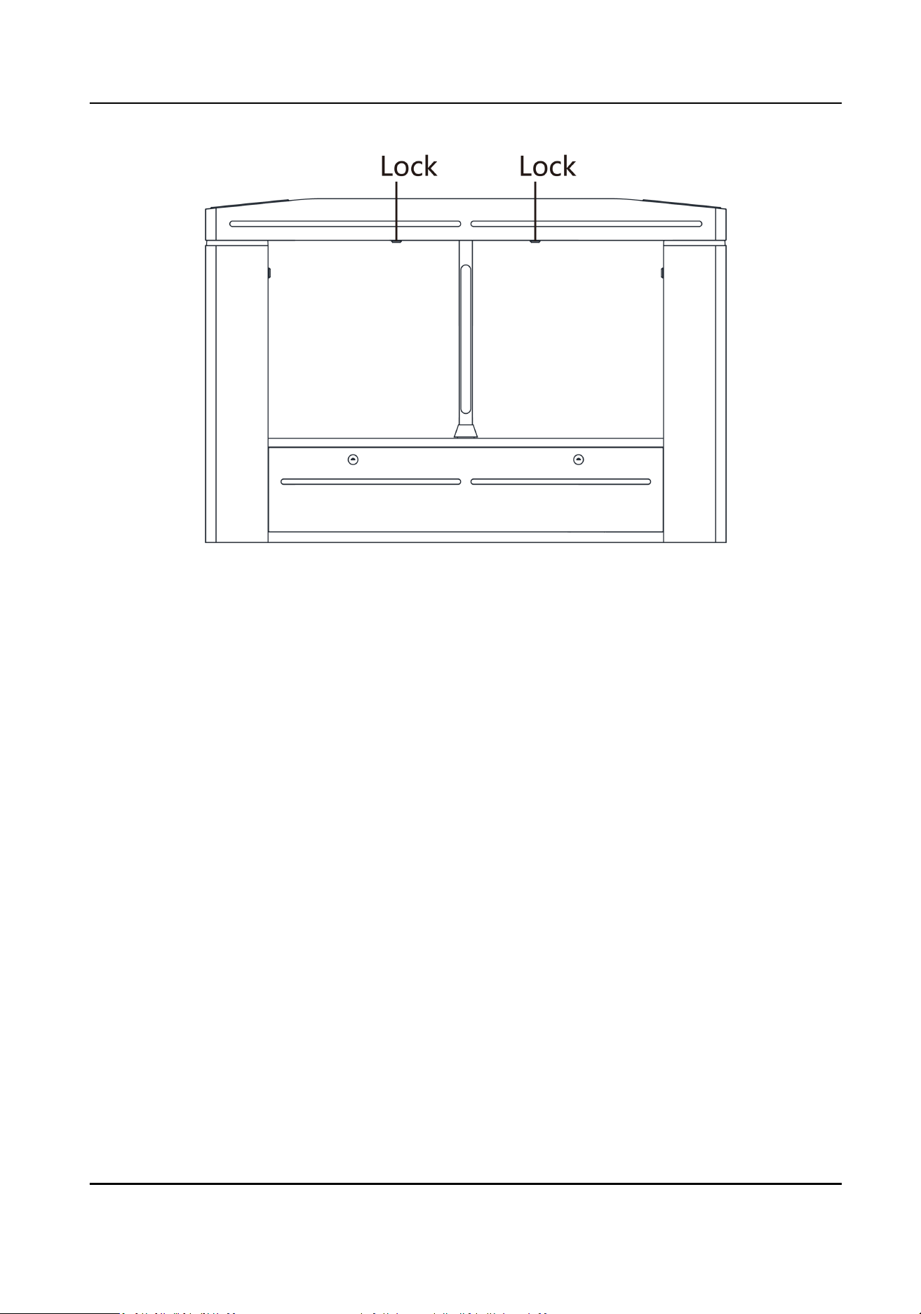
Figure 4-5 Open Top Cover
The network switch's posion is shown as follows.
DS-K3B601SX Series Swing Barrier Quick Start Guide
14
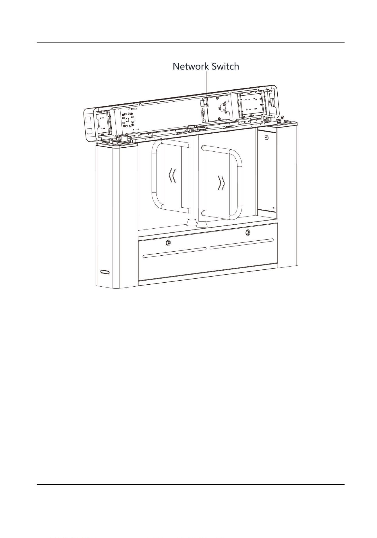
Figure 4-6 Network Switch Posion
2. Lead out 12 V power supply from the main switch and connect it to the network switch's power
interface.
3. Connect the network cable with the network switch.
4.5 Terminal
Descripon
The lane controller contains main lane controller and sub lane controller, which controls the IR
beams, motor, and other components' work.
4.5.1 Main Control Board Terminal
Descripon
The main lane control board contains interconnecng interfaces, BUS, motor encoder interface,
debugging port, door closed
posion interface, seven-segment display, strip light interface
(reserved), supercapacitor, power interface, motor drive interface, and DIP switch.
The picture displayed below is the main control board diagram.
DS-K3B601SX Series Swing Barrier Quick Start Guide
15
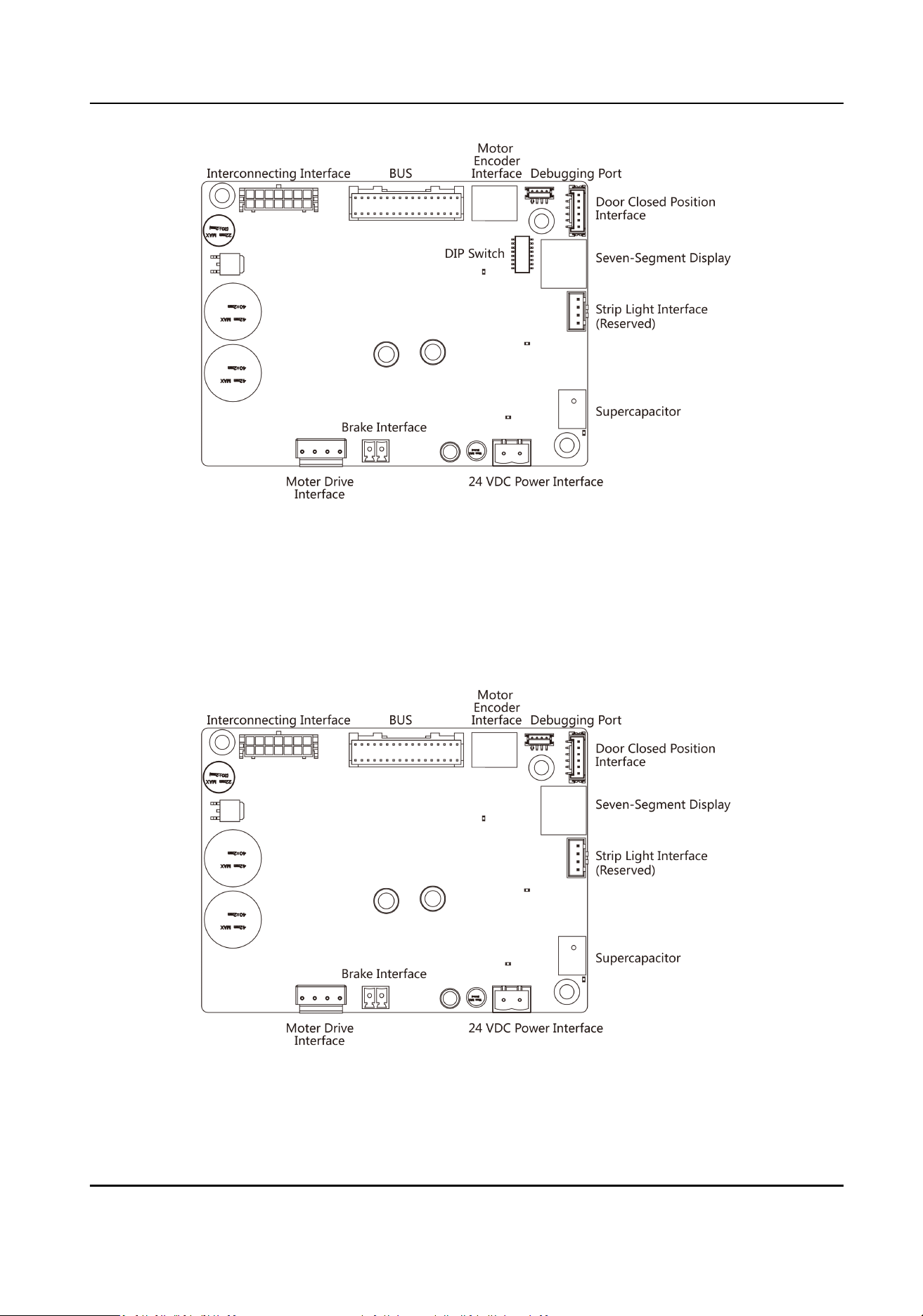
4.5.2 Sub Control Board Terminal Descripon
The sub lane control board contains interconnecng interfaces, BUS, motor encoder interface,
debugging port, door closed posion interface, seven-segment display, strip light interface
(reserved), supercapacitor, power interface, and motor drive interface.
The picture displayed below is the sub control board diagram.
DS-K3B601SX Series Swing Barrier Quick Start Guide
16
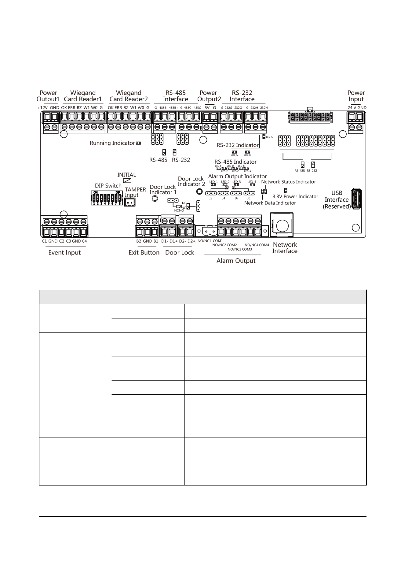
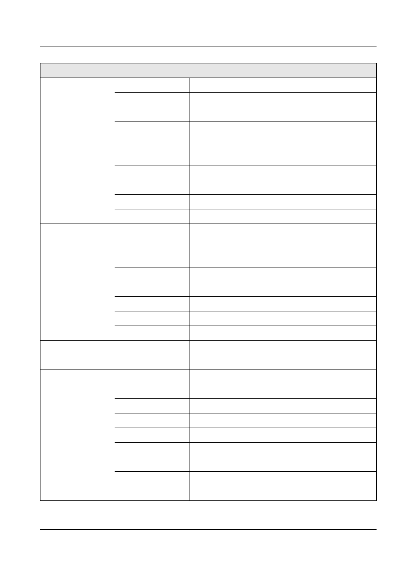
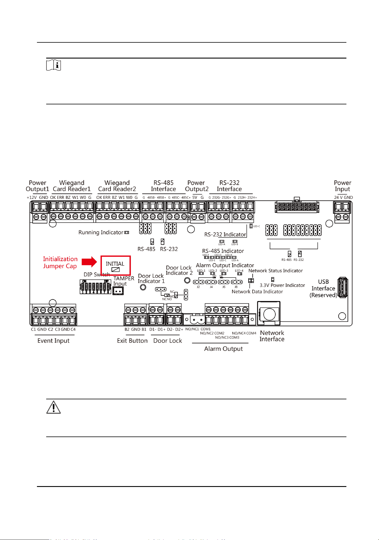
4.5.3 Access Control Board Terminal Descripon
Table 4-1 Access Control Board Terminal Descripon
Access Controlling Board Terminal Descripon
Power Output 1 +12 V Power Output
GND Grounding
Wiegand Card
Reader 1
OK Indicator of Card Reader Control Output (Invalid Card
Output)
ERR Indicator of Card Reader Control Output (Valid Card
Output)
BZ Card Reader Buzzer Control Output
W1 Wiegand Head Read Data Input Data1
W0 Wiegand Head Read Data Input Data0
GND Grounding
Wiegand Card
Reader 2
OK Indicator of Card Reader Control Output (Invalid Card
Output)
ERR Indicator of Card Reader Control Output (Valid Card
Output)
DS-K3B601SX Series Swing Barrier Quick Start Guide
17
Access Controlling Board Terminal Descripon
BZ Card Reader Buzzer Control Output
W1 Wiegand Head Read Data Input Data1
W0 Wiegand Head Read Data Input Data0
GND Grounding
RS-485 Interface GND Grounding
RS-485 B- Connect to Card Reader RS485-
RS-485 B+ Connect to Card Reader RS485+
GND Grounding
RS-485 C- Connect to Card Reader RS485-
RS-485 C+ Connect to Card Reader RS485+
Power Output 2 5 V 5 VDC Power Output
GND 5 VDC Grounding
RS-232 Interface GND Grounding
RS-232 G- Connect to Card Reader RS232-
RS-232 G+ Connect to Card Reader RS232+
GND Grounding
RS-232 H- Connect to Card Reader RS232-
RS-232 H+ Connect to Card Reader RS232+
Power Input +12 V 12 VDC Power Input
GND 12 VDC Grounding
Event Input C1 Event Alarm Input 1
GND Grounding
C2 Event Alarm Input 2
C3 Event Alarm Input 3
GND Grounding
C4 Event Alarm Input 4
Exit Buon B2 Door 2 Signal Input
GND Grounding
B1 Door 1 Signal Input
DS-K3B601SX Series Swing Barrier Quick Start Guide
18
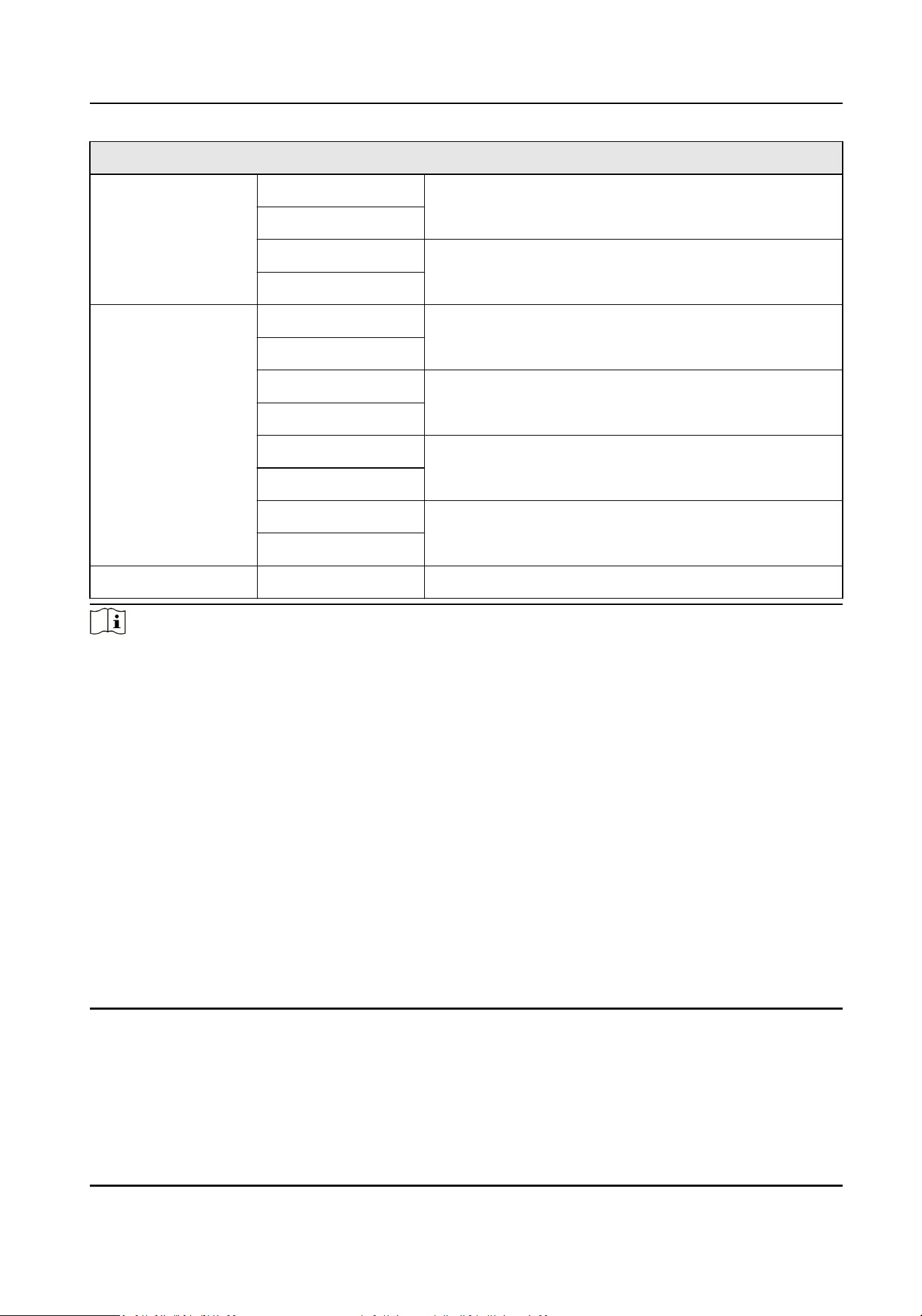
Access Controlling Board Terminal Descripon
Door Lock (Relay) D1- Door 1 Relay Output (Dry Contact)
D1+
D2- Door 2 Relay Output (Dry Contact)
D2+
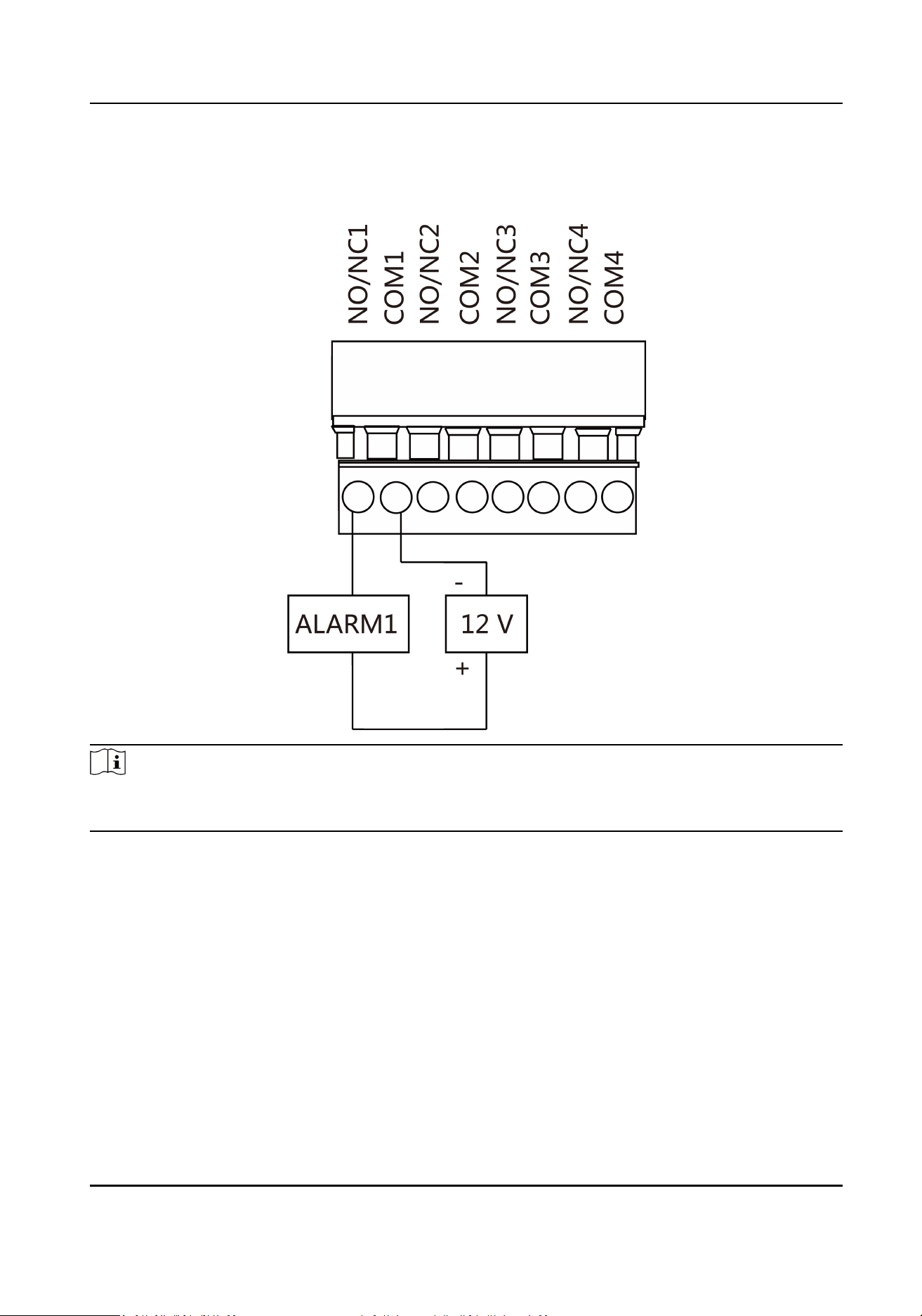
Alarm Output NO/NC1 Alarm Output Relay 1 (Dry Contact)
COM1
NO/NC2 Alarm Output Relay 2 (Dry Contact)
COM2
NO/NC3 Alarm Output Relay 3 (Dry Contact)
COM3
NO/NC4 Alarm Output Relay 4 (Dry Contact)
COM4
Network Interface LAN Network Accessing
Note
• The alarm input hardware interface is normally open by default. So only the normally open
signal is allowed. It can be linked to the buzzer of the card reader and access controller, and the
alarm relay output and open door relay output.
• The DIP of RS485 card ID is set as 1 and4 by default. 1 is for entering, and 4 is for exing. Set the
DIP as 3 for
connecng visitor card reader.
• The Wiegand card reader 1 and 2
respecvely refer to the entering and exing card reader.
• The alarm output supports relay output.
• For any requirements, the door lock can control the door barrier status of the third party. D1
controls the barrier opening for entrance, while D2 controls the door opening for exit. For
details, see Barrier Control Relay Output Mode .
• C3 and C4 in the event input can also be people counng interface. C3 controls people counng
for entrance, while C4 controls people counng for exit. When the access control board detects
signals in C3 and C4, the people number will be accumulated. For detailed informaon about
people counng and people number, see Conguring People Counng Parameters in User
Manual of iVMS-4200 AC Client
Soware.
• For detailed informaon about the DIP switch, see DIP Switch Descripon.
DS-K3B601SX Series Swing Barrier Quick Start Guide
19
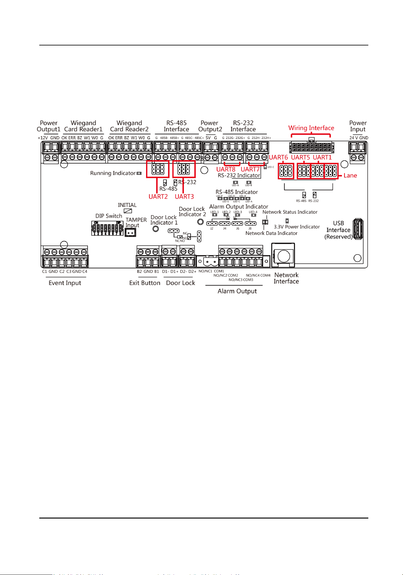
4.5.4 Access Control Board Serial Port ID Descripon
You can use the jumper cap on the access control board to switch the interface communicaon
mode. For details about switching between RS-232 and RS-485 communicaon type, see Switching
RS-485/RS-232 Mode.
Figure 4-7 Access Control Board
According to the picture above, the RS-485 serial port corresponds to UART2 and UART3. RS-232
serial port is corresponded to UART7 and UART8. Wiring Interface is corresponded to UART1,
UART4, UART6, UART6, and Lane.
The access control board
descripons are as follows:
UART2/UART3 Jumper Cap
Reserved serial port. Use the jumper cap to switch the serial port
communicaon mode. You
can switch between the RS-485 communicaon mode and the RS-232 communicaon mode. By
default, it is in RS-485
communicaon mode.
UART6 Jumper Cap
Use the jumper cap to switch the serial port communicaon mode with the sub lane controller.
You can switch between the RS-232 communicaon mode and the RS-485 communicaon
mode. By default, it is in RS-232 communicaon mode.
UART5 Jumper Cap
Use the jumper cap to switch the serial port communicaon mode with the sub lane controller.
You can switch between the RS-485 communicaon mode and the RS-232 communicaon
mode. By default, it is in RS-485 communicaon mode.
DS-K3B601SX Series Swing Barrier Quick Start Guide
20
UART1 Jumper Cap
Use the jumper cap to switch the serial port communicaon mode with the main lane
controller. You can switch between the RS-485
communicaon mode and the RS-232
communicaon mode. By default, it is in RS-485 communicaon mode.
Lane
Use the jumper cap to switch the serial port communicaon mode with the lane controller. By
default, the interface is wired and it is in RS-485
communicaon mode. If wiring other
controllers (compable with Hikvision communicaon protocol), use the jumper cap to switch
between RS-485 and RS-232 communicaon mode.
UART4
The serial port is in the wiring interface according to the picture above, which has a xed RS-232
communicaon mode to communicate with the main lane controller. It contains no jumper cap
and cannot change the communicaon mode.
UART7/UART8
Reserved serial port. The serial port has a xed RS-232 communicaon mode. It contains no
jumper cap and cannot change the communicaon mode, which can connect with a QR code
scanner.
The reserved interface
posions in the turnsle and their corresponded UART No. are as follows:
Note
The diagram is for reference only.
DS-K3B601SX Series Swing Barrier Quick Start Guide
21
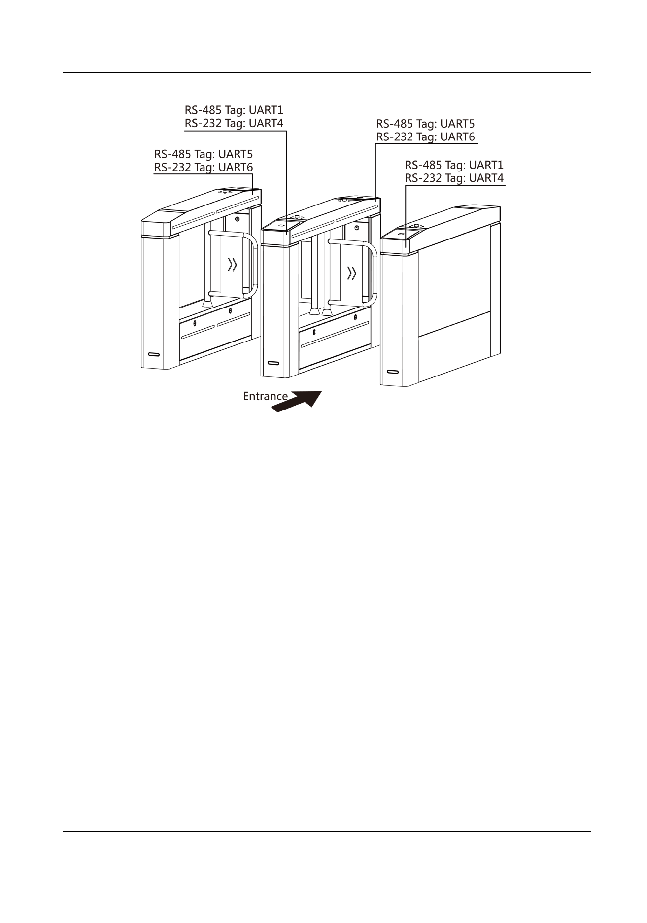
Figure 4-8 Interface and Corresponded UART No.
DS-K3B601SX Series Swing Barrier Quick Start Guide
22
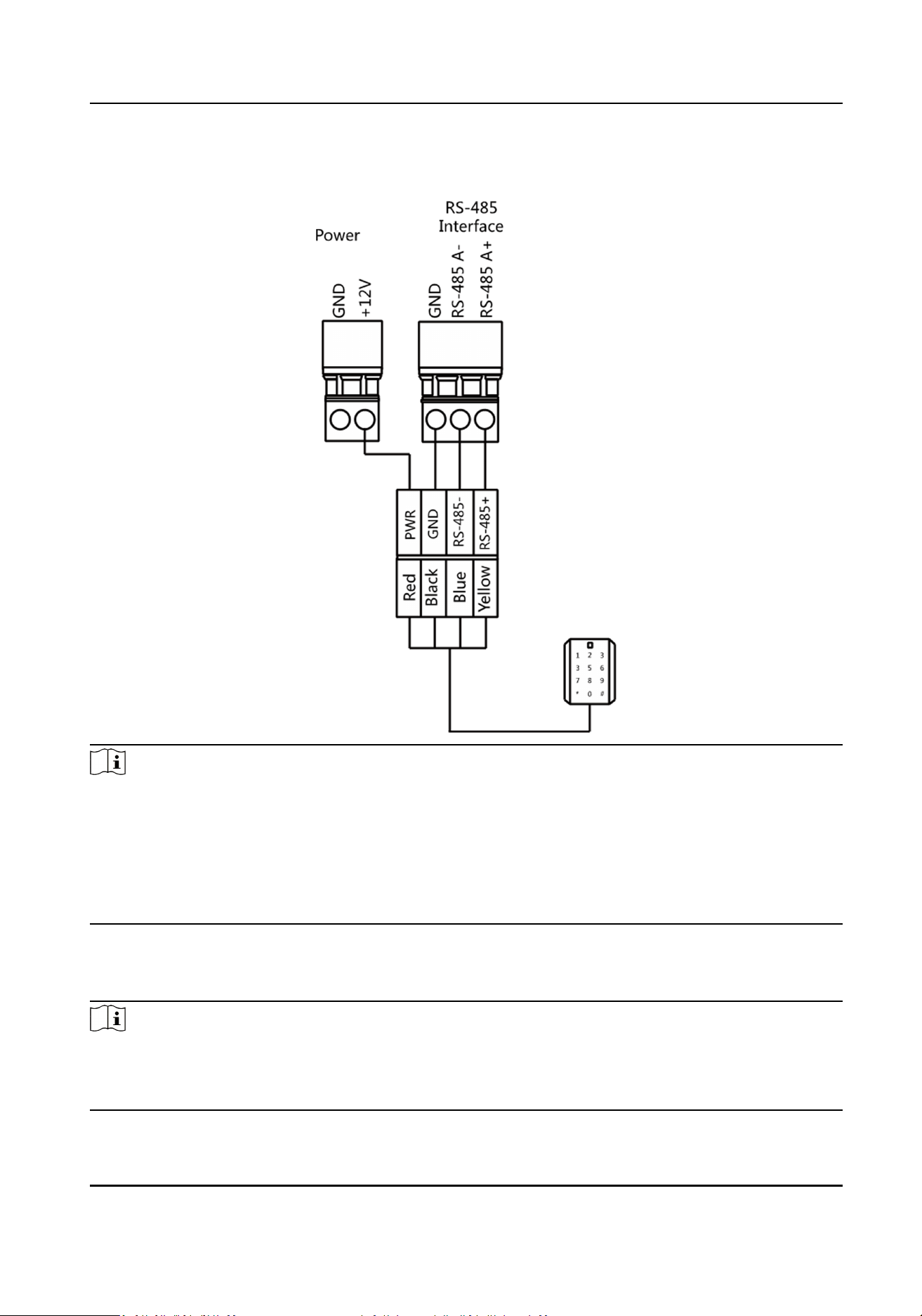
4.5.5 RS-485 Wiring
Note
• There are four RS-485 interfaces, which are for
connecng ID card reader, IC card reader, QR
code scanner, ngerprint and card reader, card recycler, ngerprint reader, and face recognion
terminal. Take the wiring of RS-485 card reader as an example.
• When connecng the RS-485 interface with a card reader, the default entrance address is 1 and
the exit address is 4.
• If there are more than 1 RS-485 devices connected, the RS-485 ID cannot be
conicted.
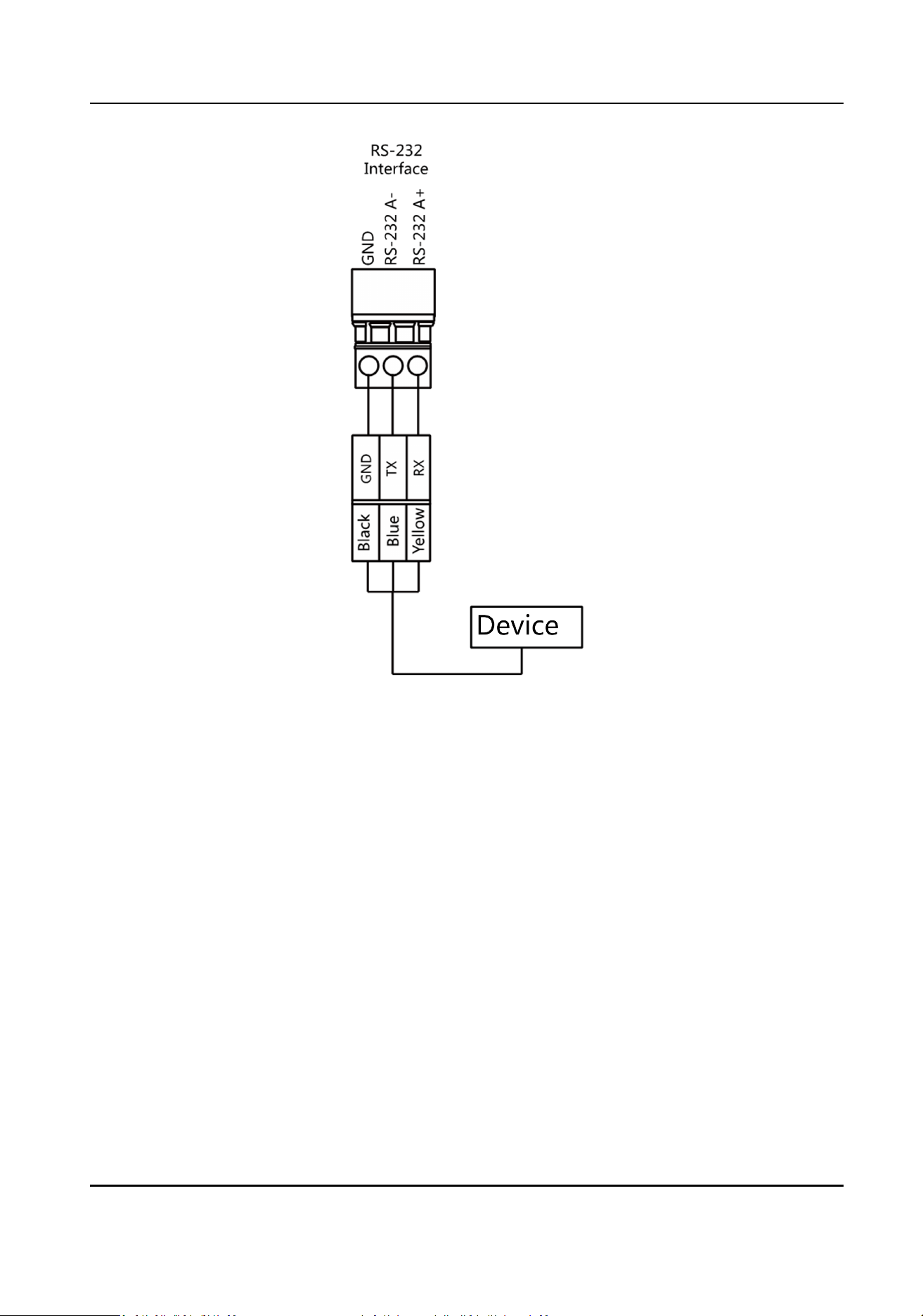
4.5.6 RS-232 Wiring
Note
There are three RS-232 interfaces (UART4, UART7, and UART8). UART7 and UART8 can connect QR
code scanner, and card recycler, while UART4 can connect QR code scanner, card recycler, and face
recognion terminal.
DS-K3B601SX Series Swing Barrier Quick Start Guide
23
DS-K3B601SX Series Swing Barrier Quick Start Guide
24
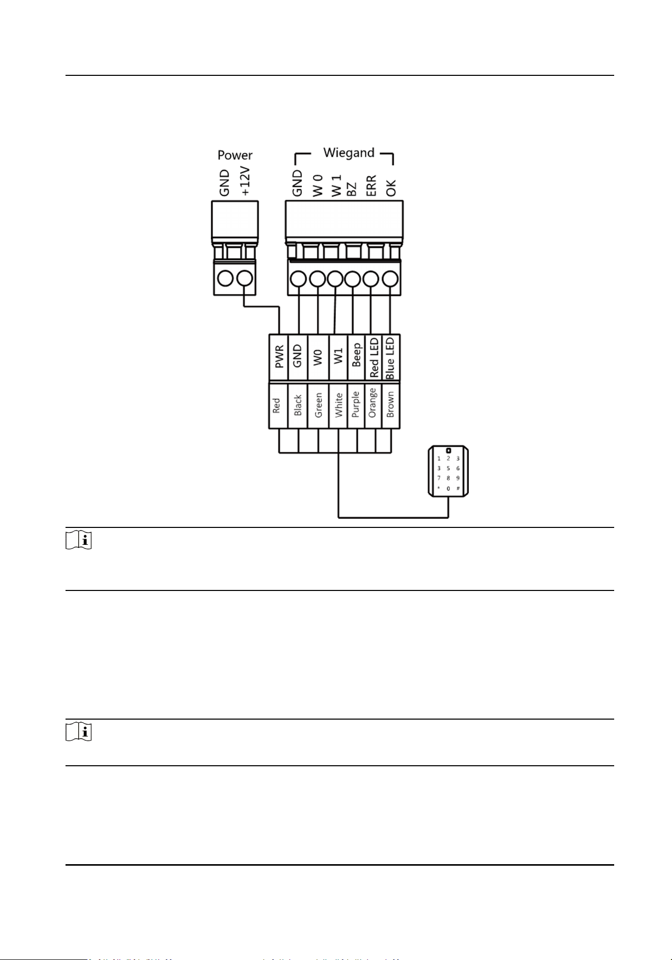
4.5.7 Wiegand Wiring
Note
Connect the OK/ERR/BZ if the access controller should control the LED and buzzer of the Wiegand
card reader.
4.5.8 Barrier Control Wiring
By default, the barrier has connected with the access control board. The lane control board can
control the barrier status. If possible, the device can connect with a third party lane control board
to control the third party barriers. Interface D1 controls barrier opening for entrance, while
interface D2 controls barrier opening for exit.
Note
Use the jumper cap to switch the relay status. For details, see Barrier Control Relay Output Mode .
DS-K3B601SX Series Swing Barrier Quick Start Guide
25
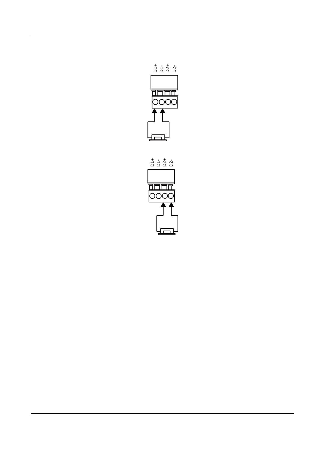
Entering Wiring
Exing Wiring
DS-K3B601SX Series Swing Barrier Quick Start Guide
26
Chapter 5 Device Sengs
Aer installaon and wiring completed, the turnsle will learn the open and closed posion
automacally.
Aer
the learning, the turnsle is in the normal mode. You can also set the turnsle to test mode,
passing mode and memory mode, pair the keyfob, inialize the hardware, switching between
RS-485
communicaon mode and RS-232 communicaon mode, and view relay output NO/NC
diagram by seng the DIP switch on the access control board.
• Study Mode: The barrier will learn the closed
posion.
• Normal Mode: The device will work properly. The device will work properly. The barrier posion
congured in study mode is the closed posion when the device is working normally.
• Test Mode: Test mode is the same as the normal mode except that the device cannot report the
alarm, the event, or the people
counng informaon to the center.
• Passing Mode: There are 9 passing modes, including controlled
bi-direcon, controlled entrance
and prohibited exit, controlled entrance and free exit, free bi-direcon, free entrance and
controlled exit, free entrance and prohibited exit, prohibited bi-direcon, prohibited entrance
and free exit.
• Memory Mode: By default, the memory mode is enabled. When
mulple cards are presented
and authencated, it allows mulple persons passing through the lane. When it counts the
passing people number is equal to the card presented
mes, or no person passing through the
lane aer the last person passing, the barriers will be closed.
Note
You can also set the DIP switch on the access control board to control the entrance and exit
controlling type, keyfob pairing, etc. For details about the DIP switch value, see DIP Switch .
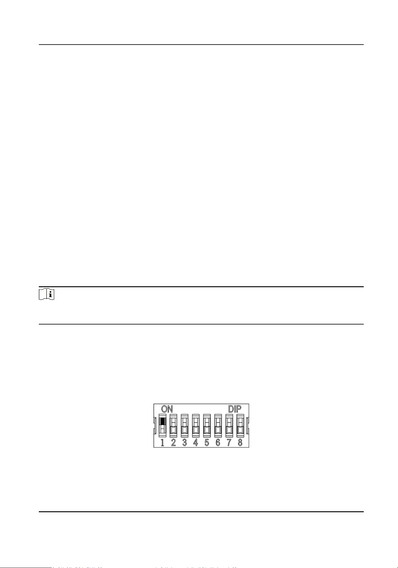
5.1 Set Study Mode
Enter the study mode through DIP switching to set the closed posion of the device barrier.
Steps
1. Set The No.1 of the 8-digit DIP Switch on the main control board to ON by referring the
following
gure to enter the study mode.
2. Adjust the closed posion of the barrier.
3. Power on the device.
The device will remember the current
posion (closed posion) automacally.
DS-K3B601SX Series Swing Barrier Quick Start Guide
28
4. Power
o the device.
5. Set the No.1 switches of the 8-digit DIP Switch on the main control board by referring to the
following gure.
6. Power on the device again.
Note
For details about the DIP switch value and meaning, see DIP Switch Descripon.
The barrier will open automacally and turns back to the closed posion. At this circumstance,
the device enters the normal mode.
5.2 Pair Keyfob
(Oponal)
Pair the remote control to the device through DIP switch to open/close the barrier remotely.
Before You Start
Ask our technique supports or sales and purchase the keyfob.
Steps
Note
Up to 32 keyfobs can be added to the turnsle.
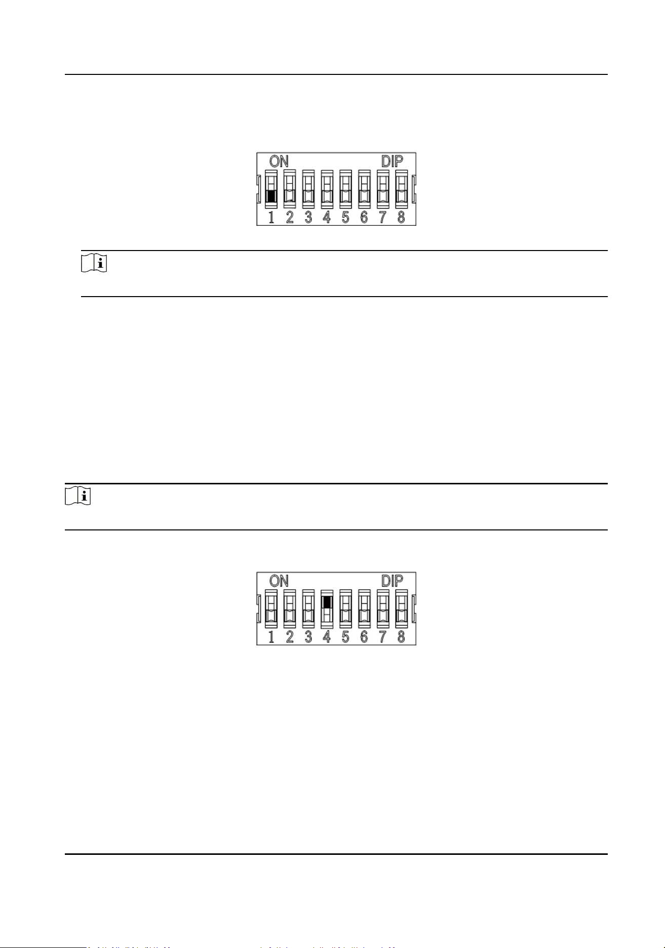
1. Power o the turnsle.
2. Set the No.4 switch of the DIP Switch on the access control board to the ON side.
3. Power on the turnsle and it will enter the keyfob pairing mode.
4. Hold the Close
buon for more than 10 seconds. Or pair turnsle and keyfob in the client
soware, see Manage Keyfob User of the user manual for more details.
The keyfob's indicator of the will
ash twice if the pairing is completed.
5. Set the No.4 switch to OFF, and reboot the turnsle to take eect.
DS-K3B601SX Series Swing Barrier Quick Start Guide
29
Note
• Only one
turnsle can pair the keyfob. If mulple turnsles are in the pairing mode, the
keyfob will select only one of them to pair.
• For details about DIP switch value and meaning, see DIP Switch .
6.
Oponal: Go to System → User → Keyfob User on the remote control page of the client
soware to delete the keyfob.
5.3 Inialize Device
Steps
1. Remove the JP11 jumper cap on the access control board.
Figure 5-1 Inializaon Jumper Cap
2. Disconnect the power and reboot the device. The device buzzer buzzes a long beep.
3. When the beep stopped, plug the jumper cap back.
4. Disconnect the power and power on the device again.
Cauon
The inializaon of the device will restore all the parameters to the default seng and all the
device events are deleted.
DS-K3B601SX Series Swing Barrier Quick Start Guide
30
Note
Make sure no persons are in the lane when powering on the device.
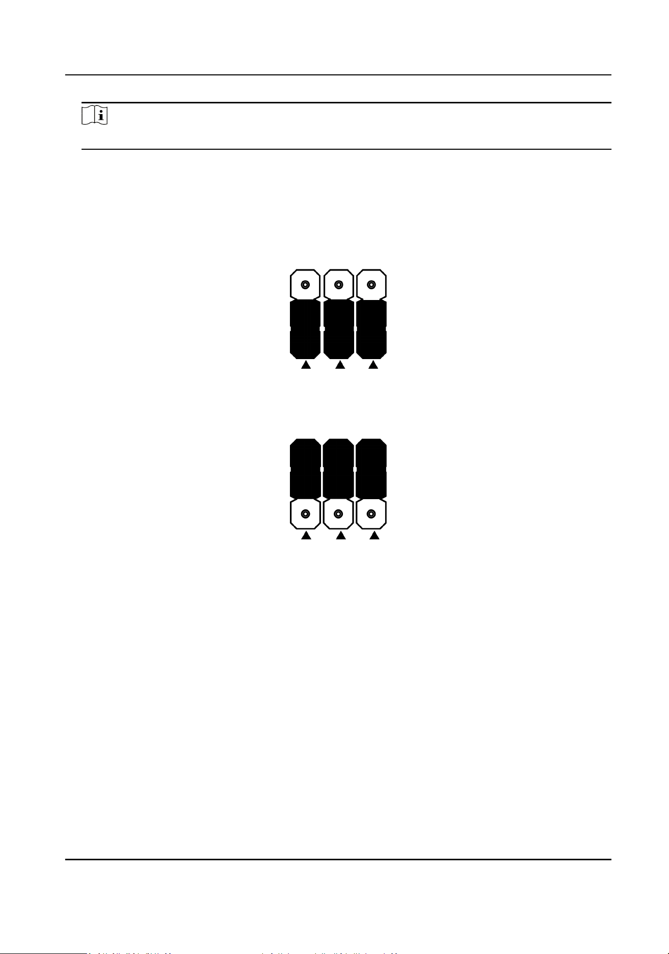
5.4 Switch to RS-485/RS-232 Mode
Take the Serial Port 4 and on the access control board as an example. If the Jumper cap's posion is
like the picture displayed below. (The black part is the jumper cap.) The serial port is in RS-485
communicaon mode.
Figure 5-2 Jumper Cap Status of RS-485 Interface
If the Jumper cap's posion is like the picture displayed below. (The black part is the jumper cap.)
The serial port is in RS-232 communicaon mode.
Figure 5-3 Jumper Cap Status of RS-232 Interface
5.5 Switch Relay Output Mode (NO/NC)
5.5.1 Barrier Control Relay Output Mode
The pins of the barrier control relay on the access control board is as below:
DS-K3B601SX Series Swing Barrier Quick Start Guide
31
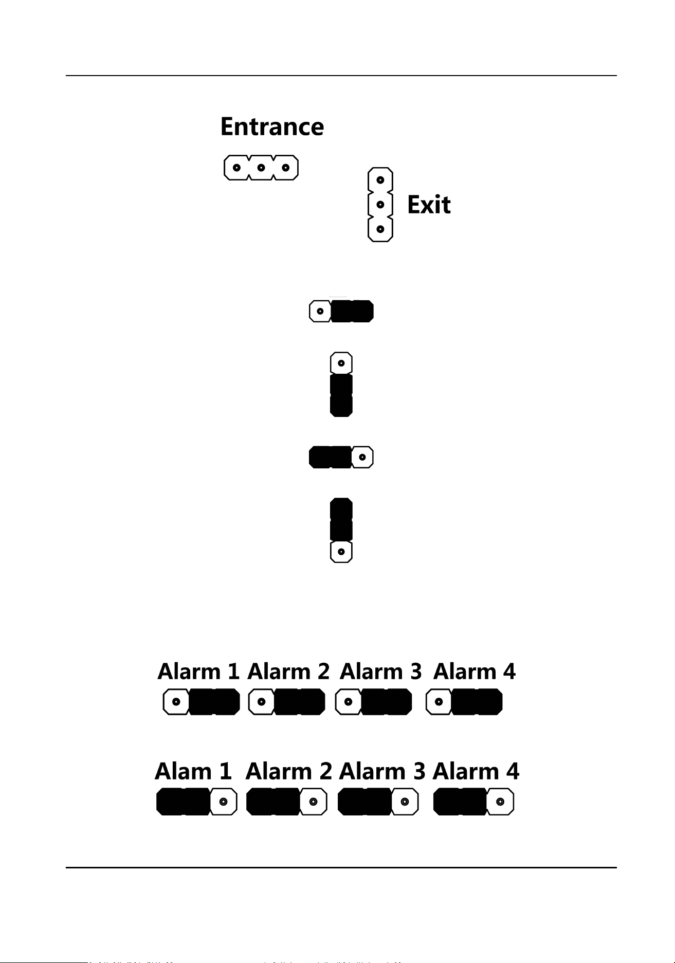
Figure 5-4 Pin Appearance
The jumper cap's posion of barrier opening for entrance (NO) is as below:
The jumper cap's posion of barrier opening for exit (NO) is as below:
The jumper cap's posion of barrier closing for entrance (NC) is as below:
The jumper cap's posion of barrier closing for exit (NC) is as below:
5.5.2 Alarm Relay Output Mode (NO/NC)
Alarm Relay Output Mode (NO):
Alarm Relay Output Mode (NC):
DS-K3B601SX Series Swing Barrier Quick Start Guide
32
Chapter 6 Acvaon
You should acvate the device before the rst login. Aer powering on the device, the system will
switch to Device
Acvaon page.
Acvaon via the device, SADP tool and the client soware are supported.
The default values of the device are as follows:
•
The default IP address: 192.0.0.64
• The default port No.: 8000
• The default user name: admin
6.1
Acvate via SADP
SADP is a tool to detect, acvate and modify the IP address of the device over the LAN.
Before You Start
• Get the SADP soware from the supplied disk or the ocial website hp://
www.hikvision.com/en/ , and install the SADP according to the prompts.
• The device and the PC that runs the SADP tool should be within the same subnet.
The following steps show how to acvate a device and modify its IP address. For batch acvaon
and IP addresses modicaon, refer to User Manual of SADP for details.
Steps
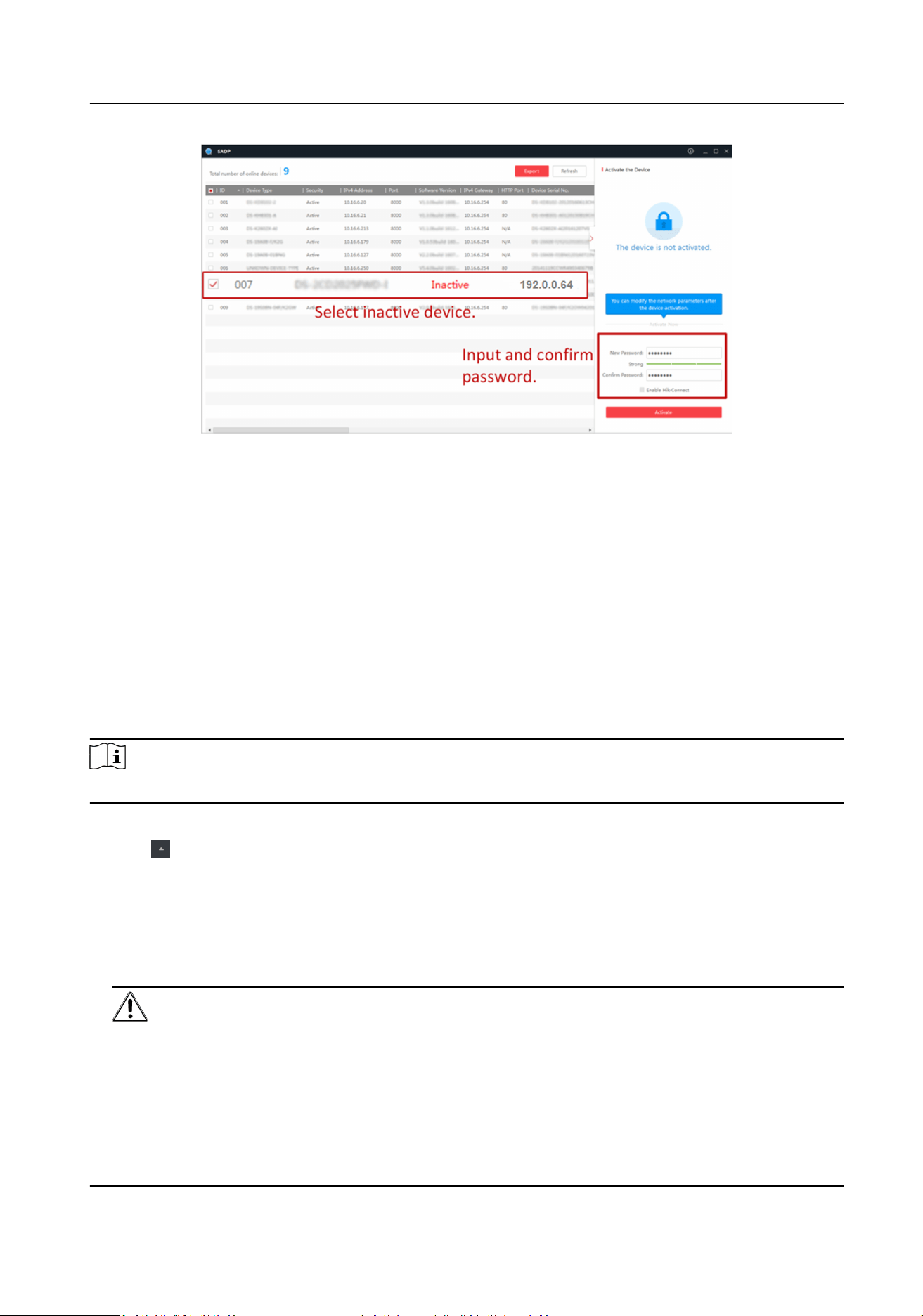
1. Run the SADP soware and search the online devices.
2. Find and select your device in online device list.
3. Input new password (admin password) and
conrm the password.
Cauon
STRONG PASSWORD RECOMMENDED-We highly recommend you create a strong password of
your own choosing (using a minimum of 8 characters, including upper case leers, lower case
leers, numbers, and special characters) in order to increase the security of your product. And
we recommend you reset your password regularly, especially in the high security system,
reseng the password monthly or weekly can beer protect your product.
4. Click Acvate to start acvaon.
DS-K3B601SX Series Swing Barrier Quick Start Guide
33
Status of the device becomes Acve aer successful acvaon.
5. Modify IP address of the device.
1) Select the device.
2) Change the device IP address to the same subnet as your computer by either modifying the
IP address manually or checking Enable DHCP.
3) Input the admin password and click Modify to
acvate your IP address modicaon.
6.2
Acvate Device via Client Soware
For some devices, you are required to create the password to acvate them before they can be
added to the
soware and work properly.
Steps
Note
This funcon should be supported by the device.
1. Enter the Device Management page.
2. Click on the right of Device Management and select Device.
3. Click Online Device to show the online device area.
The searched online devices are displayed in the list.
4. Check the device status (shown on Security Level column) and select an
inacve device.
5. Click
Acvate to open the Acvaon dialog.
6. Create a password in the password eld, and conrm the password.
Cauon
The password strength of the device can be automacally checked. We highly recommend you
change the password of your own choosing (using a minimum of 8 characters, including at least
DS-K3B601SX Series Swing Barrier Quick Start Guide
34

three kinds of following categories: upper case leers, lower case leers, numbers, and special
characters) in order to increase the security of your product. And we recommend you change
your password regularly, especially in the high security system, changing the password monthly
or weekly can
beer protect your product.
Proper
conguraon of all passwords and other security sengs is the responsibility of the
installer and/or end-user.
7. Click OK to acvate the device.
DS-K3B601SX Series Swing Barrier Quick Start Guide
35
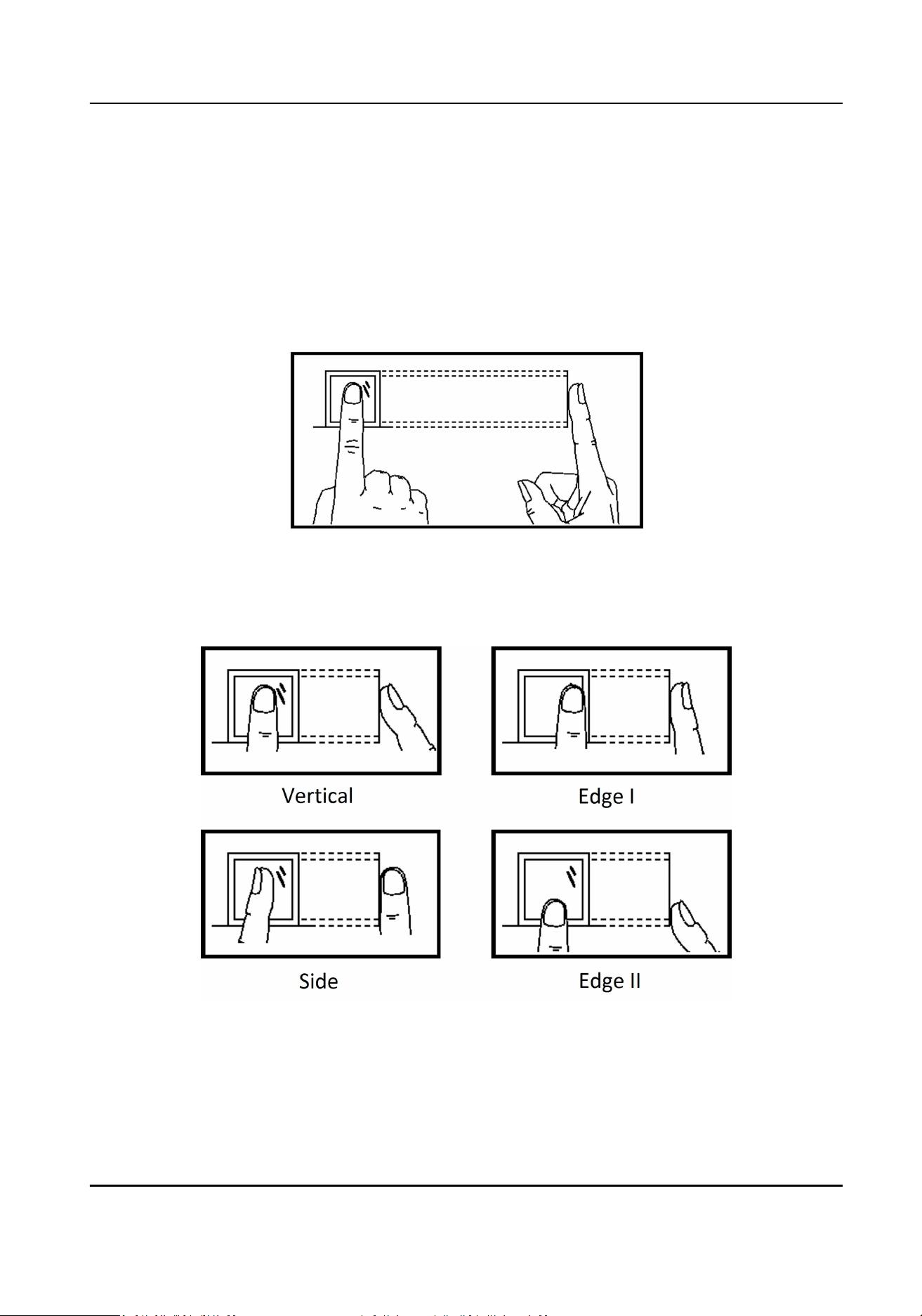
Appendix A. Tips for Scanning Fingerprint
Recommended Finger
Forenger, middle nger or the third nger.
Correct Scanning
The gure displayed below is the correct way to scan your nger:
You should press your nger on the scanner horizontally. The center of your scanned nger should
align with the scanner center.
Incorrect Scanning
The gures of scanning ngerprint displayed below are incorrect:
Environment
The scanner should avoid direct sun light, high temperature, humid condions and rain.
When it is dry, the scanner may not recognize your ngerprint successfully. You can blow your
nger and scan again.
DS-K3B601SX Series Swing Barrier Quick Start Guide
36

Others
If your ngerprint is shallow, or it is hard to scan your ngerprint, we recommend you to use other
authencaon methods.
If you have injuries on the scanned nger, the scanner may not recognize. You can change another
nger and try again.
DS-K3B601SX Series Swing Barrier Quick Start Guide
37
Appendix B. DIP Switch
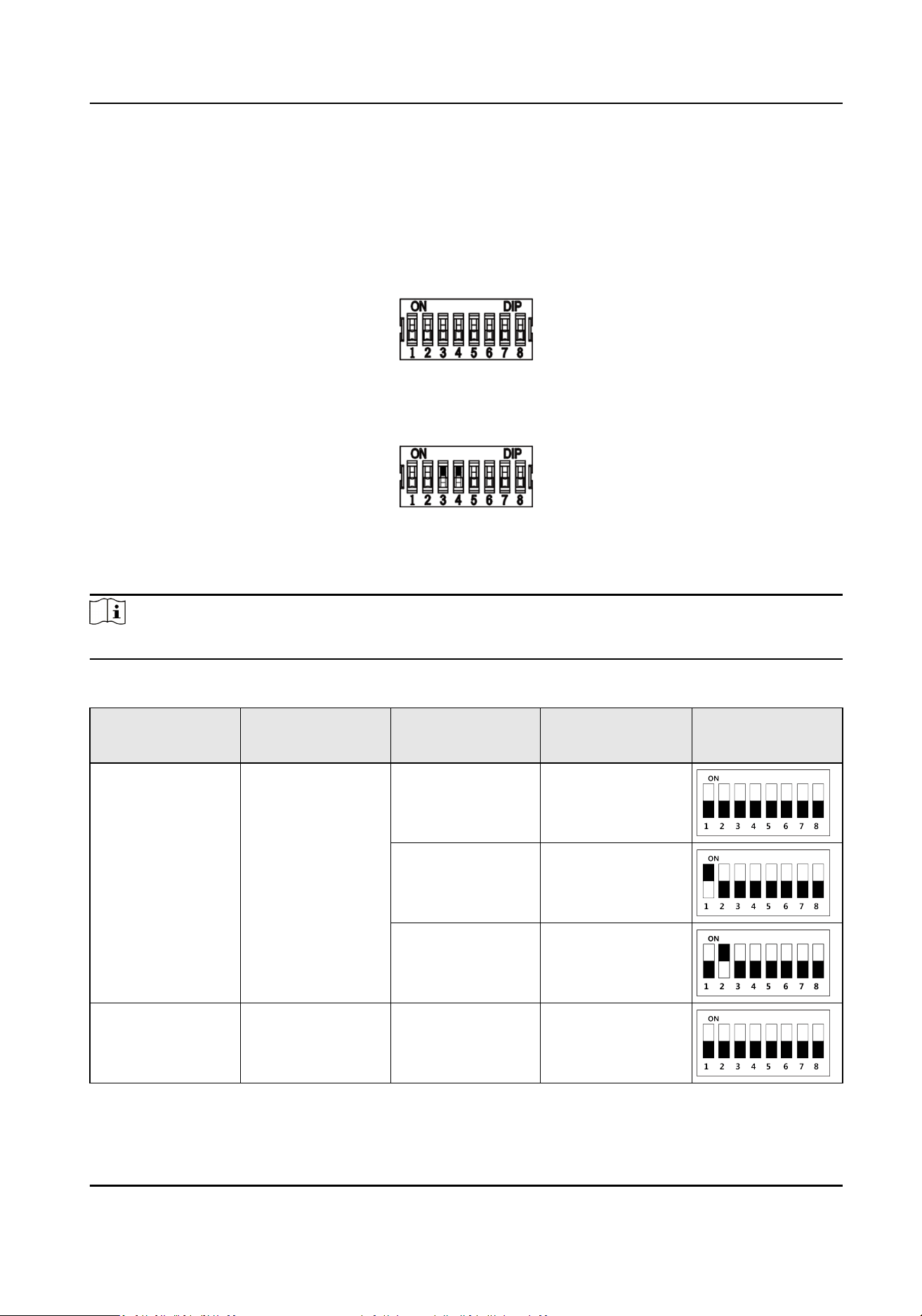
B.1 DIP Switch Descripon
The DIP switch is on the main lane control board. No.1 to No 8 is from the low bit to the high bit.
When the switch is towards ON, it means the switch is enabled, otherwise, the switch is o. If you
set the DIP switch like the gure displayed below, its binary value is 00001100, and its decimal
value is 12.
B.2 DIP Switch Corresponded
Funcons
Note
Aer seng the DIP switch, you should reboot the device, or the funcon cannot take eect.
The 8-bit DIP switch corresponded funcons on the access control board are as follows:
Bit
Device Mode Funcon Decimal Value DIP Switch
Address Diagram
1 to 2 Work Mode Normal Mode 0
Study Mode 1
Test Mode 2
3 Memory Mode Enable Memory
Mode
0
DS-K3B601SX Series Swing Barrier Quick Start Guide
38
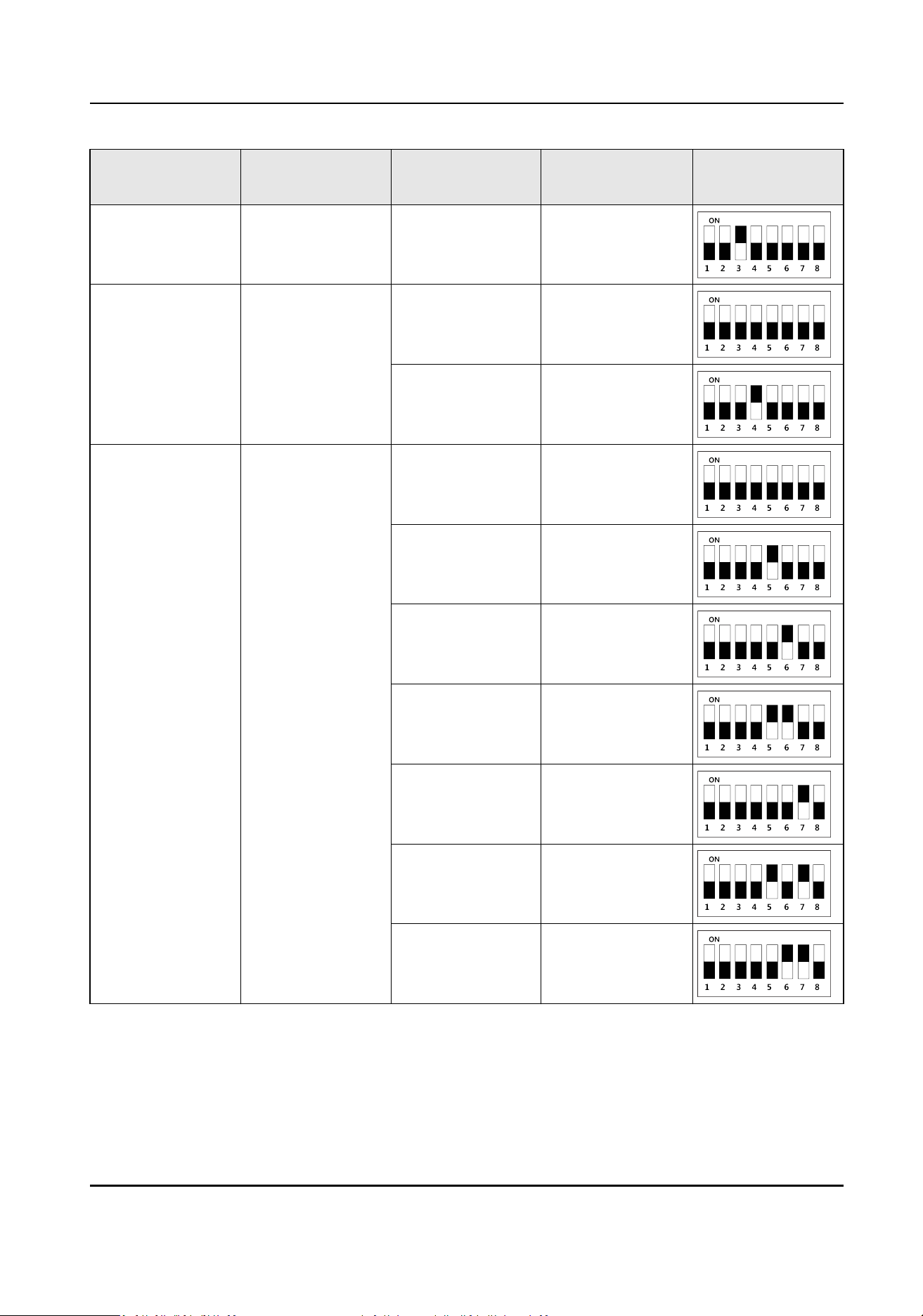
Bit Device Mode Funcon Decimal Value DIP Switch
Address Diagram
Disable Memory
Mode
1
4 Keyfob Paring
Mode
Disable Keyfob
Paring Mode
0
Enable Keyfob
Paring Mode
1
5 to 8 Passing Mode Controlled Bi-
direcon
0
Controlled
Entrance and
Prohibit Exit
1
Controlled
Entrance and Free
Exit
2
Free Bi-direcon 3
Free Entrance and
Controlled Exit
4
Free Entrance and
Prohibit Exit
5
Prohibited Bi-
direcon
6
DS-K3B601SX Series Swing Barrier Quick Start Guide
39

Bit Device Mode Funcon Decimal Value DIP Switch
Address Diagram
Prohibit Entrance
and Controlled
Exit
7
Prohibit Entrance
and Free Exit
8
DS-K3B601SX Series Swing Barrier Quick Start Guide
40
Appendix C. Event and Alarm Type
Event Alarm Type
Tailgang Visual and Audible
Reverse Passing Visual and Audible
Force Accessing None
Climb over Barrier Visual and Audible
Overstay Visual and Audible
Passing Timeout None
Intrusion Visual and Audible
Free Passing
Authencaon Failed
Visual
Barrier Obstructed None
DS-K3B601SX Series Swing Barrier Quick Start Guide
41
Appendix D. Table of Audio Index Related Content
Index Content
1 Authencated.
2 Card No. does not exist.
3 Card No. and ngerprint mismatch.
4 Climbing over the barrier.
5 Reverse passing.
6 Passing meout.
7 Intrusion.
8 Force accessing.
9 Tailgang.
10 No permissions.
11 Authencaon me out.
12 Authencaon failed.
13 Expired card.
14 Staying out of me.
DS-K3B601SX Series Swing Barrier Quick Start Guide
42
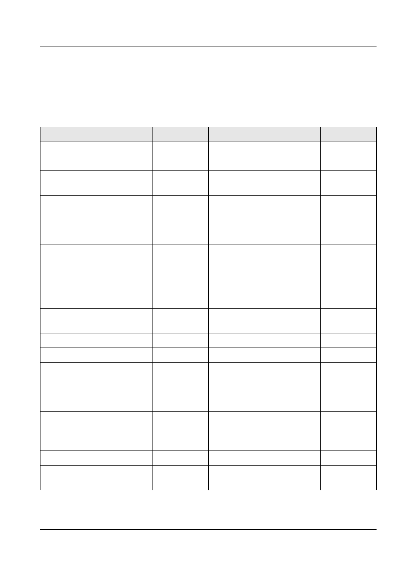
Appendix E. Error Code Descripon
The swing barrier will display the error code on the seven-segment display if error occurred. Refer
to the table below to
nd the descripon of each number.
Error Reason Code Error Reason Code
Normal Working 00 Lower Fih IR Beam Triggered 17
Upper First IR Beam Triggered 01 Lower Sixth IR Beam Triggered 18
Upper Second IR Beam
Triggered
02 Lower Seventh IR Beam
Triggered
19
Upper Third IR Beam Triggered 03 Lower Eighth IR Beam
Triggered
20
Upper Fourth IR Beam
Triggered
04 Lower Ninth IR Beam Triggered 21
Upper Fih IR Beam Triggered 05 Lower Tenth IR Beam Triggered 22
Upper Sixth IR Beam Triggered 06 Lower Eleventh IR Beam
Triggered
23
Upper Seventh IR Beam
Triggered
07 Lower Twelh IR Beam
Triggered
24
Upper Eighth IR Beam
Triggered
08 Light Board Oine (Entrance) 49
Upper Ninth IR Beam Triggered 09 Light Board Oine (Exit) 50
Upper Tenth IR Beam Triggered 10 IR Adapter Oine (Up) 51
Upper Eleventh IR Beam
Triggered
11 IR Adapter Oine (Low) 52
Upper Twelh IR Beam
Triggered
12 CAN Bus Excepon 53
Lower First IR Beam Triggered 13 Not Studying 54
Lower Second IR Beam
Triggered
14 Obstrucon 55
Lower Third IR Beam Triggered 15 Exceeding Studying Range 56
Lower Fourth IR Beam
Triggered
16 Motor Excepon 57
DS-K3B601SX Series Swing Barrier Quick Start Guide
43
Appendix F. Communicaon Matrix and Device
Command
Communicaon Matrix
Scan the following QR code to get the device communicaon matrix.
Note that the matrix contains all communicaon ports of Hikvision access control and video
intercom devices.
Figure F-1 QR Code of Communicaon Matrix
Device Command
Scan the following QR code to get the device common serial port commands.
Note that the command list contains all commonly used serial ports commands for all Hikvision
access control and video intercom devices.
Figure F-2 Device Command
DS-K3B601SX Series Swing Barrier Quick Start Guide
44

UD23130B-D