Loading ...
Loading ...
Loading ...
En-7
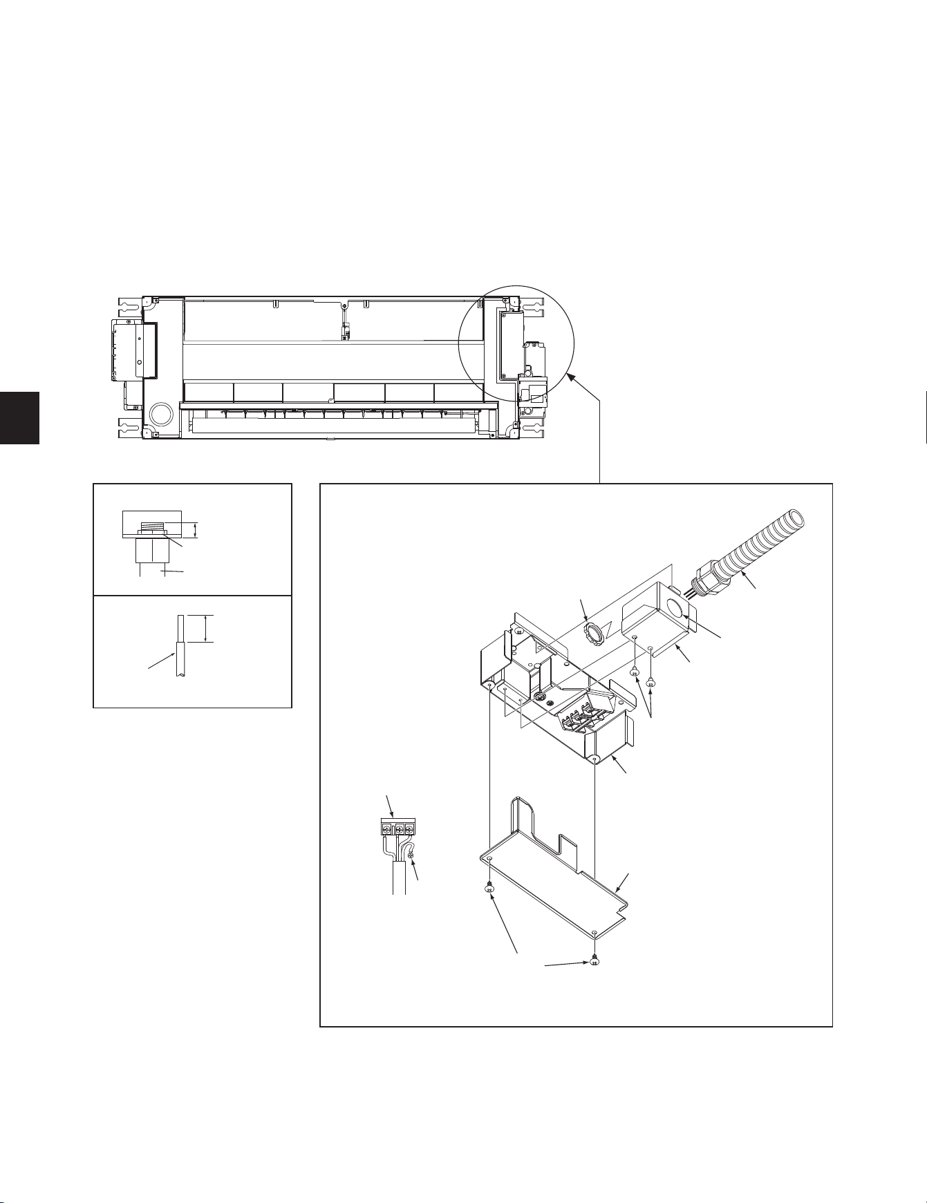
2-4. CONNECTING WIRES FOR INDOOR UNIT
Note: The unit should be installed by a licensed contractor/electrician. If required by applicable national, state and local codes; a disconnect switch will need to be installed
when the indoor unit is powered from the outdoor unit.
1) Remove the electrical cover (1).
2) Remove the conduit plate.
3) Attach the conduit pipe to the conduit plate with the lock nut. The indoor/outdoor unit connecting wire
D appearing from the inside of conduit pipe should be less than
7/8 in. (23 mm). (Fig. 1)
4) Process the end of ground wire (Fig. 2). Connect it to the ground terminal of the electrical parts box.
5) Process the end of indoor/outdoor unit connecting wire
D (Fig. 2). Attach it to the terminal block. Be careful not to make mis-wiring. Attach the wire to the terminal block
securely so that its core cannot be seen, and no external force affects the connecting section of the terminal block.
6) Firmly tighten the terminal screws. After tightening, verify that the wires are tightly fastened.
7) Reinstall the conduit plate.
• For future servicing, give extra length to the connecting wires.
• Do not fold the excess wire, or cram it into small space. Take caution not to damage the wires.
• Be sure to attach each screw to its correspondent terminal when securing the cord and/or the wire to the terminal block.
Fig. 1
Lead
wire
9/16 in.
(15 mm)
Fig. 2
Terminal block
Lock nut
Electrical box
Grounding
terminal
Screw
Less than 7/8 in.
(23 mm)
Conduit plate
Conduit pipe
Lock nut
Conduit plate
Conduit pipe
Electrical cover (1)
Screw
ø
7/8 in.
(ø22.2 mm)
BH79A643H01_01En.indd 7 2021/05/06 17:37:22
Loading ...
Loading ...
Loading ...