Loading ...
Loading ...
En-2
1-2. SELECTING THE INSTALLATION LOCATION
INDOOR UNIT
• Whereairowisnotblocked.
• Where cool (or warm) air spreads over the entire room.
• Where it is not exposed to direct sunshine. Do not expose to direct sunshine also
during the period following unpacking to before use.
• Where easily drained.
• At a distance 3 ft. (1 m) or more away from your TV and radio. Operation of the air
conditionermayinterferewithradioorTVreception.Anampliermayberequired
for the affected device.
•
Inaplaceasfarawayaspossiblefromuorescentandincandescentlights.Inorder
to make the infrared remote control operate the air conditioner normally. The heat
from the lights may cause deformation or the ultraviolet may cause deterioration.
• Wheretheairltercanberemovedandreplacedeasily.
• Where it is away from the other heat or steam source.
REMOTE CONTROLLER
• Where it is easy to operate and easily visible.
• Where children cannot touch it.
• Selectapositionabout4ft.(1.2m)abovetheoorandcheckthatsignalsfromthe
remote controller are surely received by the indoor unit from that position (‘beep’
or ‘beep beep’ receiving tone sounds). After that, attach remote controller holder
to a pillar or wall and install wireless remote controller.
Note:
Inroomswhereinvertertypeuorescentlampsareused,thesignalfromthewire-
less remote controller may not be received.
Note:
Avoid the following places for installation where air conditioner trouble is liable
to occur.
• Whereammablegascouldleak.
• Where there is much machine oil.
• Whereoilissplashedorwheretheareaislledwithoilysmoke(suchascooking
areas and factories, in which the properties of plastic could be changed and
damaged).
• Salty places such as the seaside.
• Wheresuldegasisgeneratedsuchashotspring,sewage,wastewater.
• Where there is high-frequency or wireless equipment.
• Where there is emission of high levels of VOCs, including phthalate compounds,
formaldehyde, etc., which may cause chemical cracking.
• The appliance shall be stored so as to prevent mechanical damage from oc-
curring.
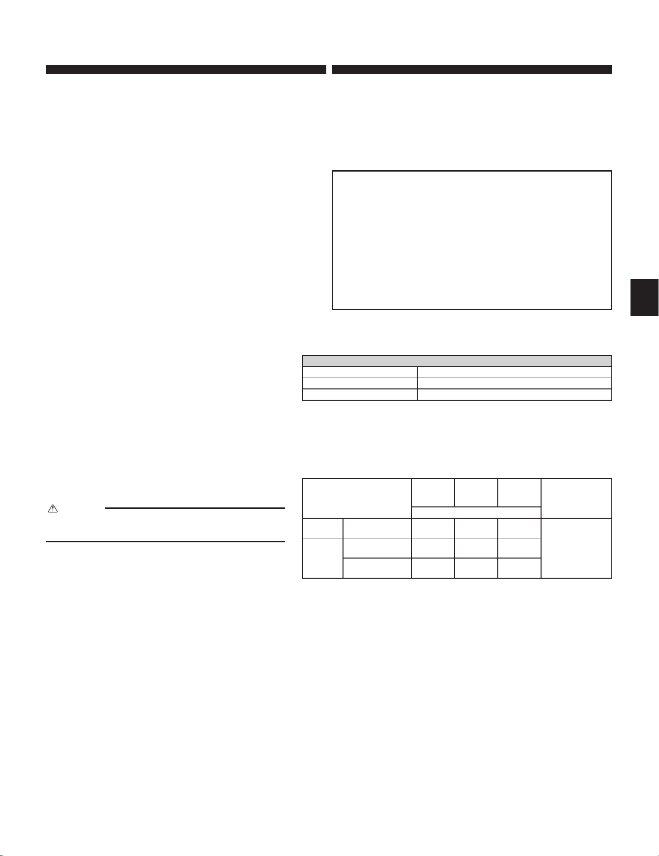
Electrical specications
INDOOR UNIT
Power supply (V, PHASE, Hz) 208/230, 1, 60
Min. Circuit Ampacity (A) 1.0
Fan motor (F.L.A.) (A) 0.68
Pipe
Outside
diameter
Minimum
wall thick-
ness
Insulation
thickness
Insulation material
inch (mm)
For liquid
MLZ-
KP09/12/18NA2
1/4 (6.35)
0.0315
(0.8)
5/16 (8)
Heat resistant
foam plastic 0.045
Specicgravity
For gas
MLZ-KP09/12NA2 3/8 (9.52)
0.0315
(0.8)
5/16 (8)
MLZ-KP18NA2 1/2 (12.7)
0.0315
(0.8)
5/16 (8)
1-3. SPECIFICATIONS
1-3-1. INDOOR/OUTDOOR WIRE CONNECTION
•
Wiring work should be based on applicable technical standards.
• Wiring connections should be made following the diagram.
• Securely tighten screws.
Connecting wires and the ground wire
• Use solid conductor Min. AWG14 or stranded conductor Min. AWG14.
• Use double insulated copper wire with 600 V insulation.
• Use copper conductors only.
* Follow local electrical codes.
Note:
When the indoor unit is powered from the outdoor unit, depending
on local code, a disconnect switch needs to be installed to a power
supply circuit.
1-3-2. REFRIGERANT PIPES
• To prevent condensation, insulate the two refrigerant pipes.
CAUTION
Besuretousetheinsulationofspeciedthickness(tableontheright).
Excessive insulation may cause incorrect installation of the indoor unit,
and too little insulation may cause condensate to form.
• Theunithasaredconnectionsonbothindoorandoutdoorsides.
• Remove the valve cover from the outdoor unit, then connect the pipe.
• Refrigerant pipes are used to connect the indoor and outdoor units.
• Be careful not to crush or over bend the pipe in pipe bending.
BH79A643H01_01En.indd 2 2021/05/06 17:37:19
Loading ...
Loading ...
Loading ...