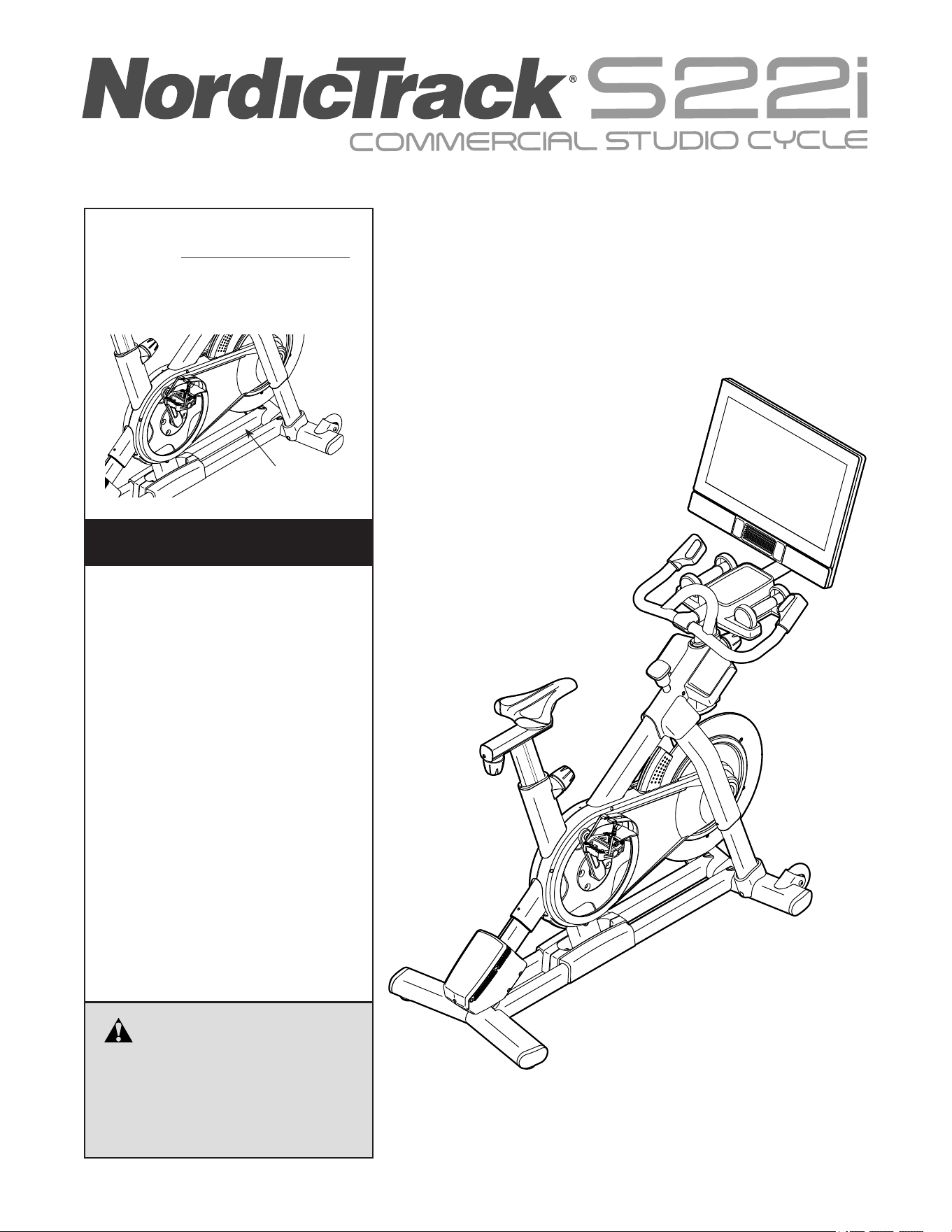
USER’S MANUAL
Model No. NTEX02422-INT.3
Serial No.
Write the serial number in the space
above for reference.
CAUTION
Read all precautions and
instructions in this manual before
using this equipment. Keep this
manual for future reference.
iconeurope.com
Serial Number
Decal
MEMBER CARE
UNITED KINGDOM
Website: iconsupport.eu
E-mail: [email protected]
Write:
ICON Health & Fitness, Ltd.
Unit 4, Westgate Court
Silkwood Park
OSSETT
WF5 9TT
UNITED KINGDOM
AUSTRALIA
Call: 1800 993 770
E-mail: [email protected]
Write:
iFIT Inc.
PO Box 635
WINSTON HILLS NSW 2153
AUSTRALIA
2
WARNING DECAL PLACEMENT . . . . . . . . . . . . . . . . . . . . . . . . . . . . . . . . . . . . . . . . . . . . . . . . . . . . . . . . . . . . . . .2
IMPORTANT PRECAUTIONS ..................................................................3
BEFORE YOU BEGIN. . . . . . . . . . . . . . . . . . . . . . . . . . . . . . . . . . . . . . . . . . . . . . . . . . . . . . . . . . . . . . . . . . . . . . . .4
PART IDENTIFICATION CHART. . . . . . . . . . . . . . . . . . . . . . . . . . . . . . . . . . . . . . . . . . . . . . . . . . . . . . . . . . . . . . . .5
ASSEMBLY . . . . . . . . . . . . . . . . . . . . . . . . . . . . . . . . . . . . . . . . . . . . . . . . . . . . . . . . . . . . . . . . . . . . . . . . . . . . . . . .6
HOW TO USE THE STUDIO CYCLE ...........................................................14
HOW TO USE THE CONSOLE. . . . . . . . . . . . . . . . . . . . . . . . . . . . . . . . . . . . . . . . . . . . . . . . . . . . . . . . . . . . . . . .18
MAINTENANCE AND TROUBLESHOOTING .....................................................30
EXERCISE GUIDELINES ....................................................................34
PART LIST. . . . . . . . . . . . . . . . . . . . . . . . . . . . . . . . . . . . . . . . . . . . . . . . . . . . . . . . . . . . . . . . . . . . . . . . . . . . . . . .35
EXPLODED DRAWING. . . . . . . . . . . . . . . . . . . . . . . . . . . . . . . . . . . . . . . . . . . . . . . . . . . . . . . . . . . . . . . . . . . . . .37
ORDERING REPLACEMENT PARTS. . . . . . . . . . . . . . . . . . . . . . . . . . . . . . . . . . . . . . . . . . . . . . . . . . . Back Cover
RECYCLING INFORMATION ......................................................... Back Cover
TABLE OF CONTENTS
NORDICTRACK and IFIT are registered trademarks of iFIT Inc. The Bluetooth
®
word mark and logos are regis-
tered trademarks of Bluetooth SIG, Inc. and are used under license. Google Maps is a trademark of Google LLC.
Wi-Fi is a registered trademark of Wi-Fi Alliance. WPA and WPA2 are trademarks of Wi-Fi Alliance.
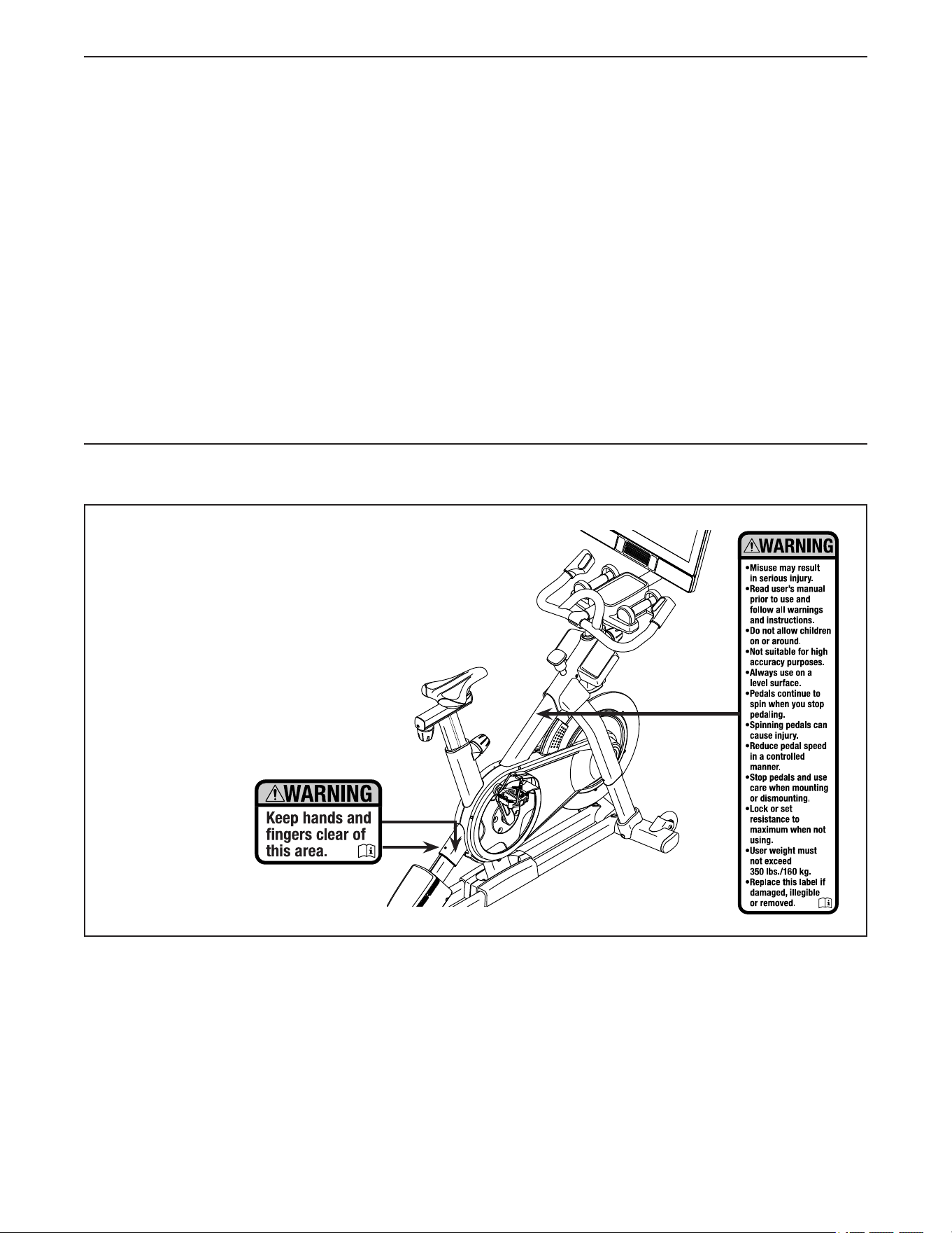
WARNING DECAL PLACEMENT
This drawing shows the location(s) of the warning
decal(s). If a decal is missing or illegible, see
the front cover of this manual and request a
free replacement decal. Apply the decal in
the location shown. Note: The decal(s) may
not be shown at actual size.

3
IMPORTANT PRECAUTIONS
WARNING: To reduce the risk of serious injury, read all important precautions and
instructions in this manual and all warnings on your studio cycle before using your studio cycle. iFIT
assumes no responsibility for personal injury or property damage sustained by or through the use of
this product.
1. It is the responsibility of the owner to
ensure that all users of the studio cycle are
adequately informed of all precautions.
2. Keep children under age 16 and pets away
from the studio cycle at all times.
3. Consult your health care provider before
beginning any exercise program. This is
especially important for persons over age 35
or persons with pre-existing health problems.
4. Consult your health care provider before
beginning or continuing any exercise pro-
gram during pregnancy. Use the studio
cycle only as authorized by your health care
provider.
5. The studio cycle is not intended for use by
persons with reduced physical, sensory, or
mental capabilities or lack of experience and
knowledge, unless they are given supervi-
sion or instruction about the use of the
studio cycle by someone responsible for
their safety.
6. Use the studio cycle only as described in this
manual.
7. The studio cycle is intended for home use
only. Do not use the studio cycle in a com-
mercial, rental, or institutional setting.
8. Keep the studio cycle indoors, away from
moisture and dust. Do not put the studio
cycle in a garage or covered patio, or near
water.
9. Place the studio cycle on a level surface,
with a mat beneath it to protect the floor or
carpet. Make sure that there is at least 2 ft.
(0.6 m) of clearance around the studio cycle.
10. Inspect and properly tighten all parts each
time the studio cycle is used. Replace
any worn parts immediately. Use only
manufacturer-supplied parts.
11. Always plug the power adapter into the
studio cycle before you plug it into an outlet.
12. The studio cycle should not be used by
persons weighing more than 350 lbs.
(160 kg).
13. Wear appropriate clothes while exercising;
do not wear loose clothes that could become
caught on the studio cycle. Always wear ath-
letic shoes for foot protection.
14. Be careful when mounting and dismounting
the studio cycle.
15. Always keep your back straight while using
the studio cycle; do not arch your back.
16. The studio cycle does not have a freewheel;
the pedals will continue to move until the
flywheel stops. Reduce your pedaling speed
in a controlled way.
17. To stop the flywheel quickly, press the brake
knob downward.
18. When the studio cycle is not in use, press the
brake knob downward and tighten it firmly.
19. Over exercising may result in serious injury
or death. If you feel faint, if you become short
of breath, or if you experience pain while
exercising, stop immediately and cool down.
4
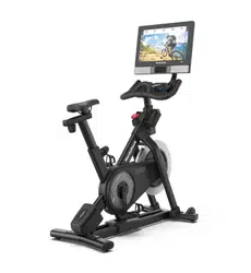
Congratulations for selecting the revolutionary
NORDICTRACK
®
COMMERCIAL S22I STUDIO
CYCLE. The COMMERCIAL S22I STUDIO CYCLE is
unlike any ordinary exercise bike.
With full adjustability, an interactive wireless touch-
screen console, an incline system that simulates
real-world terrain, and an array of other features, the
COMMERCIAL S22I STUDIO CYCLE provides an
immersive in-home studio cycling experience.
For your benefit, read this manual carefully before
you use the studio cycle. If you have questions after
reading this manual, please see the front cover of this
manual. To help us assist you, note the product model
number and serial number before contacting us. The
model number and the location of the serial number
decal are shown on the front cover of this manual.
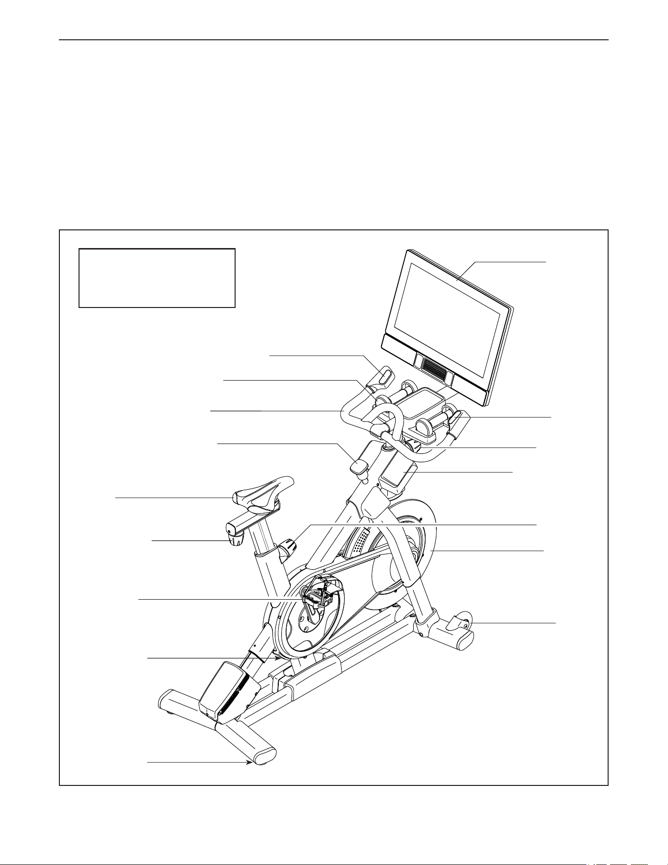
Before reading further, please familiarize yourself with
the parts that are labeled in the drawing below.
Carriage Knob
Post Knob
Post Knob
Pedal/Strap
Flywheel
BEFORE YOU BEGIN
Wheel
Leveling Foot
Length: 4 ft. 10 in. (147 cm)
Width: 1 ft. 10 in. (56 cm)
Weight: 176 lbs. (80 kg)
Saddle
Console
Accessory Tray
Resistance
Control
Brake Knob
Hand Weight
Handlebar
Incline/Decline Control
Power Switch
5
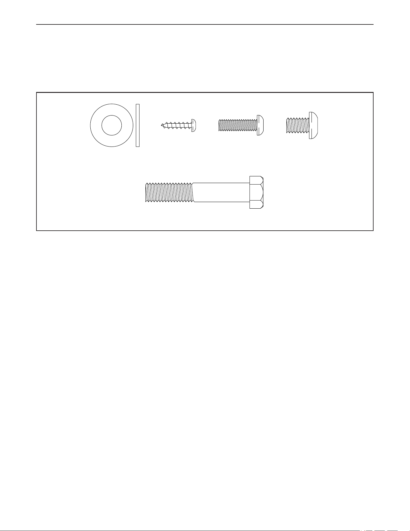
PART IDENTIFICATION CHART
Use the drawings below to identify the small parts needed for assembly. The number in parentheses below each
drawing is the key number of the part, from the PART LIST near the end of this manual. The number following the
key number is the quantity needed for assembly. Note: If a part is not in the hardware kit, check to see if it
has been preassembled. Extra parts may be included.
M10 x 20mm
Screw (105)–4
M10 x 55mm Screw (94)–1
M8 x 12mm
Patch Screw
(93)–4
M4 x 10mm
Machine
Screw (103)–2
#8 x 5/8"
Screw (17)–8
M10 x 35mm
Screw (160)–8
M10 Washer
(161)–1
M6 x 20mm
Machine
Screw (102)–4
M10 x 55mm Screw (94)–1
M8 x 12mm
Patch Screw
(93)–4
M10 Washer
(3)–1
M6 x 20mm
Machine
Screw (102)–4
#8 x 5/8"
Screw (17)–8
6
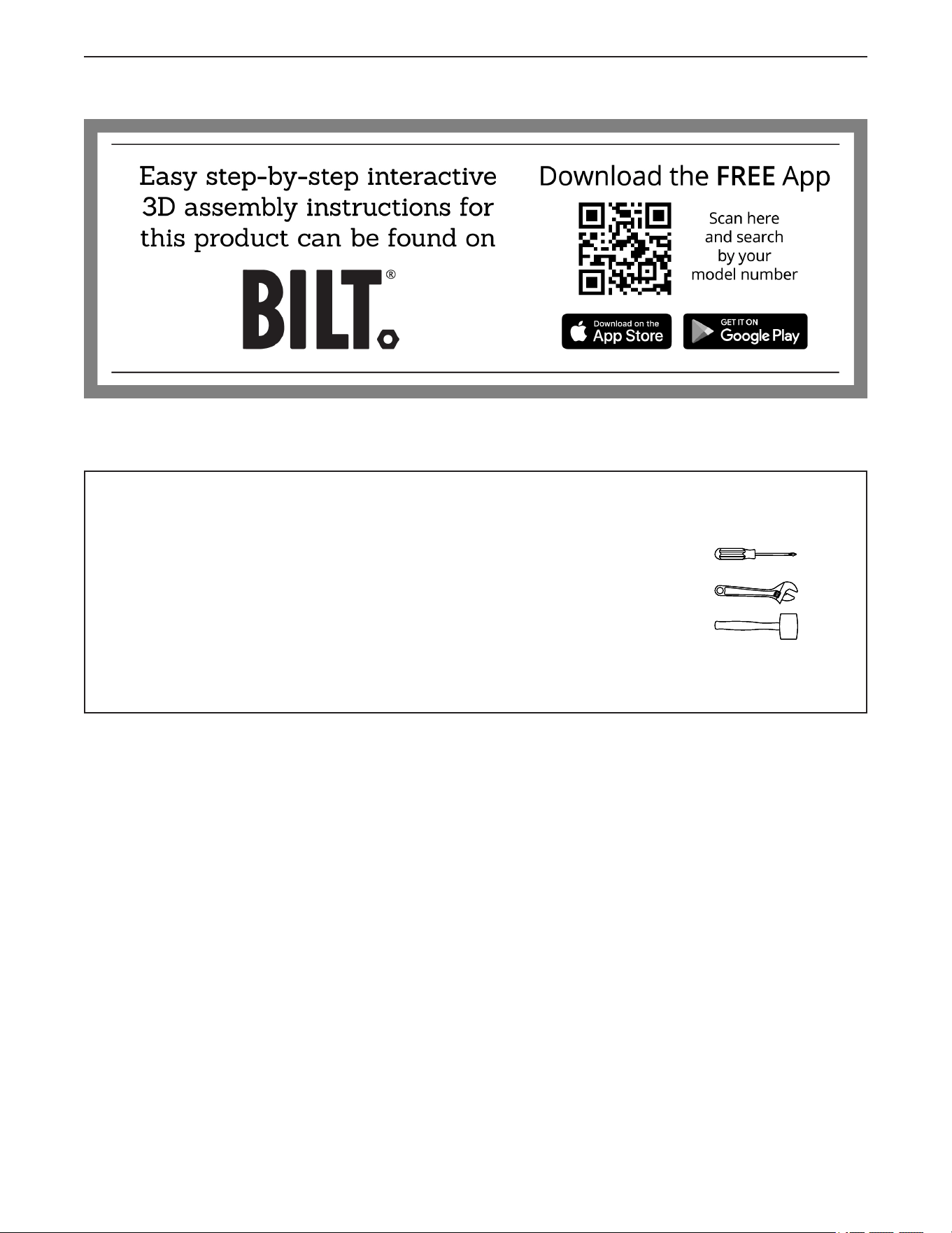
ASSEMBLY
1. To use the assembly steps in this manual, first see the helpful tips below.
• Assembly requires two persons.
• Place all parts in a cleared area and remove the
packing materials. Do not dispose of the packing
materials until you complete all assembly steps.
• To identify small parts, see page 5.
• To avoid damaging parts, do not use power tools.
• In addition to the included tool(s), assembly
requires the following tool(s):
one Phillips screwdriver
one adjustable wrench
one rubber mallet
Assembly may be easier if you have a set of
wrenches.
7
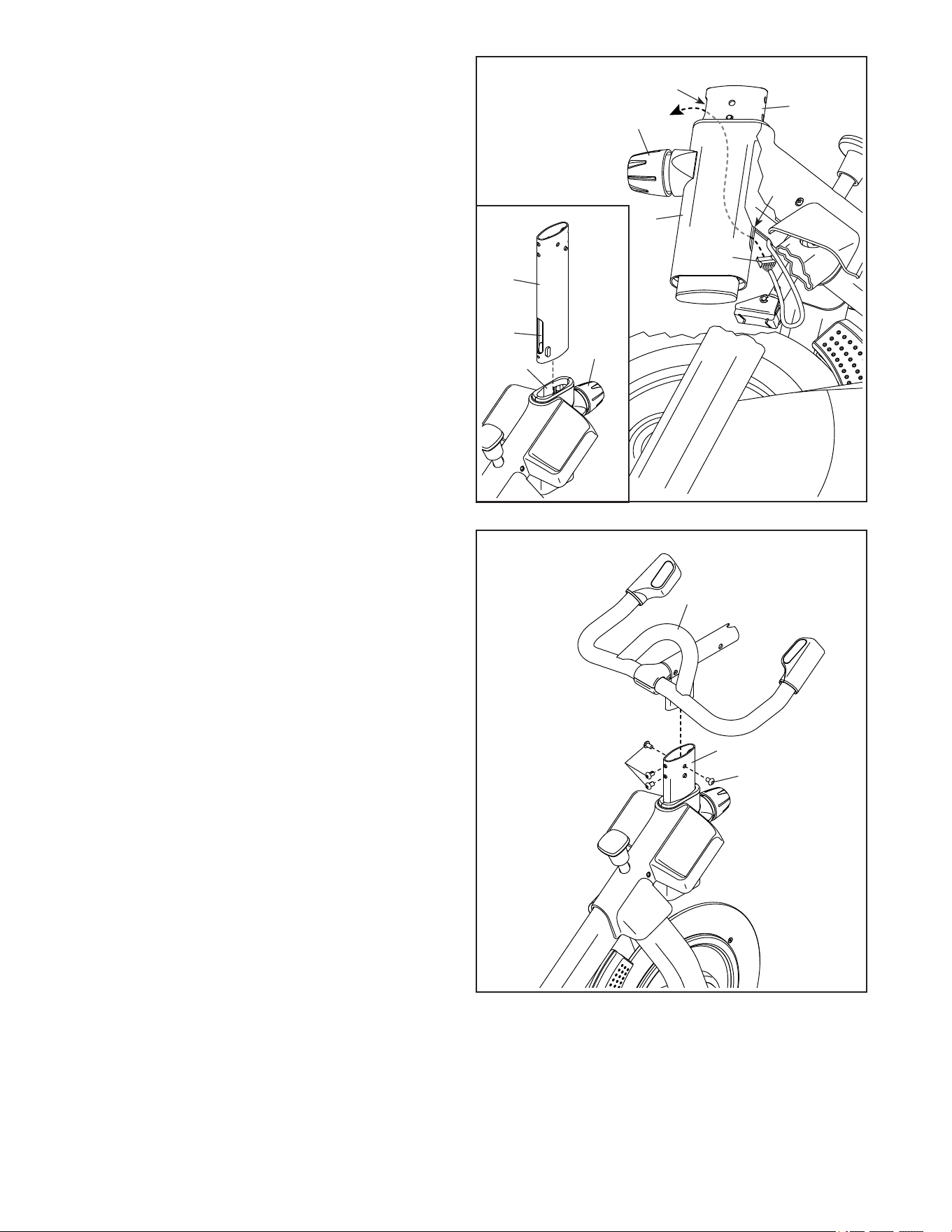
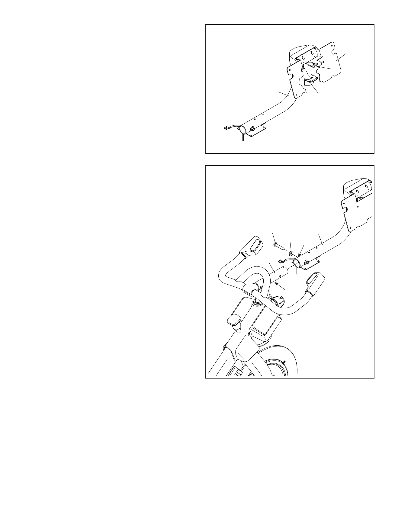
2
2. See the inset drawing. Orient the Handlebar
Post (7) so that the lower slot (A) is on the side
shown.
Next, loosen the indicated Post Knob (100) and
insert the Handlebar Post (7) into the Frame
(1) until the lower end of the Handlebar Post is
below the Frame. Make sure that the indicated
slots (B) are aligned. Then, tighten the Post
Knob.
Then, insert the end of the Lower Wire (122) into
the Frame (1) and the Handlebar Post (7) and
pull it out of the upper slot (C) in the Handlebar
Post as shown by the dashed line at the right.
100
100
122
7
A
C
B
1
7
1
3
3. Insert the Handlebar (97) into the Handlebar
Post (7). Attach the Handlebar with four
M8 x 12mm Patch Screws (93); start all the
Patch Screws, and then tighten them.
97
7
93
93
8
5. Tip: Avoid pinching the wires (D, E). Slide the
Console Support (8) onto the Handlebar (97).
Attach the Console Support (8) with an
M10 x 55mm Screw (94) and an M10 Washer
(3); do not fully tighten the Screw yet.
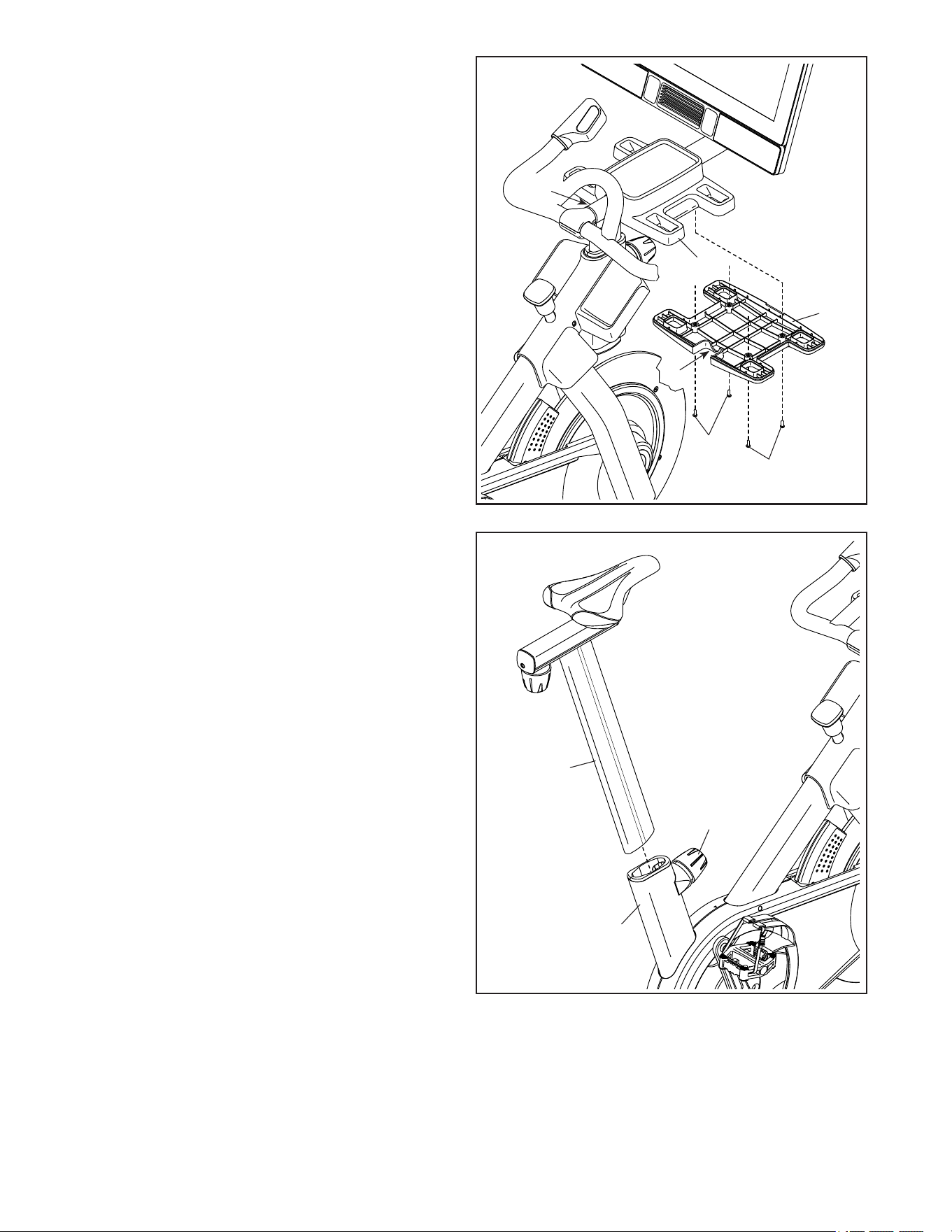
4. Remove the Mount Cover (153) from the
Console Support (8), if necessary. Then, pull
the wires (D) out of the Console Support. Make
sure that the wires are behind the Console
Bracket (11).
Then, press the Mount Cover (153) into place on
the Console Support (8).
Avoid pinching the
wires (D, E)
4
D
E
94
3
8
8
11
97
5
153
D
9
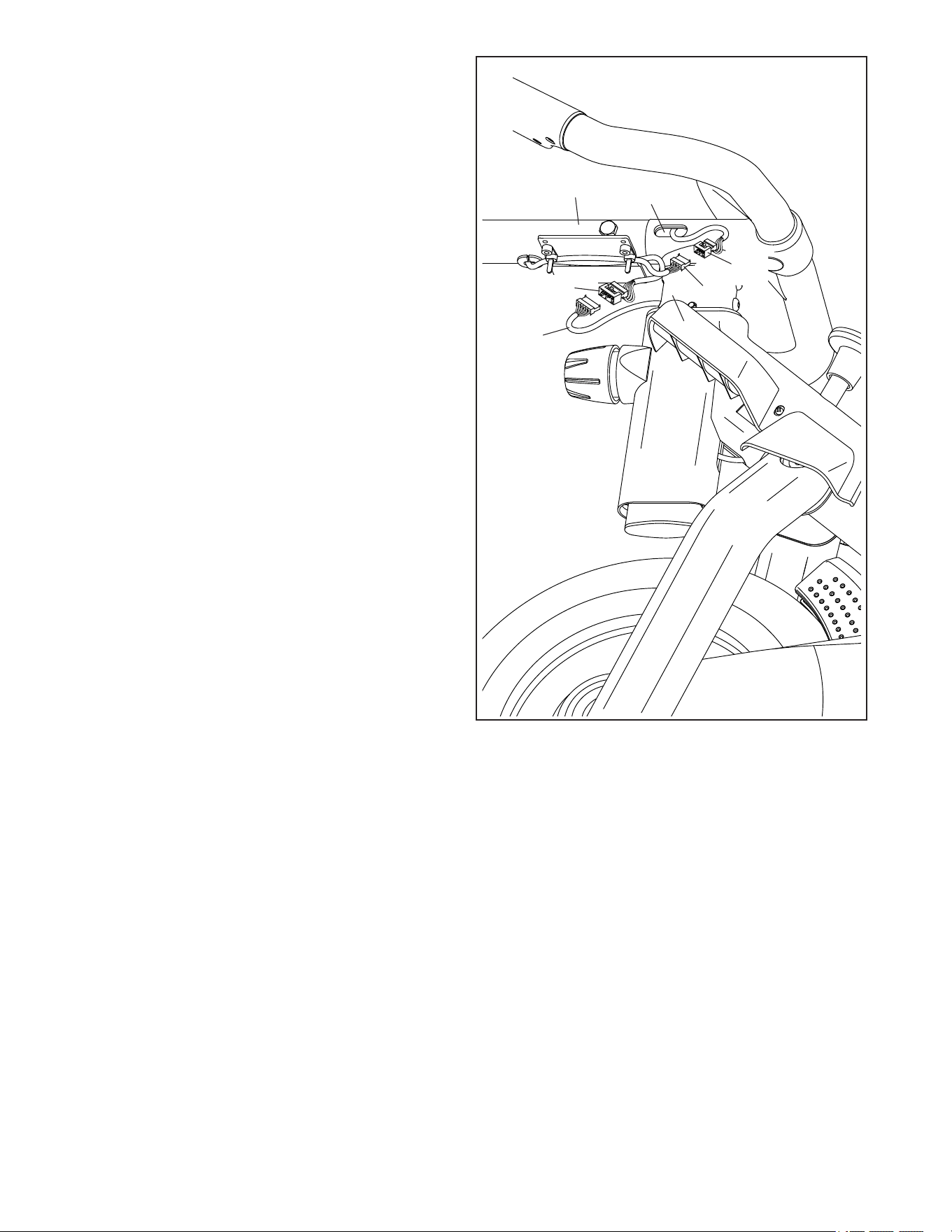
6. Look under the Console Support (8) and identify
the Upper Wire (123), which has a larger con-
nector than the Extension Wire (124).
Connect the Upper Wire (123) to the Lower
Wire (122) extending from the Handlebar Post
(7). Tip: The wire connectors should slide
together easily and snap into place with an
audible click. If they do not, turn one connec-
tor and try again.
Then, connect the Extension Wire (124) to
the Control Wire (125) extending from the
Handlebar (97) in the same way.
8
7
97
122
125
124
6
123
10
Note: This drawing is scaled to 94% compared to the
other assembly drawings and to the exploded drawing.
Note: This drawing is scaled to 94% compared to the
other assembly drawings and to the exploded drawing.
Note: This drawing is scaled to 94% compared to the
other assembly drawings and to the exploded drawing.
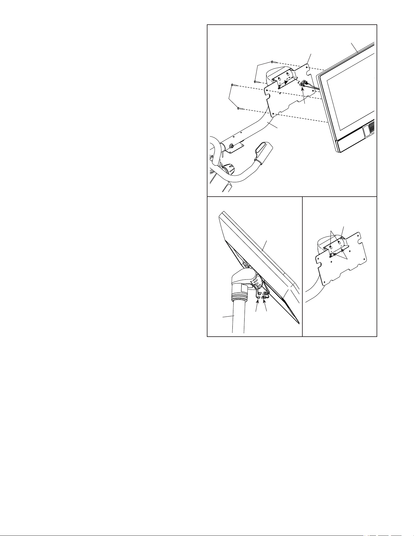
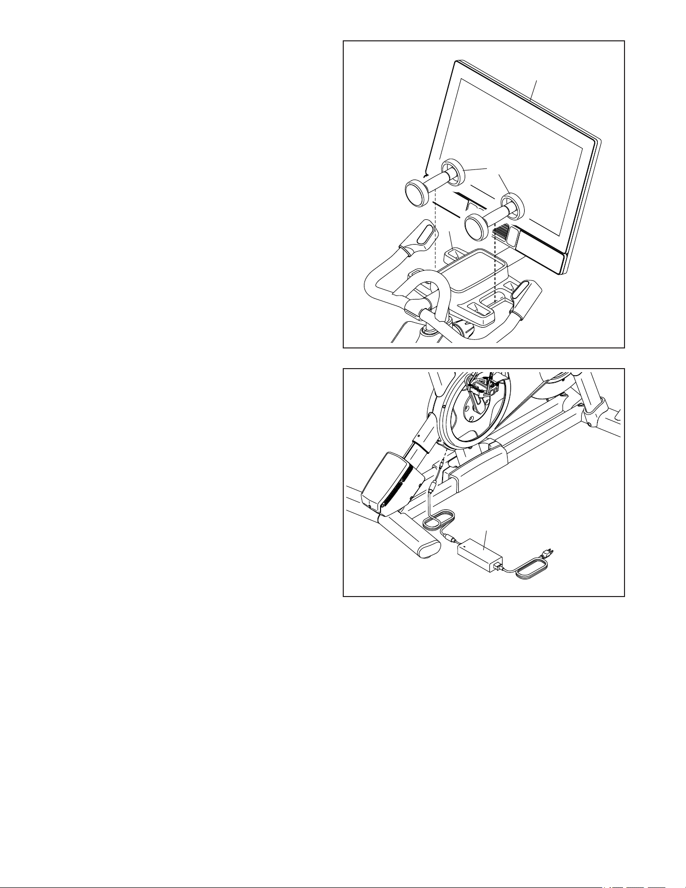
7. Have a second person hold the Console
(10) near the Console Bracket (11). Then,
route the wires (F) on the back of the
Console through the opening in the Console
Bracket as shown by the dashed line at the right.
See inset drawing a. Connect the wires (D)
from the Console Support (8) to the match-
ing wires (F) on the back of the Console (10).
Tip: The wire connectors should slide
together easily and snap into place with an
audible click. If they do not, turn one connec-
tor and try again.
Tip: Avoid pinching the wires (F, D). If
necessary, adjust the tilt of the Console
Bracket (11) to make this step easier. Attach
the Console (10) to the Console Bracket with
four M6 x 20mm Machine Screws (102); start all
the Machine Screws, and then tighten them.
Tilt the Console (10) upward and downward
a few times. If the movement feels too
loose, see inset drawing b. Tighten the four
M6 x 15mm Cap Screws (157) in the Rear
Bracket Mount (114) until the movement no
longer feels loose. Note: For clarity, the Console
and the wires are not shown. Tilt the Console
upward and downward to access the Cap
Screws.
7
a
b
11
10
102
102
8
Avoid pinching
the wires (F, D)
157
157
114
10
D
F
8
F
11
9
10
17
D, E
I
94
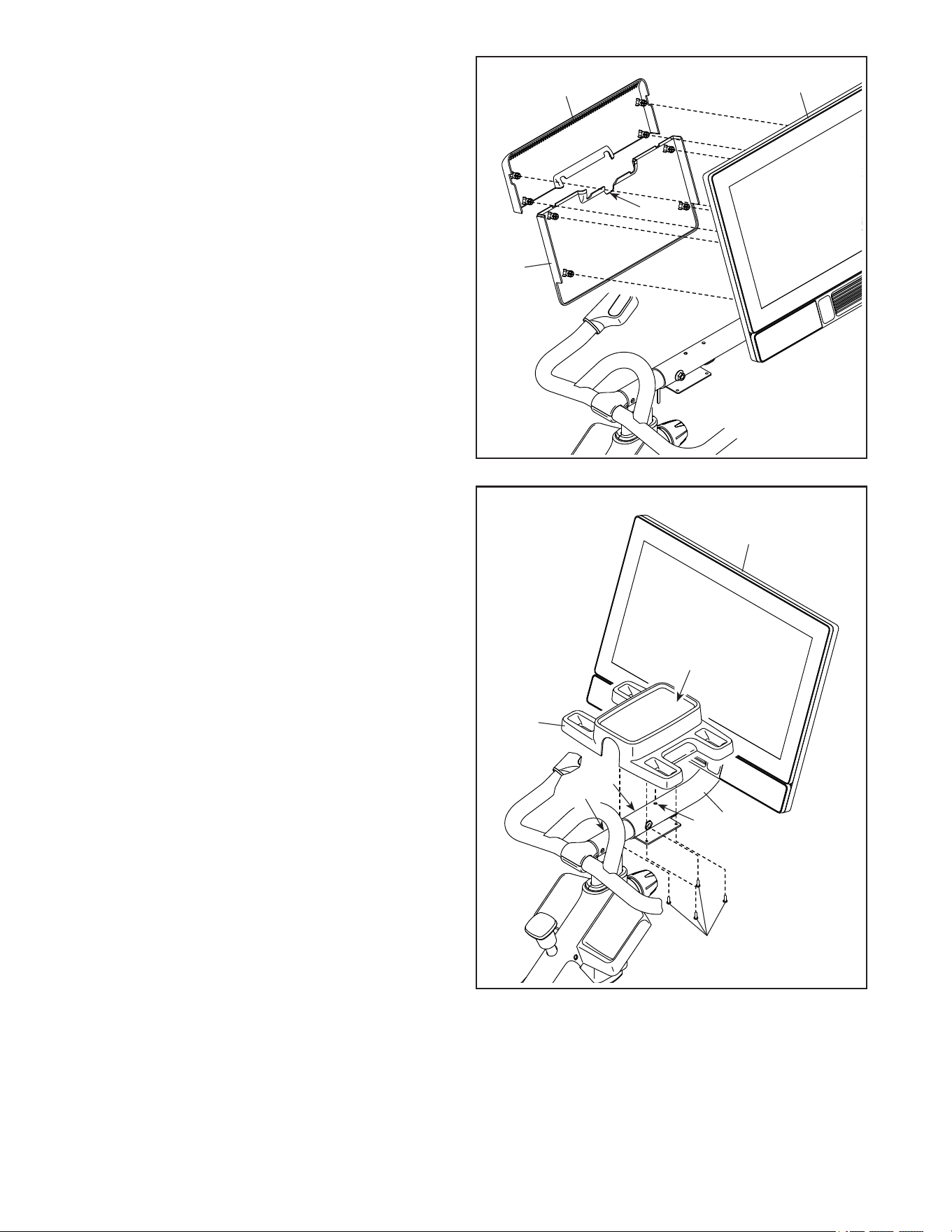
8. Orient the Lower Console Cover (154) as shown
and press it onto the back of the Console (10).
Position the wires (not shown) in the indi-
cated notch (G).
Tip: Avoid pinching the wires. Orient the
Upper Console Cover (155) as shown and press
it onto the back of the Console (10).
9. Hold the sides of the Console (10) and rotate the
Console to the position shown.
IMPORTANT: Have a second person move the
Console (10) from side to side, if necessary,
so that it is level. While the second person
holds the Console still, firmly tighten the
M10 x 55mm Screw (94).
Next, orient the Hand Weight Tray (38) so
that the orientation sticker (H) is in the loca-
tion shown. Then, set the Hand Weight Tray on
the Console Support (8), and insert the small
post (not shown) on the underside of the Hand
Weight Tray into the hole (I) in the Console
Support.
Tip: Avoid pinching the wires (D, E). Attach
the Hand Weight Tray (38) to the Console
Support (8) with four #8 x 5/8" Screws (17); start
all the Screws, and then tighten them.
Avoid
pinching
the wires
(D, E)
8
38
H
8
155
154
G
10
Avoid
pinching
the wires
12
13
1
100
10
11
10. Position the wires (D, E) so that they fit neatly in
the underside of the Hand Weight Tray (38).
Orient the Tray Cover (106) so that the curved
opening (J) is in the location shown. Then, align
the Tray Cover with the Hand Weight Tray (38).
Tip: Avoid pinching the wires (D, E). Attach
the Tray Cover (106) with four #8 x 5/8" Screws
(17); start all the Screws, and then tighten
them.
11. Orient the Saddle Post (13) as shown.
Loosen the indicated Post Knob (100). Next,
insert the Saddle Post (13) into the Frame (1),
and slide the Saddle Post to the desired height.
Then, tighten the Post Knob.
38
106
17
17
J
D, E
Avoid
pinching
the wires
(D, E)
13
14
12. Set the two Hand Weights (14) in the Hand
Weight Tray (38).
IMPORTANT: Make sure not to hit the
Console (10) with the Hand Weights (14)
when you set the Hand Weights in the Hand
Weight Tray (38) after each use.
12
38
10
14. After the studio cycle is assembled, inspect it to make sure that it is assembled correctly and that it
functions properly. Make sure that all parts are properly tightened before you use the studio cycle.
Extra parts may be included. Place a mat beneath the studio cycle to protect the floor. The use of the remain-
ing parts will be explained in HOW TO USE THE STUDIO CYCLE, beginning on page 14.
IMPORTANT: To register your product and activate your warranty in the UK, go to iconsupport.eu. If you
do not have internet access, complete the warranty registration card in the warranty booklet and send it by
registered post to the address on the back cover of the warranty booklet.
IMPORTANT: To register your product and activate your warranty in Australia, email or post the following
information to the email address or postal address on the front cover of this manual: your receipt (make sure
to keep a copy); your name, address, and telephone number; and the model number, serial number, and
name of your product (see the front cover of this manual).
119
13. IMPORTANT: Always plug the Power Adapter
(119) into the studio cycle before you plug it
into an outlet.
Plug the Power Adapter (119) into the receptacle
on the rear of the studio cycle.
Note: To plug the Power Adapter (119) into an
outlet, see HOW TO PLUG IN THE POWER
ADAPTER on page 14.
IMPORTANT: Keep the included tools in a
secure location. You will need them for future
adjustment and maintenance of your studio
cycle.
13
14
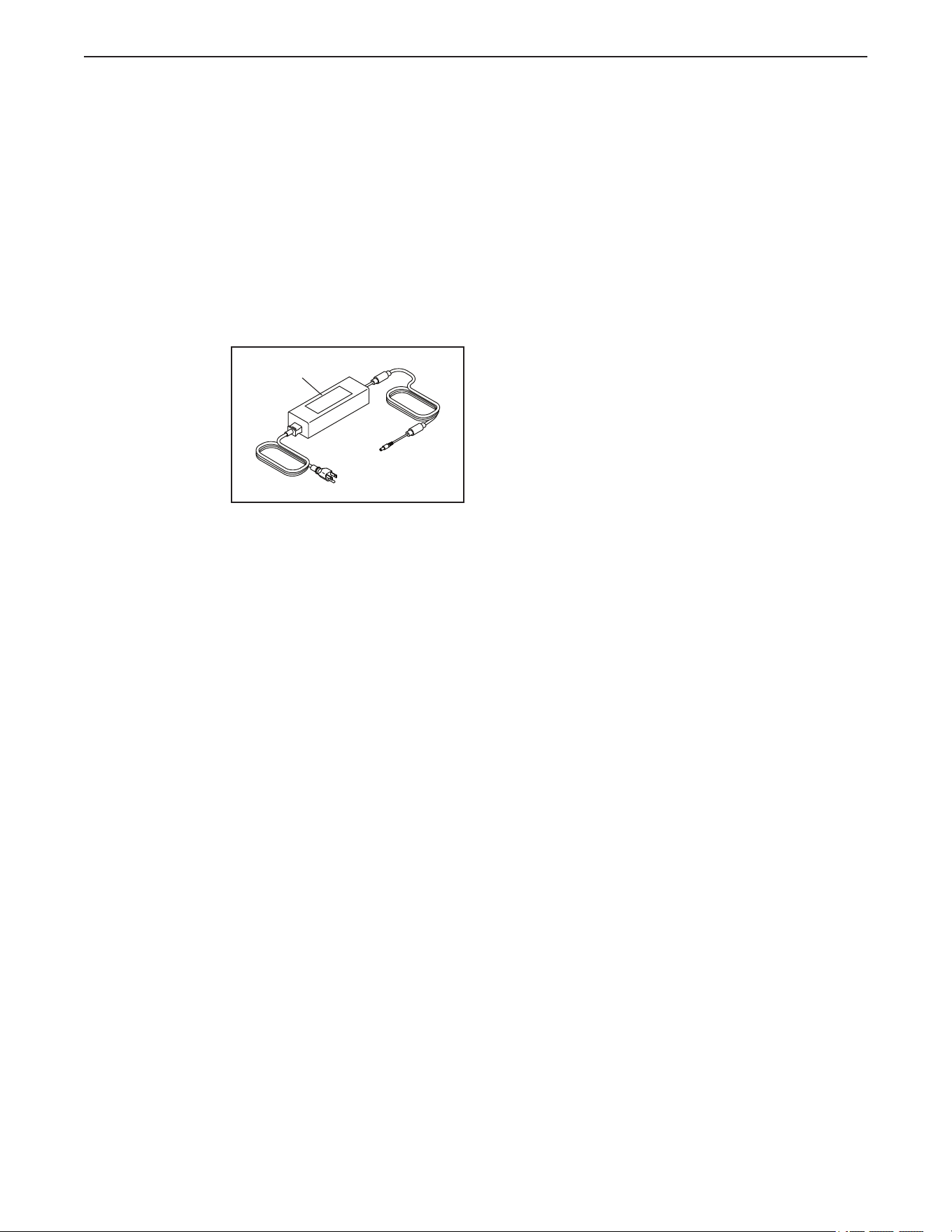
HOW TO PLUG IN THE POWER ADAPTER
IMPORTANT: If the studio cycle has been exposed
to cold temperatures, allow it to warm to room tem-
perature before you plug in the power adapter (A).
If you do not do this, you may damage the console
displays or other electronic components.
IMPORTANT: Always plug the power adapter (A)
into the studio cycle before you plug it into an
outlet.
Make sure
that the power
adapter (A) is
plugged into
the receptacle
on the studio
cycle. Then,
plug the power
adapter into an
appropriate out-
let that is properly installed in accordance with all local
codes and ordinances.
FEATURES OF THE STUDIO CYCLE
Measuring Watts
Each studio cycle is calibrated to measure your power
output and to allow you to monitor your watts and
RPMs directly on the console.
By monitoring your watts and RPMs, you can see
how hard you are training and make sure that you are
challenging yourself and improving.
The Incline System
The studio cycle can incline and decline to realistically
simulate outdoor terrain. When you use or create map
workouts of training routes with iFIT
®
(see the console
instructions beginning on page 18 for more informa-
tion), the studio cycle will automatically incline and
decline to match the real-world terrain.
Interactive Wireless Touchscreen Console
The wireless touchscreen console works with iFIT to
provide an interactive and immersive in-home studio
experience that allows you to participate virtually in
group studio classes led by personal trainers and to
experience workouts around the world.
A
HOW TO USE THE STUDIO CYCLE
15
HOW TO ADJUST THE GEOMETRY OF THE
STUDIO CYCLE
The studio cycle can be adjusted to match the geom-
etry of your road bike to promote correct form and to
ensure proper training of the muscles. Make adjust-
ments in small increments, and then pedal the
studio cycle to test the adjustments.
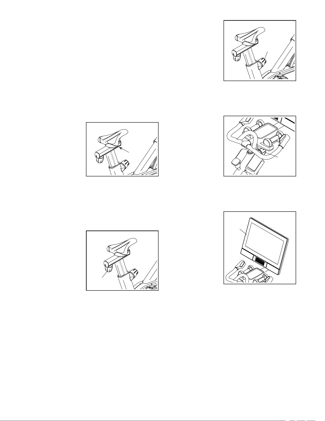
How to Adjust the Angle of the Saddle
You can adjust the angle of the saddle to the posi-
tion that is most comfortable. You can also adjust the
saddle forward or backward for increased comfort or to
adjust the distance to the handlebar.
To adjust the sad-
dle, first loosen the
saddle screw (B) in
the carriage a few
turns. Next, tilt the
saddle upward or
downward or slide
the saddle forward
or backward to the
desired position.
Then, retighten the saddle screw.
Note: You can remove the saddle and attach your
own saddle to the studio cycle if desired.
How to Adjust the Saddle Carriage
To adjust the posi-
tion of the carriage,
loosen the carriage
knob (C), move the
carriage forward
or backward to the
desired position,
and then firmly
tighten the carriage
knob.
How to Adjust the Saddle Post
For effective training, the saddle should be at the
proper height. As you pedal, there should be a slight
bend in your knees when the pedals are in the lowest
position.
To adjust the saddle
post, loosen the
post knob (D),
move the saddle
post upward or
downward, and
then firmly tighten
the post knob.
IMPORTANT: Do
not raise the sad-
dle post beyond
the “MAX” mark on the saddle post.
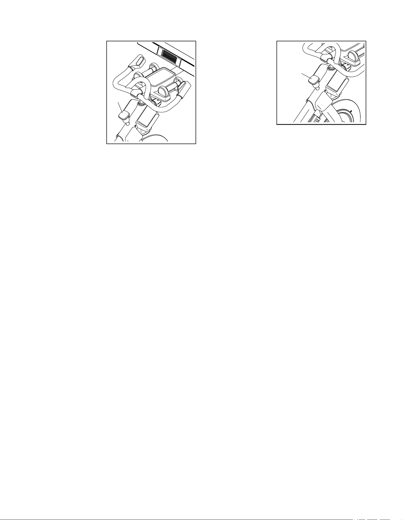
How to Adjust the Handlebar Post
To adjust the han-
dlebar post, loosen
the post knob (E),
move the handle-
bar post upward
or downward, and
then firmly tighten
the post knob.
IMPORTANT:
Do not raise the
handlebar post
beyond the “MAX” mark on the handlebar post.
How to Adjust the Position of the Console
The console (F) can
be adjusted upward,
downward, or to
the side. To adjust
the position of the
console, simply hold
the sides of the con-
sole and press it to
the desired position.
You can pivot the
console all of the
way to the side so
that you can view it
while standing next to the studio cycle to perform hand
weight exercises or other floor exercises.
If the console feels too loose or does not stay in place
when it is moved up or down or from side to side, see
HOW TO ADJUST THE CONSOLE PIVOT AND TILT
on page 31.
B
C
E
F
D
16
HOW TO LEVEL THE STUDIO CYCLE
If the studio cycle
rocks slightly on
your floor during
use, turn one or
both of the leveling
feet (G) beneath the
rear stabilizer until
the rocking motion
is eliminated.
HOW TO USE THE PEDALS
Note: You can remove the pedals and attach your
own pedals to the studio cycle if desired.
How to Use the Toe Cage Side of the Pedals
To use the toe cage
side of the pedals,
insert your shoes
into the toe cages
and pull the ends
of the toe straps.
To adjust the toe
straps, press and
hold the tabs (H) on
the buckles, adjust
the toe straps to the desired position, and then release
the tabs.
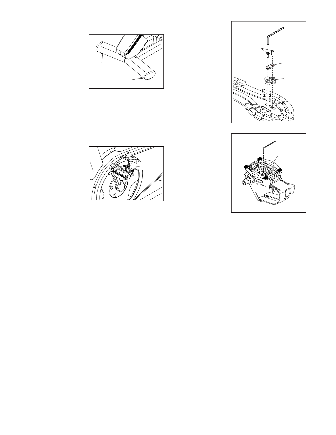
How to Attach the Cleats and Adjust the Spring
Tension of the Pedals
To use the clip-in side of the pedals, you must first
attach the included cleats to your cycling shoes (not
included).
Using the included
hex key, attach
a cleat (I) to the
bottom of a cycling
shoe with a cleat
bracket (J) and two
cleat screws (K).
Attach the other
cleat to your other
cycling shoe in the
same way.
The spring tension
affects how easy or
difficult it is to clip in
and unclip from the
pedals. To adjust
the spring tension
of a pedal (L), use
the included hex
key and tighten or
loosen the adjust-
ment screw (M) as
desired. Adjust the
spring tension of
the other pedal in
the same way.
How to Use the Clip-in Side of the Pedals
To use the clip-in side of the pedals, you must wear
cycling shoes and the included cleats must be attached
to your cycling shoes. See HOW TO ATTACH THE
CLEATS AND ADJUST THE SPRING TENSION OF
THE PEDALS at the left.
To clip into the pedals, press the cleats on your cycling
shoes firmly into the slots in the pedals until they snap
into place. To unclip from the pedals, twist the heels of
your cycling shoes outward from the pedals.
G
G
H
ProForm
NordicTrack
M
L
ProForm
NordicTrack
I
J
K
17
HOW TO USE THE BRAKE KNOB
To change the
resistance of the
pedals, press the
buttons on the right
handlebar (see step
3 on page 21). To
stop the flywheel,
push the brake
knob (N). The
flywheel will quickly
come to a complete
stop.
HOW TO LOCK THE STUDIO CYCLE
IMPORTANT: Lock
the studio cycle
when it is not in
use. To lock the
studio cycle, press
the brake knob
(N) downward and
tighten it firmly. This
will lock the studio
cycle so that the
flywheel cannot
turn. To unlock the
studio cycle, loosen
the brake knob.
N
N
18
Florida
EBNT02422
NTEX02422
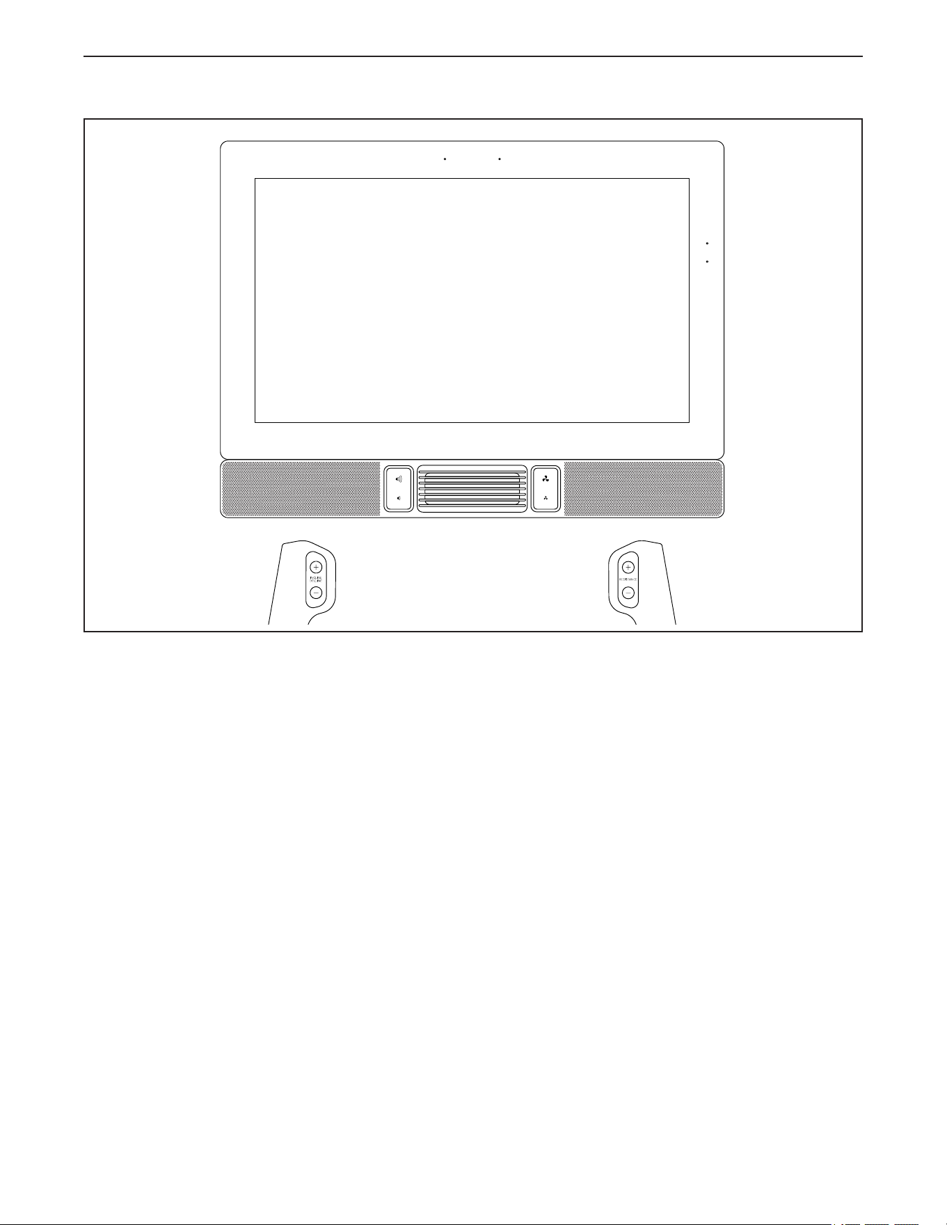
CONSOLE
DIAGRAM
HOW TO USE THE CONSOLE
FEATURES OF THE CONSOLE
The advanced console offers an array of features
designed to make your workouts more effective and
enjoyable.
The console features wireless technology that enables
the console to connect to iFIT. With iFIT, you can
access a large and varied workout library, create your
own workouts, track your workout results, and access
many other features.
In addition, the console offers a selection of featured
workouts. Each workout automatically controls the
resistance of the pedals and the incline of the frame as
it guides you through an effective exercise session.
When you use the manual mode of the console, you
can change the resistance of the pedals and the incline
of the frame with the touch of a button.
While you exercise, the console will display continuous
exercise feedback. You can even measure your heart
rate using a compatible heart rate monitor.
To turn on and turn off the console, see page 19.
To learn how to use the touch screen, see
page 19. To set up the console, see page 20.

19
HOW TO TURN ON THE CONSOLE
The included power adapter must be used to operate
the studio cycle. See HOW TO PLUG IN THE POWER
ADAPTER on page 14.
When the power adapter is
plugged in, press the power
switch (A) located on the frame
of the studio cycle to turn on the
console. It will take a moment for
the console to be ready for use.
If the console is inactive, simply touch the screen
to activate the console.
Note: When you turn on the console for the rst
time, the incline system may calibrate automati-
cally. The frame will move upward and downward as
it calibrates. When the frame stops moving, the incline
system is calibrated.
IMPORTANT: If the incline system does not
calibrate automatically, see step 5 on page 20
and manually calibrate the incline system.
HOW TO TURN OFF THE CONSOLE
If the pedals do not move for several seconds, the
console will pause.
If the pedals do not move for several minutes, the
screen is not touched, and the buttons are not pressed,
the console will become inactive.
When you are finished exercising, press the power
switch and unplug the power adapter. IMPORTANT: If
you do not do this, the electrical components on
the studio cycle may wear prematurely.
HOW TO USE THE TOUCH SCREEN
The console features a tablet with a full-color touch
screen. The following information will help you use the
touch screen:
• The console functions similarly to other tablets. You
can slide or flick your finger against the screen to
move certain images on the screen, such as the
displays in a workout.
• To type information into a text box, first touch the text
box to view the keyboard. To use numbers or other
characters on the keyboard, touch ?123. To view
more characters, touch ~[<. Touch ?123 again to
return to the number keyboard. To return to the letter
keyboard, touch ABC. To use a capital character,
touch the shift button (upward-facing arrow symbol).
To use multiple capital characters, touch the shift
button again. To return to the lowercase keyboard,
touch the shift button a third time. To clear the last
character, touch the clear button (backward-facing
arrow with an X symbol).
A

20
HOW TO SET UP THE CONSOLE
Before you use the studio cycle for the first time, set up
the console.
1. Connect to your wireless network.
To use iFIT workouts and to use several other
features of the console, the console must be con-
nected to a wireless network. Follow the prompts
on the screen to connect the console to your wire-
less network.
2. Customize settings.
Follow the prompts on the screen to set the desired
unit of measurement and your time zone.
Note: To change these settings later, see HOW TO
CHANGE CONSOLE SETTINGS on page 27.
3. Log into or create an iFIT account.
Follow the prompts on the screen to log into your
iFIT account or to create an iFIT account.
4. Check for firmware updates.
First, touch the menu button (three horizontal lines
symbol), touch Settings, touch Maintenance, and
then touch Update. The console will check for firm-
ware updates. For more information, see HOW TO
CHANGE CONSOLE SETTINGS on page 27.
Firmware updates are always designed to
improve your exercise experience. As a result,
new settings and features may not be described
in this manual. Take time to explore the console
to learn how new settings and features work.
Also, some settings and features described in this
manual may no longer be enabled.
5. Calibrate the incline system.
First, touch the menu button (three horizontal lines
symbol), touch Settings, touch Maintenance, and
then touch Calibrate Incline. The frame will rise
and lower as it calibrates. For more information,
see HOW TO CHANGE CONSOLE SETTINGS on
page 27.
The console is now ready for you to begin working out.
The following pages explain the workouts and other
features that the console offers.
To use the manual mode, see page 21. To use a
featured workout, see page 23. To create a draw-
your-own-map workout, see page 25. To use an
iFIT workout, see page 26.
To change console settings, see page 27. To
connect to a wireless network, see page 29.
Note: If there is a sheet of plastic on the screen,
remove the plastic.

21
HOW TO USE THE MANUAL MODE
1. Touch the screen or press any button on the
console to turn on the console.
See HOW TO TURN ON THE CONSOLE on
page 19. Note: It may take a few moments for
the console to be ready for use.
2. Select the home screen.
When you turn on the console, the home screen
will appear on the screen after the console
boots up.
If you are in a workout, touch the screen and fol-
low the prompts to end the workout and return to
the home screen. If you are in the settings menus,
touch the back button (arrow symbol) to return to
the home screen.
3. Change the resistance of the pedals and the
incline of the frame as desired.
Touch Manual Start and begin pedaling.
You can change the resistance of the pedals by
pressing the Resistance increase and decrease
buttons on the right handlebar or by touching the
resistance sliders on the screen.
You can change the incline of the frame by
pressing the Incline/Decline increase and decrease
buttons on the left handlebar or by touching the
incline sliders on the screen.
Note: After you press a button, it will take a
moment for the pedals to reach the selected
resistance level or for the frame to reach the
selected incline level. When the studio cycle is
declined or extremely inclined, the range of
resistance levels may decrease.
Note: To view the resistance or incline sliders on
the screen, touch the screen in any open space
and then touch the controls options to enable this
feature.
4. Follow your progress.
The console offers several display modes. The
display mode that you select will determine which
workout information is shown.
Drag upward on the screen to enter the fullscreen
display mode. Drag downward on the screen to
view the workout information displays.
Touch the various workout information displays
to view more options. Touch the more button
(+ symbol) to view statistics or charts. Touch the
center of the screen to view even more display
mode options.
If desired, adjust the volume level by
pressing the volume increase and
decrease buttons.
To pause the workout, touch the screen and touch
the pause option or simply stop pedaling. To con-
tinue the workout, touch the start option or simply
resume pedaling.
To end the workout session, touch the screen,
touch the pause option, and then follow the
prompts on the screen to end the workout and
return to the home screen.

22
5. Wear a compatible heart rate monitor and
measure your heart rate if desired.
You can wear a compatible heart rate monitor (not
included) to measure your heart rate. The console
is compatible with all Bluetooth
®
Smart heart rate
monitors.
A compatible heart rate monitor is included with
some models. If a heart rate monitor is included,
see THE HEART RATE MONITOR in this manual
to learn how to use it.
If this model does not include a compatible
heart rate monitor, see this page for information
about ordering one.
The console will connect to your compatible heart
rate monitor automatically. When your heartbeat is
detected, your heart rate will be shown.
6. Turn on the fan if desired.
The fan has several speed settings,
including an auto mode. While the
auto mode is selected, the speed of
the fan will automatically increase
or decrease as your pedaling speed
increases or decreases. Press the
fan increase and decrease buttons repeatedly to
select a fan speed or to turn off the fan.
Note: If the pedals are not moved for a while when
the home screen is selected, the fan will turn off
automatically.
7. When you are finished exercising, turn off the
console.
See HOW TO TURN OFF THE CONSOLE on
page 19.
THE OPTIONAL HEART RATE MONITOR
Whether your
goal is to
burn fat or to
strengthen your
cardiovascular
system, the key
to achieving the
best results is
to maintain the
proper heart
rate during your
workouts. The optional heart rate monitor will enable
you to continuously monitor your heart rate while you
exercise, helping you to reach your personal fitness
goals. To purchase an optional heart rate monitor,
please see the front cover of this manual.
Note: The console is compatible with all Bluetooth
Smart heart rate monitors.

23
HOW TO USE A FEATURED WORKOUT
To use a featured workout, the console must be con-
nected to a wireless network (see HOW TO CONNECT
TO A WIRELESS NETWORK on page 29).
1. Touch the screen or press any button on the
console to turn on the console.
See HOW TO TURN ON THE CONSOLE on
page 19. Note: It may take a few moments for
the console to be ready for use.
2. Select the home screen or the workout library.
When you turn on the console, the home screen
will appear on the screen after the console
boots up.
If you are in a workout, touch the screen and fol-
low the prompts to end the workout and return to
the home screen. If you are in the settings menus,
touch the back button (arrow symbol) to return to
the home screen.
Touch the buttons at the bottom of the screen to
select either the home screen (Home button) or the
workout library (Browse button).
3. Select a workout.
To select a workout from the home screen or the
workout library, simply touch the desired workout
button on the screen. Slide or flick the screen to
scroll upward or downward if necessary.
The featured workouts on your console will change
periodically. To save one of the featured workouts
for future use, you can add it as a favorite by touch-
ing the favorites button (heart symbol). You must
be logged into your iFIT account to save a featured
workout (see step 3 on page 26).
To draw your own map for a workout, see HOW TO
CREATE A DRAW-YOUR-OWN-MAP WORKOUT
on page 25.
When you select a workout, the screen will show
an overview of the workout that includes details
such as the duration and distance of the workout
and the approximate number of calories you will
burn during the workout.
4. Start the workout.
Touch Start Workout to start the workout.
During some workouts, an iFIT coach will guide
you through an immersive video workout. Touch
the screen in any open space to view and select
music, trainer voice, and volume options for the
workout.
During some workouts, the screen will show a map
of the route and a marker indicating your prog-
ress. Touch the buttons on the screen to select the
desired map options.
During some workouts, you may be prompted to
maintain a target speed. As you exercise, keep
your pedaling speed near the target speed.
IMPORTANT: The target speed is intended only
to provide motivation. Your actual pedaling
speed may be slower than the target speed.
Make sure to pedal at a speed that is comfort-
able for you.
If the resistance level and/or incline level is too
high or too low, you can manually override the
setting by pressing the Resistance buttons or the
Incline/Decline buttons (see step 3 on page 21).
To return to the programmed resistance
and/or incline settings of the workout, touch
Follow Trainer.
If the smart adjust feature is enabled, the con-
sole will scale the intensity level of the workout
automatically based on your manual overrides of
the resistance and incline settings. To enable the
smart adjust feature, touch the screen in any open
space and then touch the smart adjust toggle.

24
IMPORTANT: The calorie goal shown in the
workout description is an estimate of the
number of calories that you will burn during
the workout. The actual number of calories
that you burn will depend on various factors,
such as your weight. In addition, if you manu-
ally change the resistance level or incline level
of the frame during the workout, the number of
calories you burn will be affected.
If the active pulse feature is enabled, the con-
sole will scale the intensity level of the workout
automatically based on your heart rate when you
wear a compatible heart rate monitor (see step 6).
To enable the active pulse feature, see HOW TO
CHANGE CONSOLE SETTINGS on page 27.
To follow your progress with the display modes,
see step 4 on page 21.
To pause the workout, touch the screen and touch
the pause option or simply stop pedaling. To con-
tinue the workout, touch the start option or simply
resume pedaling.
To end the workout session, touch the screen,
touch the pause option, and then follow the
prompts on the screen to end the workout and
return to the home screen.
When the workout ends, a workout summary will
appear on the screen. If desired, you can select
options such as adding the workout to your sched-
ule (see HOW TO USE AN IFIT WORKOUT on
page 26) or adding the workout to your favor-
ites list. Then, touch Finish to return to the home
screen.
5. Wear headphones if desired.
To connect your headphones to the console, first
turn on your headphones, place them in pairing
mode, and place them near the console. Then,
touch the screen in any open space, touch the
option to connect your headphones, and select
your headphones from the list on the screen.
When your headphones and the console pair
successfully, the audio from the console will play
through your headphones.
6. Wear a compatible heart rate monitor and
measure your heart rate if desired.
See step 5 on page 22.
7. Turn on the fan if desired.
See step 6 on page 22.
8. When you are finished exercising, turn off the
console.
See HOW TO TURN OFF THE CONSOLE on
page 19.

25
HOW TO CREATE A DRAW-YOUR-OWN-MAP
WORKOUT
1. Touch the screen or press any button on the
console to turn on the console.
See HOW TO TURN ON THE CONSOLE on
page 19. Note: It may take a few moments for
the console to be ready for use.
2. Select a draw-your-own-map workout.
When you turn on the console, the home screen
will appear on the screen after the console
boots up.
If you are in a workout, touch the screen and fol-
low the prompts to end the workout and return to
the home screen. If you are in the settings menus,
touch the back button (arrow symbol) to return to
the home screen.
To select a draw-your-own-map workout, touch the
Create button at the bottom of the screen.
3. Draw your map.
Navigate to the area on the map where you want
to draw your workout by typing in the search box
or by sliding your fingers on the screen. Touch
the screen to add the start point for your workout.
Then, touch the screen to add the end point for
your workout.
If you want to start and end your workout at the
same point, touch Close Loop or Out & Back in the
map options. You can also select whether you want
your workout to snap to the road.
If you make a mistake, touch Undo in the map
options.
The screen will display the elevation and distance
statistics for your workout.
4. Save your workout.
Touch the options on the screen to save your
workout. If desired, enter a title and description for
your workout.
5. Start the workout.
Touch Start Workout to start the workout. The
workout will function in the same way as a featured
workout (see page 23).
6. Wear a compatible heart rate monitor and
measure your heart rate if desired.
See step 5 on page 22.
7. Turn on the fan if desired.
See step 6 on page 22.
8. When you are finished exercising, turn off the
console.
See HOW TO TURN OFF THE CONSOLE on
page 19.

26
HOW TO USE AN IFIT WORKOUT
To use an iFIT workout, you must be logged into your
iFIT account (see step 3 below) and the console
must be connected to a wireless network (see HOW
TO CONNECT TO A WIRELESS NETWORK on
page 29).
1. Touch the screen or press any button on the
console to turn on the console.
See HOW TO TURN ON THE CONSOLE on
page 19. Note: It may take a few moments for
the console to be ready for use.
2. Select the home screen.
When you turn on the console, the home screen
will appear on the screen after the console
boots up.
If you are in a workout, touch the screen and fol-
low the prompts to end the workout and return to
the home screen. If you are in the settings menus,
touch the back button (arrow symbol) to return to
the home screen.
3. Log in to your iFIT account.
If you have not already done so, touch the menu
button (three horizontal lines symbol) on the screen
and then touch Log in to log in to your iFIT account.
Follow the prompts on the screen to enter your
username and password.
To switch users within your iFIT account, touch
the menu button, touch Settings, and then touch
Manage Accounts. If more than one user is associ-
ated with the account, a list of users will appear.
Touch the name of the desired user.
4. Select an iFIT workout from the home screen or
the workout library.
Touch the buttons at the bottom of the screen to
select either the home screen (Home button) or the
workout library (Browse button).
To select an iFIT workout from the home screen or
the workout library, simply touch the desired work-
out button on the screen. Slide or flick the screen to
scroll upward or downward if necessary.
The featured iFIT workouts shown on the home
screen will change periodically.
The workout library contains all of the iFIT work-
outs available for the studio cycle, organized into
categories. To search the workout library, touch
the search button (magnifying glass symbol), and
select the desired filtering options.
When you select an iFIT workout, the screen will
show an overview of the workout that includes
details such as the duration of the workout and
the approximate number of calories you will burn
during the workout.
You can also select options such as adding the
workout to your schedule (see step 5) or marking
the workout as a favorite (see step 6).
5. Schedule an iFIT workout on the calendar if
desired.
If desired, you can schedule an iFIT workout for
a future date. Simply view the overview or work-
out summary of the desired iFIT workout, touch
Schedule, and then select the desired date on the
calendar.
When the selected date arrives, the iFIT work-
out that you scheduled will appear on the home
screen.

27
6. Create a list of favorite iFIT workouts if desired.
To mark an iFIT workout as a favorite, simply view
the overview or workout summary of the desired
iFIT workout and touch the favorites button (heart
symbol).
To view a list of iFIT workouts that you have
marked as your favorites, select the workout library
(Browse button), and then touch My List.
7. Start the workout.
Touch Start Workout to start the workout. The
workout will function in the same way as a featured
workout (see page 23).
8. Wear headphones if desired.
To connect your headphones to the console, first
turn on your headphones, place them in pairing
mode, and place them near the console. Then,
touch the screen in any open space, touch the
option to connect your headphones, and select
your headphones from the list on the screen.
When your headphones and the console pair
successfully, the audio from the console will play
through your headphones.
9. Wear a compatible heart rate monitor and
measure your heart rate if desired.
See step 5 on page 22.
10. Turn on the fan if desired.
See step 6 on page 22.
11. When you are finished exercising, turn off the
console.
See HOW TO TURN OFF THE CONSOLE on
page 19.
For more information about iFIT, go to iFIT.com.
HOW TO CHANGE CONSOLE SETTINGS
IMPORTANT: Firmware updates are always
designed to improve your exercise experience. As a
result, new settings and features may not be described
in this manual. Take time to explore the console to
learn how new settings and features work. Also, some
settings and features described in this manual may no
longer be enabled.
1. Select the settings main menu.
First, turn on the console (see HOW TO TURN ON
THE CONSOLE on page 19). Note: It may take
a few moments for the console to be ready for use.
Next, select the home screen (Home button).
When you turn on the console, the home screen
will appear on the screen after the console boots
up. If you are in a workout, touch the screen and
follow the prompts to end the workout and return to
the home screen. If you are in the settings menus,
touch the back button (arrow symbol) to return to
the home screen.
Then, touch the menu button (three horizontal lines
symbol) on the screen, and then touch Settings.
The settings menu will appear on the screen.
2. Navigate the settings menus and change
settings as desired.
Slide or flick the screen to scroll upward or down-
ward if necessary. To view a settings menu, simply
touch the menu name. To exit a menu, touch the
back button (arrow symbol). You may be able to
view and change settings in the following settings
menus:
Account
• MyProle
• In Workout
• Manage Accounts
Equipment
• Equipment Info
• Equipment Settings
• Maintenance
• Wi-Fi
About
• Legal

28
3. Customize workout settings.
To customize workout settings and enable workout
features, touch In Workout, and then touch the
desired settings.
When the active pulse feature is enabled, the
console will scale the intensity level of workouts
based on your heart rate when you wear a compat-
ible heart rate monitor. To enable the active pulse
feature, touch the active pulse toggle. Then, select
your resting and maximum heart rates and adjust
related settings as desired.
4. Customize the unit of measurement and other
settings.
To customize the unit of measurement, the time
zone, or other settings, touch Equipment Info or
Equipment Settings, and then touch the desired
settings.
The console can display speed and distance in
either standard or metric units of measurement.
5. View machine information or console app
information.
Touch Equipment Info, and then touch Machine
Info or App Info to view information about your
studio cycle or about the console app.
6. Update the console firmware.
For the best results, regularly check for
firmware updates. Touch Maintenance, and then
touch Update to check for firmware updates using
your wireless network. The update will begin auto-
matically. IMPORTANT: To avoid damaging the
studio cycle, do not turn off the console while
the firmware is being updated.
The screen will show the progress of the update.
When the update is complete, the console will
turn off and then turn back on. If it does not, press
the power switch and unplug the power adapter,
wait for several seconds, and then plug the power
adapter in again and press the power switch.
Note: It may take a few minutes for the console to
be ready for use.
Note: Occasionally, a firmware update may cause
the console to function slightly differently. These
updates are always designed to improve your
exercise experience.
7. Calibrate the incline system.
To calibrate the incline system, touch Maintenance,
touch Calibrate Incline, and then touch Begin. The
frame will automatically rise to the maximum incline
level, lower to the minimum incline level, and then
return to the starting position. This will calibrate
the incline system. When the incline system is
calibrated, touch Finish.
IMPORTANT: Keep pets, feet, and other objects
away from the studio cycle while the incline
system is calibrating.
8. Exit the settings main menu.
If you are in a settings menu, touch the back button
to exit the settings main menu.

29
HOW TO CONNECT TO A WIRELESS NETWORK
To use iFIT workouts and to use several other features
of the console, the console must be connected to a
wireless network.
1. Select the home screen.
First, turn on the console (see HOW TO TURN ON
THE CONSOLE on page 19). Note: It may take
a few moments for the console to be ready for use.
Next, select the home screen (Home button).
When you turn on the console, the home screen
will appear on the screen after the console boots
up. If you are in a workout, touch the screen and
follow the prompts to end the workout and return to
the home screen. If you are in the settings menus,
touch the back button (arrow symbol) and then
touch the close button (x symbol) to return to the
home screen.
2. Select the wireless network menu.
Touch the menu button (three horizontal lines
symbol), and then touch Wi-Fi to select the wire-
less network menu.
3. Enable Wi-Fi.
Make sure that Wi-Fi
®
is enabled. If it is not
enabled, touch the Wi-Fi toggle to enable it.
4. Set up and manage a wireless network
connection.
When Wi-Fi is enabled, the screen will show a
list of available networks. Note: It may take a few
moments for the list of wireless networks to appear.
Note: You must have your own wireless network
and an 802.11b/g/n router with SSID broadcast
enabled (hidden networks are not supported).
When a list of networks appears, touch the desired
network. Note: You will need to know your network
name (SSID). If your network has a password, you
will also need to know the password.
Follow the prompts on the screen to enter your
password and connect to the selected wireless
network. (To use the keyboard, see HOW TO USE
THE TOUCH SCREEN on page 19.)
When the console is connected to your wireless
network, a confirmation message will appear on the
screen.
If you are having problems connecting to an
encrypted network, make sure that your password
is correct. Note: Passwords are case-sensitive.
Note: The console supports unsecured and
secured (WEP, WPA™, and WPA2™) encryption.
A broadband connection is recommended; perfor-
mance depends on connection speed.
Note: If you have questions after following
these instructions, go to support.iFIT.com for
assistance.
5. Exit the wireless network menu.
To exit the wireless network menu, touch the back
button (arrow symbol).

30
MAINTENANCE
Regular maintenance is important for optimal
performance and to reduce wear. Inspect and properly
tighten all parts each time the studio cycle is used.
Replace any worn parts immediately. Use only
manufacturer-supplied parts.
To clean the studio cycle, use a damp cloth and a small
amount of mild soap. IMPORTANT: To avoid damage
to the console, keep liquids away from the console
and keep the console out of direct sunlight.
PEDAL MAINTENANCE
Tighten the pedals weekly using the included studio
cycle tool. Tighten the right pedal clockwise, and
tighten the left pedal counterclockwise.
CONSOLE TROUBLESHOOTING
If the console does not turn on, make sure that the
power adapter is fully plugged in and that the power
switch is pressed on.
If a replacement power adapter is needed, see the
back cover of this manual. IMPORTANT: To avoid
damaging the console, use only a manufacturer-
supplied regulated power adapter.
If you are having problems connecting the console
to a wireless network or if you are having problems
with your iFIT account or iFIT workouts, go to
support.iFIT.com.
If the console does not boot
up properly, or if the con-
sole freezes and does not
respond, reset the console
to the factory default set-
tings. IMPORTANT: Doing
this will erase all custom settings you have made
to the console. Resetting the console requires two
people. First, press the power switch and unplug the
power adapter. Next, locate the small reset opening (A)
on the side or the back of the console. Using a bent
paper clip, press and hold the reset button inside the
opening, and have a second person plug in the power
adapter and press the power switch. Continue holding
the reset button until the console turns on. When the
reset operation is complete, the console will turn off
and then turn back on. If it does not, press the power
switch and unplug the power adapter, and then plug it
in again and press the power switch. Once the con-
soleturnson,checkforrmwareupdates(seeHOW
TO CHANGE CONSOLE SETTINGS on page 27).
Note: It may take a few minutes for the console to be
ready for use.
A
MAINTENANCE AND TROUBLESHOOTING
31
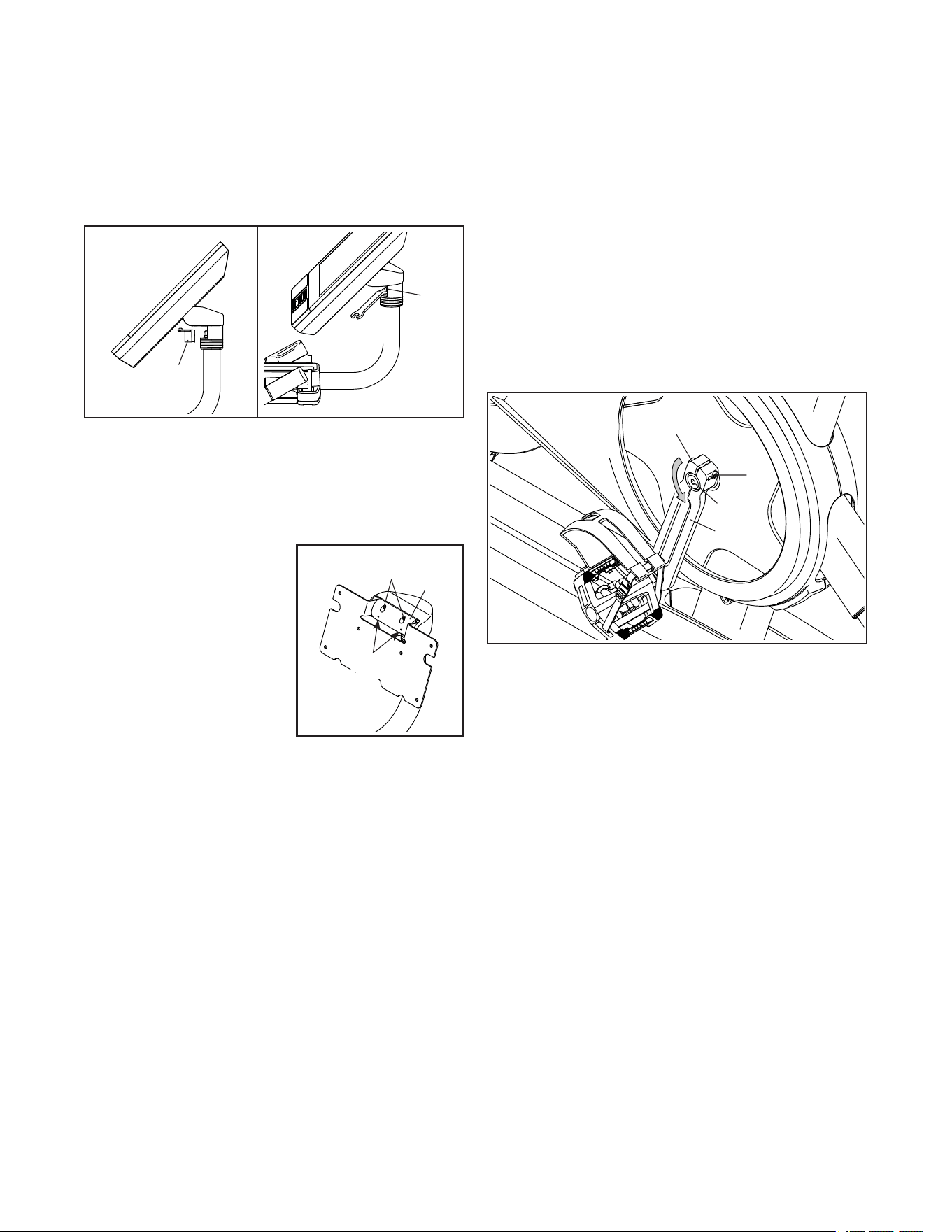
HOW TO ADJUST THE CONSOLE PIVOT AND TILT
If the console feels too loose or does not stay in place
when it is moved from side to side, first remove the
Mount Cover (153). Next, use the included studio cycle
tool to tighten the M25 Locknut (152) slightly until the
console stays in place when moved from side to side.
Then, press the Mount Cover back into place.
If the console feels too loose or does not stay in
place when it is tilted upward and downward, first
see assembly step 8 on page 11. Use a standard
screwdriver to pry off the Console Covers (154, 155).
Next, tighten the four
M6 x 15mm Cap Screws
(157) in the Rear Bracket
Mount (114) until the up
and down movement
no longer feels loose.
Note: For clarity, the con-
sole is not shown in the
drawing. Tilt the console
upward and downward to
access the Cap Screws.
Then, see assembly step 8 on page 11 and reattach
the Console Covers (154, 155).
INCLINE SYSTEM TROUBLESHOOTING
If the frame does not move to the correct incline level,
see HOW TO CHANGE CONSOLE SETTINGS on
page 27 and calibrate the incline system.
Note: When the studio cycle is declined or extremely
inclined, the range of resistance levels may decrease.
HOW TO ADJUST THE LEFT CRANK ARM
If the Left Crank Arm (21) feels loose while you are
pedaling, first loosen the two M6 x 25mm Screws (96).
Then, follow the steps below. Note: If you have a
torque wrench, tighten the Screws (15, 96) to the listed
torque specs. If you do not have a torque wrench, sim-
ply tighten the Screws as firmly as you can.
1. Tighten the M12 Crank Screw (15) counter-
clockwise to 7 Nm (5 ft-lbs).
2. Tighten each M6 x 25mm Screw (96) to 20 Nm
(15 ft-lbs). Then, tighten each M6 x 25mm Screw a
second time to 20 Nm (15 ft-lbs) in the same order.
3. Finally, tighten the M12 Crank Screw (15) counter-
clockwise to 50 Nm (37 ft-lbs).
153
152
Note: This drawing is scaled to 94% compared to the
other assembly drawings and to the exploded drawing.
157
114
157
96
21
15
96
32
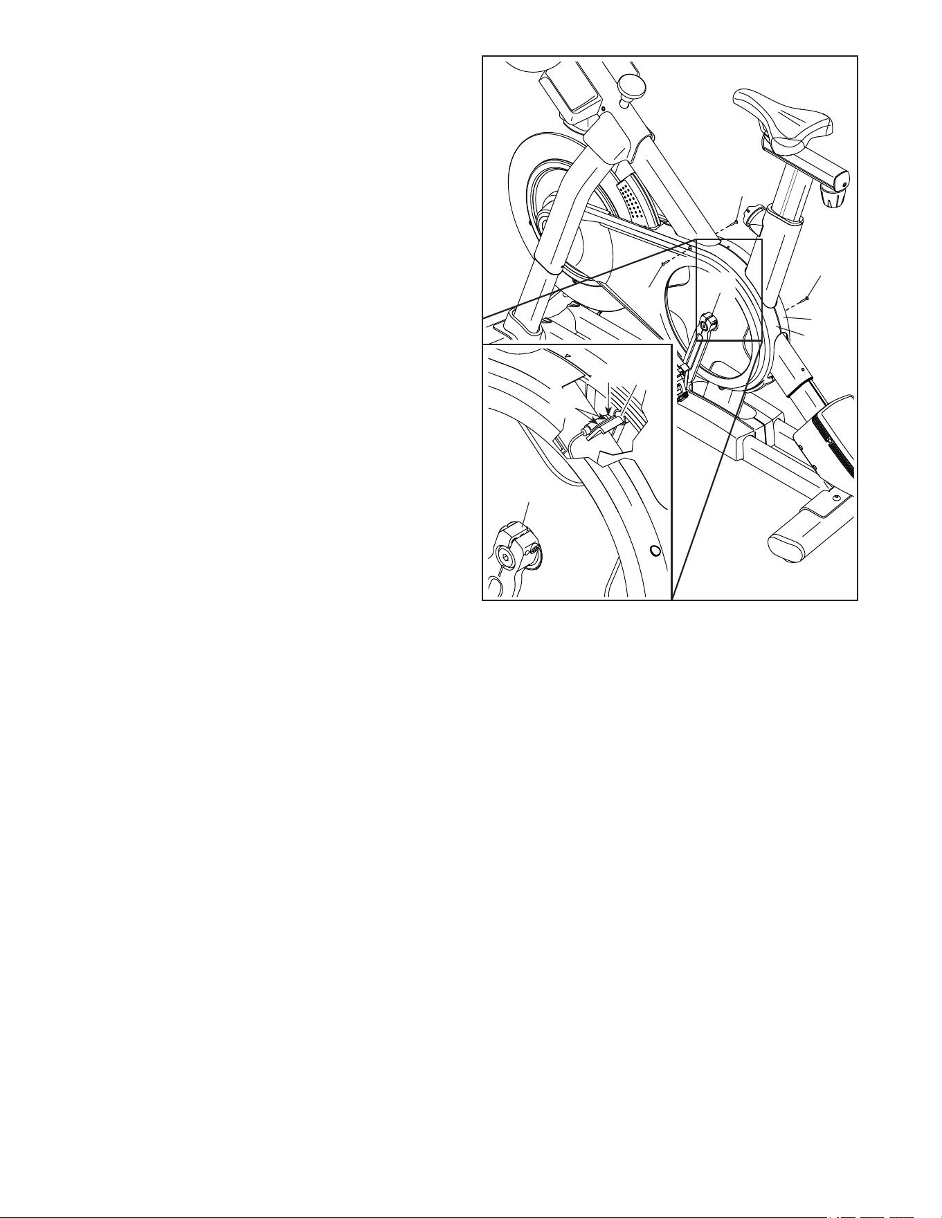
HOW TO ADJUST THE REED SWITCH
If the console does not display correct feedback, the
reed switch should be adjusted.
To adjust the reed switch, first press the power
switch and unplug the power adapter. Next, remove
the three indicated #8 x 5/8" Screws (17) from the
Right and Left Shields (30, 32).
Then, carefully pull the tops of the Right and Left
Shields (30, 32) apart a few inches.
See the inset drawing. Slightly loosen the two indi-
cated #8 x 1/2" Screws (57). Next, rotate the Left
Crank Arm (21) until a Pulley Magnet (137) is aligned
with the Reed Switch (115). Slide the Reed Switch
slightly toward or away from the Pulley Magnet. Then,
retighten the Screws.
Plug in the power adapter, press the power switch,
and rotate the Left Crank Arm (21) for a moment.
Repeat these actions until the console displays correct
feedback.
When the reed switch is correctly adjusted, reattach
the Right and Left Shields (30, 32).
17
30
32
17
17
21
115
83
21
137
115
57
33
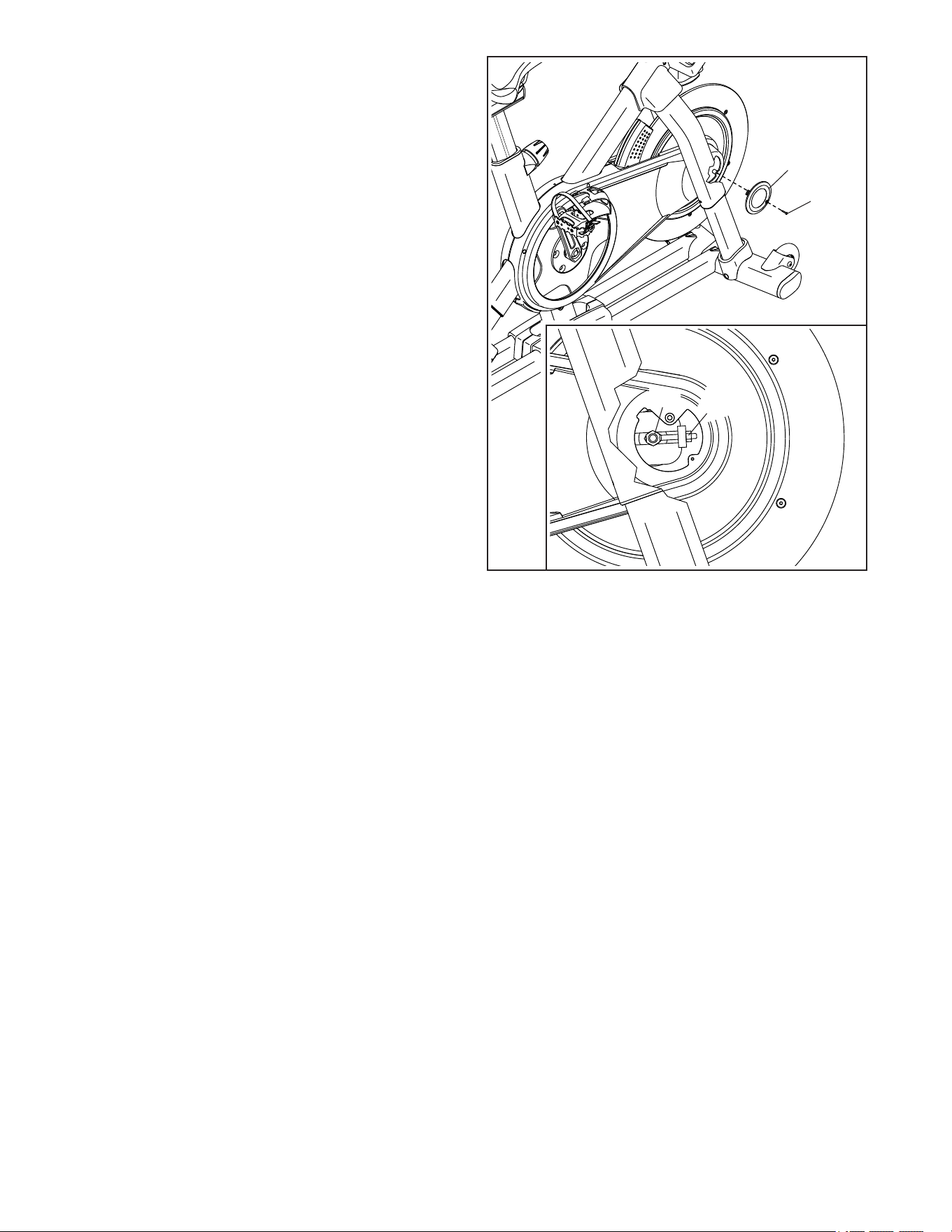
HOW TO ADJUST THE DRIVE BELT
If you can feel the pedals slip while you are pedaling,
even when the resistance is adjusted to the highest
setting, the drive belt may need to be adjusted.
To adjust the drive belt, first press the power switch
and unplug the power adapter. Then, follow the
instructions below. Note: The drawings show only the
right side of the studio cycle.
Remove the indicated #8 x 5/8" Screw (17) and the
Shield Cover (31) from each side of the studio cycle.
Next, loosen the M10 Axle Nut (27) on each side of
the studio cycle, and tighten the Adjustment Nut (26)
on each side of the studio cycle one half turn. Then,
firmly retighten the M10 Axle Nuts.
Plug in the power adapter, press the power switch,
and pedal the studio cycle to test the adjustment. If
necessary, repeat the above actions until the pedals no
longer slip.
When the drive belt is properly adjusted, reattach the
shield covers.
17
31
26
27
34
These guidelines will help you to plan your exercise
program. For detailed exercise information, obtain a
reputable book or consult your physician. Remember,
proper nutrition and adequate rest are essential for
successful results.
EXERCISE INTENSITY
Whether your goal is to burn fat or to strengthen your
cardiovascular system, exercising at the proper inten-
sity is the key to achieving results. You can use your
heart rate as a guide to find the proper intensity level.
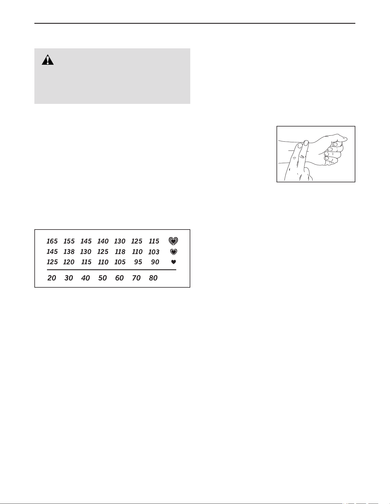
The chart below shows recommended heart rates for
fat burning and aerobic exercise.
To find the proper intensity level, find your age at the
bottom of the chart (ages are rounded off to the near-
est ten years). The three numbers listed above your
age define your “training zone.” The lowest number is
the heart rate for fat burning, the middle number is the
heart rate for maximum fat burning, and the highest
number is the heart rate for aerobic exercise.
Burning Fat—To burn fat effectively, you must exer-
cise at a low intensity level for a sustained period of
time. During the first few minutes of exercise, your
body uses carbohydrate calories for energy. Only
after the first few minutes of exercise does your body
begin to use stored fat calories for energy. If your
goal is to burn fat, adjust the intensity of your exer-
cise until your heart rate is near the lowest number in
your training zone. For maximum fat burning, exercise
with your heart rate near the middle number in your
training zone.
Aerobic Exercise—If your goal is to strengthen your
cardiovascular system, you must perform aerobic
exercise, which is activity that requires large amounts
of oxygen for prolonged periods of time. For aerobic
exercise, adjust the intensity of your exercise until
your heart rate is near the highest number in your
training zone.
HOW TO MEASURE YOUR HEART RATE
To measure your heart
rate, exercise for at
least four minutes.
Then, stop exercis-
ing and place two
fingers on your wrist
as shown. Take a
six-second heartbeat
count, and multiply the
result by 10 to find your heart rate. For example, if your
six-second heartbeat count is 14, your heart rate is 140
beats per minute.
WORKOUT GUIDELINES
Warming Up—Start with 5 to 10 minutes of stretch-
ing and light exercise. A warm-up increases your body
temperature, heart rate, and circulation in preparation
for exercise.
Training Zone Exercise—Exercise for 20 to 30 min-
utes with your heart rate in your training zone. (During
the first few weeks of your exercise program, do not
keep your heart rate in your training zone for longer
than 20 minutes.) Breathe regularly and deeply as you
exercise; never hold your breath.
Cooling Down—Finish with 5 to 10 minutes of stretch-
ing. Stretching increases the flexibility of your muscles
and helps to prevent post-exercise problems.
EXERCISE FREQUENCY
To maintain or improve your condition, complete
three workouts each week, with at least one day of
rest between workouts. After a few months of regular
exercise, you may complete up to five workouts each
week, if desired. Remember, the key to success is to
make exercise a regular and enjoyable part of your
everyday life.
WARNING: Before beginning this
or any exercise program, consult your physi-
cian. This is especially important for persons
over age 35 or persons with pre-existing
health problems.
EXERCISE GUIDELINES

35
Key No. Qty. Description Key No. Qty. Description
PART LIST
Model No. NTEX02422-INT.3 R0522A
1 1 Frame
2 1 Base
3 1 M10 Washer
4 1 Roller
5 1 M6 Shoulder Screw
6 2 Inner Leg Sleeve
7 1 Handlebar Post
8 1 Console Support
9 1 M8 x 32mm Screw
10 1 Console
11 1 Console Bracket
12 4 M4 x 8mm Machine Screw
13 1 Saddle Post
14 2 Hand Weight
15 1 M12 Crank Screw
16 1 Pulley
17 40 #8 x 5/8" Screw
18 4 M10 x 20mm Flat Head Bolt
19 1 Crank/Right Crank Arm/Right Pedal
20 1 Pivot Axle
21 1 Left Crank Arm/Left Pedal
22 1 Flywheel Assembly
23 1 Handlebar Cap
24 2 Pivot Bushing
25 1 Drive Belt
26 2 Adjustment Assembly
27 2 M10 Axle Nut
28 2 Post Clamp
29 1 Right Base Cover
30 1 Right Shield
31 2 Shield Cover
32 1 Left Shield
33 1 Right Disc
34 1 Right Incline Motor Cover
35 1 Left Incline Motor Cover
36 1 Upper Incline Motor Cover
37 1 Left Disc
38 1 Hand Weight Tray
39 1 Handlebar Post Cap
40 1 Accessory Tray
41 1 M8 Saddle Screw
42 1 Saddle Nut
43 2 Carriage Cap
44 3 One-wire Grommet
45 1 Right Saddle Post Sleeve
46 1 Left Saddle Post Sleeve
47 1 Right Handlebar Post Sleeve
48 1 Left Handlebar Post Sleeve
49 2 Wheel
50 1 Adjustment Arm
51 1 Resistance Disc
52 1 Lower Saddle Clamp
53 1 Upper Saddle Clamp
54 1 Saddle
55 4 Anchored Zip Tie
56 1 Roller Axle
57 18 #8 x 1/2" Screw
58 1 Upper Leg
59 2 Lower Leg
60 4 #8 x 1/3" Screw
61 4 M8 x 15mm Screw
62 2 Outer Leg Sleeve
63 1 Frame Bearing Set
64 2 Leg Cover
65 1 Ground Screw
66 4 Large Leg Bushing
67 1 Carriage
68 2 Leg Spacer
69 4 Small Leg Bushing
70 1 Right Grip
71 1 Left Grip
72 1 Right Control
73 1 Left Control
74 1 Shaft Cover
75 1 Shaft Cover Sleeve
76 4 Stabilizer Cap
77 2 Foot
78 2 Leveling Foot
79 1 Controller
80 1 Controller Cover
81 3 M3 x 6mm Machine Screw
82 1 Resistance Motor
83 2 M10 x 38mm Washer
84 1 M12 x 25mm Cap Screw
85 2 Post Knob Cap
86 5 Clip Nut
87 2 Incline Motor Bushing
88 1 Incline Motor Spacer
89 1 Incline Motor
90 1 Magnet Bracket
91 1 Right Magnet Bracket Cover
92 1 Left Magnet Bracket Cover
93 4 M8 x 12mm Patch Screw
94 1 M10 x 55mm Screw
95 2 M4 Set Screw
96 2 M6 x 25mm Screw
97 1 Handlebar
98 2 M8 x 50mm Bolt
99 2 M8 Locknut
100 2 Post Knob

36
101 1 Carriage Knob
102 4 M6 x 20mm Machine Screw
103 4 M4 x 10mm Machine Screw
104 2 Incline Motor Sleeve
105 2 Cleat Assembly
106 1 Tray Cover
107 2 M4 x 15mm Machine Screw
108 3 M6 Washer
109 1 Front Bracket Mount
110 1 Wire Protector
111 2 Upper/Lower Pivot Disc
112 1 Center Pivot Disc
113 2 Inner Pivot Bushing
114 1 Rear Bracket Mount
115 1 Reed Switch/Wire
116 1 Reed Switch Clip
117 1 Left Base Cover
118 1 Power Receptacle
119 1 Power Adapter
120 1 Power Cord
121 1 Upper Brake Bushing
122 1 Lower Wire
123 1 Upper Wire
124 1 Extension Wire
125 1 Control Wire
126 2 M8 x 12mm Screw
127 6 M8 Large Washer
128 2 M5 Nut
129 1 M5 x 8mm Screw
130 1 #6 x 5/8" Screw
131 1 Adjustment Block
132 2 M4 x 10mm Blunt Screw
133 2 M10 x 20mm Hex Screw
134 1 Plastic Spacer
135 4 M10 Locknut
136 1 Shoe Pin
137 2 Pulley Magnet
138 2 M6 x 15mm Screw
139 1 Thrust Washer
140 1 Brake Knob Cap
141 1 M6 Locknut
142 1 Lower Brake Knob
143 1 Lower Brake Bushing
144 1 Spring Stop
145 1 Brake Spring
146 2 M4 x 6mm Screw
147 1 Brake Shaft
148 1 Roll Pin
149 1 E-ring
150 1 Brake Shoe
151 1 Upper Leg Axle
152 1 M25 Locknut
153 1 Mount Cover
154 1 Lower Console Cover
155 1 Upper Console Cover
156 8 Crown Fastener/Screw
157 4 M6 x 15mm Cap Screw
158 1 O-ring
159 1 Power Switch
160 4 M10 x 20mm Screw
161 8 M10 x 35mm Screw
* – User’sManual
* – Studio Cycle Tools
Key No. Qty. Description Key No. Qty. Description
Note: Specifications are subject to change without notice. For information about ordering replacement parts, see
the back cover of this manual. *These parts are not illustrated.
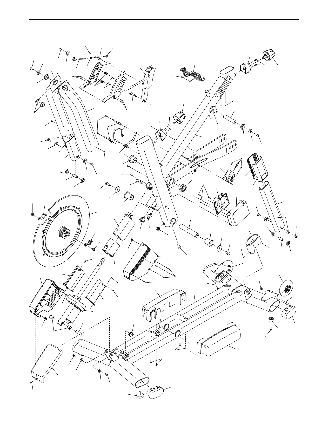
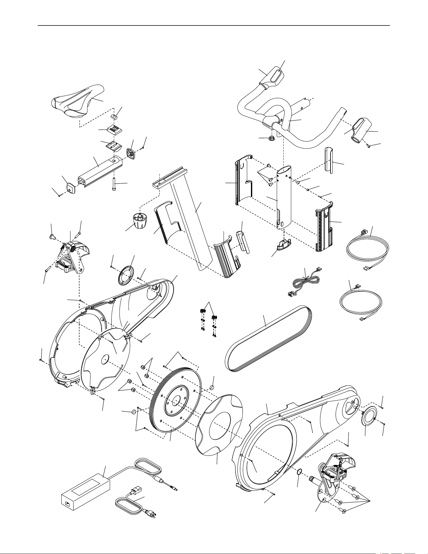
37
EXPLODED DRAWING A
Model No. NTEX02422-INT.3 R0522A
1
12
9
20
24
24
83
84
83
6
133
79
81
82
59
80
2
36
35
17
87
88
89
34
17
17
17
17
64
64
69
69
29
17
17
138
138
108
108
86
44
44
74
75
57
55
63
63
17
17
85
100
115
116
133
104
104
5
50
51
128
129
130
128
131
60
90
92
86
57
91
127
61
61
68
57
44
118
159
26
22
27
66
126
127
151
26
27
59
60
61
62
95
95
58
66
126
127
66
61
127
127
68
69
69
6
62
12
85
100
65
122
17
77
76
98
99
49
49
78
76
117
17
17
86
86
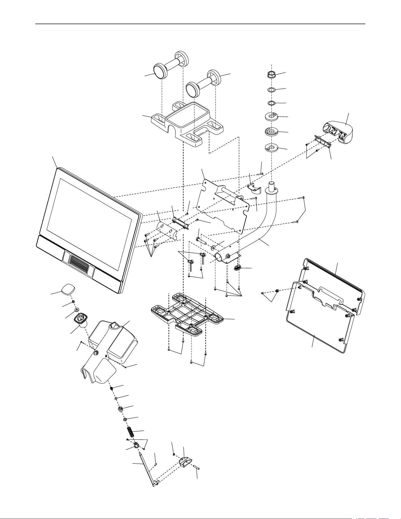
38
EXPLODED DRAWING B
Model No. NTEX02422-INT.3 R0522A
107
101
46
45
28
43
42
43
52
54
53
67
41
13
70
72
71
73
97
17
132
132
125
25
30
17
17
17
17
31
17
33
16
135
135
57
57
57
32
19
158
18
17
17
17
31
23
137
137
57
57
57
37
120
119
21
96
96
15
123
124
107
28
47
39
48
7
93
4
56
93
105
39
EXPLODED DRAWING C
Model No. NTEX02422-INT.3 R0522A
14
14
40
57
57
142
108
141
140
11
106
110
102
102
102
153
113
113
103
3
103
154
156
155
103
157
17
114
17
8
17
55
94
111
111
112
152
139
134
38
109
10
17
143
149
147
150
136
148
146
145
144
121
160
161
Part No. 439932 R0522A Printed in China © 2022 iFIT Inc.
To order replacement parts, please see the front cover of this manual. To help us assist you, be prepared to
provide the following information when contacting us:
• the model number and serial number of the product (see the front cover of this manual)
• the name of the product (see the front cover of this manual)
• the key number and description of the replacement part(s) (see the PART LIST and the EXPLODED DRAWING
near the end of this manual)
ORDERING REPLACEMENT PARTS
This electronic product must not be disposed of in municipal waste. To
preserve the environment, this product must be recycled after its useful life
as required by law.
Please use recycling facilities that are authorized to collect this type of waste in
your area. In doing so, you will help to conserve natural resources and improve
European standards of environmental protection. If you require more information
about safe and correct disposal methods, please contact your local city office or the
establishment where you purchased this product.
RECYCLING INFORMATION