INSTRUCTIONS FOR:
COMPRESSOR -
500LTR BELT DRIVE 7.5hp 3ph
2-STAGE WITH CAST CYLINDERS
MODEL No: SAC55075B
Original Language Version
SAC55075B Issue: 1 - 24/12/14
© Jack Sealey Limited
IMPORTANT: PLEASE READ THESE INSTRUCTIONS CAREFULLY. NOTE THE SAFE OPERATIONAL REQUIREMENTS, WARNINGS & CAUTIONS. USE THE PRODUCT
CORRECTLY AND WITH CARE FOR THE PURPOSE FOR WHICH IT IS INTENDED. FAILURE TO DO SO MAY CAUSE DAMAGE AND/OR PERSONAL INJURY AND WILL
INVALIDATE THE WARRANTY. KEEP THESE INSTRUCTIONS SAFE FOR FUTURE USE.
Thank you for purchasing a Sealey product. Manufactured to a high standard, this product will, if used according to these
instructions, and properly maintained, give you years of trouble free performance.
Guide to symbols
Warning: Electricity
Warning: Hot Surface
Warning: Automatic
start up
Wear ear protection
Read the instruction
manual before use
DO NOT open the air
cock before an air hose
is attached
DO NOT operate the
compressor with
enclosure displaced
Ensure oil level
is
correctbeforerstuse
1. SAFETY
1.1. ELECTRICAL SAFETY
WARNING! It is the responsibility of the owner and the
operator to read, understand and comply with the following: You
must check all electrical products, before use, to ensure that
they are safe. You must inspect power cables, plugs, sockets
and any other connectors for wear or damage. You must ensure
that the risk of electric shock is minimised by the installation of
appropriate safety devices. A Residual Current Circuit Breaker
(RCCB) should be incorporated in the main distribution board.
We also recommend that a Residual Current Device (RCD) is
used. It is particularly important to use an RCD with portable
products that are plugged into a supply which is not protected by
an RCCB. If in any doubt consult a qualified electrician. You may
obtain a Residual Current Device by contacting your Sealey
dealer. You must also read and understand the following
instructions concerning electrical safety.
1.1.1. The Electricity at Work Act 1989 requires that all portable
electrical appliances, if used on business premises, are tested
by a qualified electrician, using a Portable Appliance Tester
(PAT), at least once a year.
1.1.2. The Health & Safety at Work Act 1974 makes owners of
electrical appliances responsible for the safe condition of those
appliances and the safety of the appliance operators. If in any
doubt about electrical safety, contact a qualified electrician.
1.1.3. Ensure that the insulation on all cables and on the appliance is
safe before connecting it to the power supply. See 1.1.1. and
1.1.2. and use a Portable Appliance Tester.
1.1.4. Ensure that cables are always protected against short circuit
and overload.
1.1.5. Regularly inspect power supply cables and plugs for wear or
damage and check all connections to ensure that none is loose.
1.1.6. Important: Ensure that the voltage marked on the appliance
matches the power supply to be used and that the plug is fitted
with the correct fuse (see 1.1.10. below).
1.1.7. DO NOT pull or carry the appliance by the power cable.
1.1.8. DO NOT pull the plug from the socket by the cable.
1.1.9. DO NOT use worn or damaged cables, plugs or connectors.
Immediately have any faulty item repaired or replaced by a
qualified electrician.
WARNING! ELECTRICAL INSTALLATION TO A 3 PHASE
415VOLT SUPPLY MUST ONLY BE CARRIED OUT BY A
QUALIFIED ELECTRICIAN.
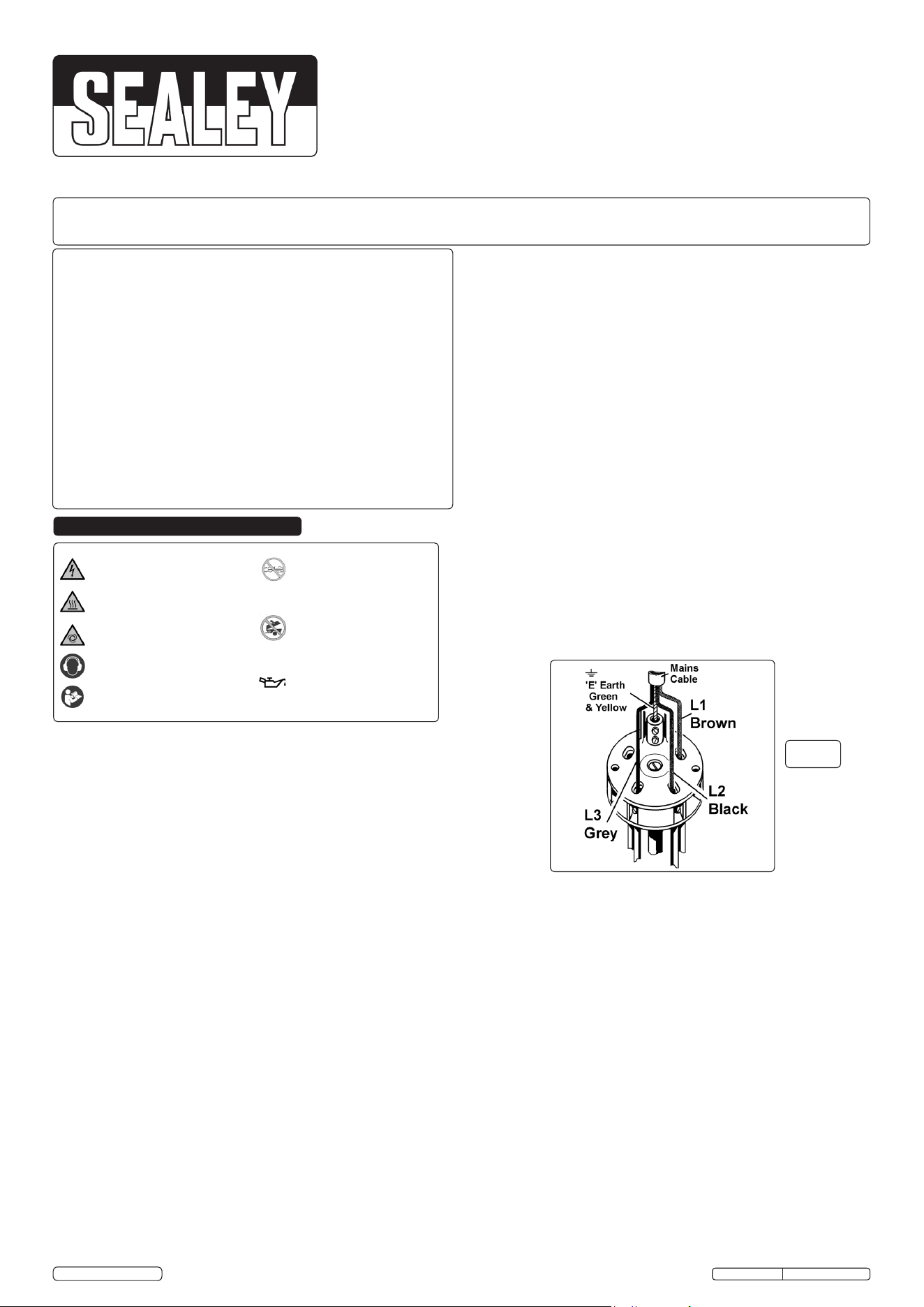
1.1.10 This product must be fitted with a 3 phase plug wired as
illustration in (fig.1), wired to an appropriately fused supply.
Connect GREEN/YELLOW wire to Earth ‘E’
Connect BROWN wire to L1 Terminal.*
Connect BLACK wire to L2 Terminal.*
Connect the GREY wire to L3 Terminal.*
WARNING! IT IS ESSENTIAL TO OBSERVE PULLEY DIRECTION
ON INITIAL START UP, SEE fig.2 AND PULLEY GUARD. IF
INCORRECT, STOP IMMEDIATELY AND CONSULT A QUALIFIED
ELECTRICIAN TO INVERT 2 PHASES*.
*NOTE: The cable core colours found in the mains cable on this
compressor are consistent with Amendment 2 to 7671:2001. When
completed, check there are no bare wires, that all wires have been
connected correctly and the cable restraint is tight.
1.1.11 DO NOT use this product with an extension cable.
IMPORTANT USER INFORMATION!
Over-current protection of the power circuit is required in
accordance with 7.2 of EN 60204-1:2006. The supply
disconnecting device to be in accordance with 5.3 of
EN 60204-1:2006. Ask a qualified electrician about compliance.
1.2. GENERAL SAFETY
3 Familiarise yourself with the application and limitations of the
compressor.
3 Ensure the compressor is in good order and condition before
use. If in any doubt do not use the unit and contact an
electrician/service agent.
WARNING! Compressor must only be serviced by an
authorised agent. DO NOT tamper with, or attempt to
adjust, pressure switch or safety valve.
3 Before moving, or maintaining the compressor ensure it is
unplugged from the mains supply and that the air tank pressure
has been vented.
3 Maintain the compressor in good condition and replace any
damaged or worn parts. Use genuine parts only. Unauthorised
parts may be dangerous and will invalidate your warranty.
3 Read the instructions relating to any accessory to be used
with this compressor. Ensure the safe working pressure of
any air appliance used exceeds compressors output
pressure. If using a spray gun, check that the area selected
for spraying is provided with an air change system/ventilation.
3 Ensure the air supply valve is turned off before disconnecting
the air supply hose.
3 Use the compressor in a well ventilated area and ensure it is
placed on a firm surface.
fig.1
Heavy duty three phase compressors suitable for the professional
workshop. Two stage pump system coupled with a 7.5hp motor
maximises performance to keep running costs low compared to
single stage single phase models. 500ltr tank allows for longer
continuous air tool operation and less start ups so using less power,
saving on running costs. Pumps feature heavy duty full cast
cylinders, capped by alloy heads for improved heat dissipation and
long life. Heavy duty drive guards protect belt and flywheel, that is
designed to force air over the pump to aid cooling. Supplied with full
CE certification, test certificates and operating/maintenance manual.
Model: ........................................................................... SAC55075B
Motor Output (HP): .................................................................... 7.5hp
Voltage/Phase: ...................................................................... 415-3hp
Input current: ................................................................................ 16A
Speed (rpm): .............................................................................. 1280
Air Displacement (cfm/Lm): ................................................. 29.3(380)
Max Free Air Delivery (cfm/Lm): ..........................................22.6(640)
Max Pressure (psi/bar): ........................................................... 145/10
Tank Capacity (L): ........................................................................ 500
Dimensions (WxDxH) (mm): ........... ................ .....2000 x 700 x 1230
Net Weight (kg): ........................................................................255kg
SAC55075B Issue: 1 - 24/12/14
Original Language Version
© Jack Sealey Limited
2. INTRODUCTION
4. OPERATION
fig.3
3. SPECIFICATIONS
4.1. Preparation
4.1.1. Remove compressor from the packaging.
4.1.2. Confirm that the mains voltage corresponds with the voltage
shown on the compressor data plate. Fit a suitable 3 pin
industrial plug - see section 1.1.10. of the Safety Instructions.
4.1.3. Take care to transport the compressor correctly, DO NOT
overturn it or lift it with hooks or ropes.
4.1.4.Positionthecompressoronaat,horizontalsurfaceand
ensure it is securely bolted down. Site in a well ventilated
area, protected against atmospheric pollution and not in a
placesubjecttoexplosionhazard.
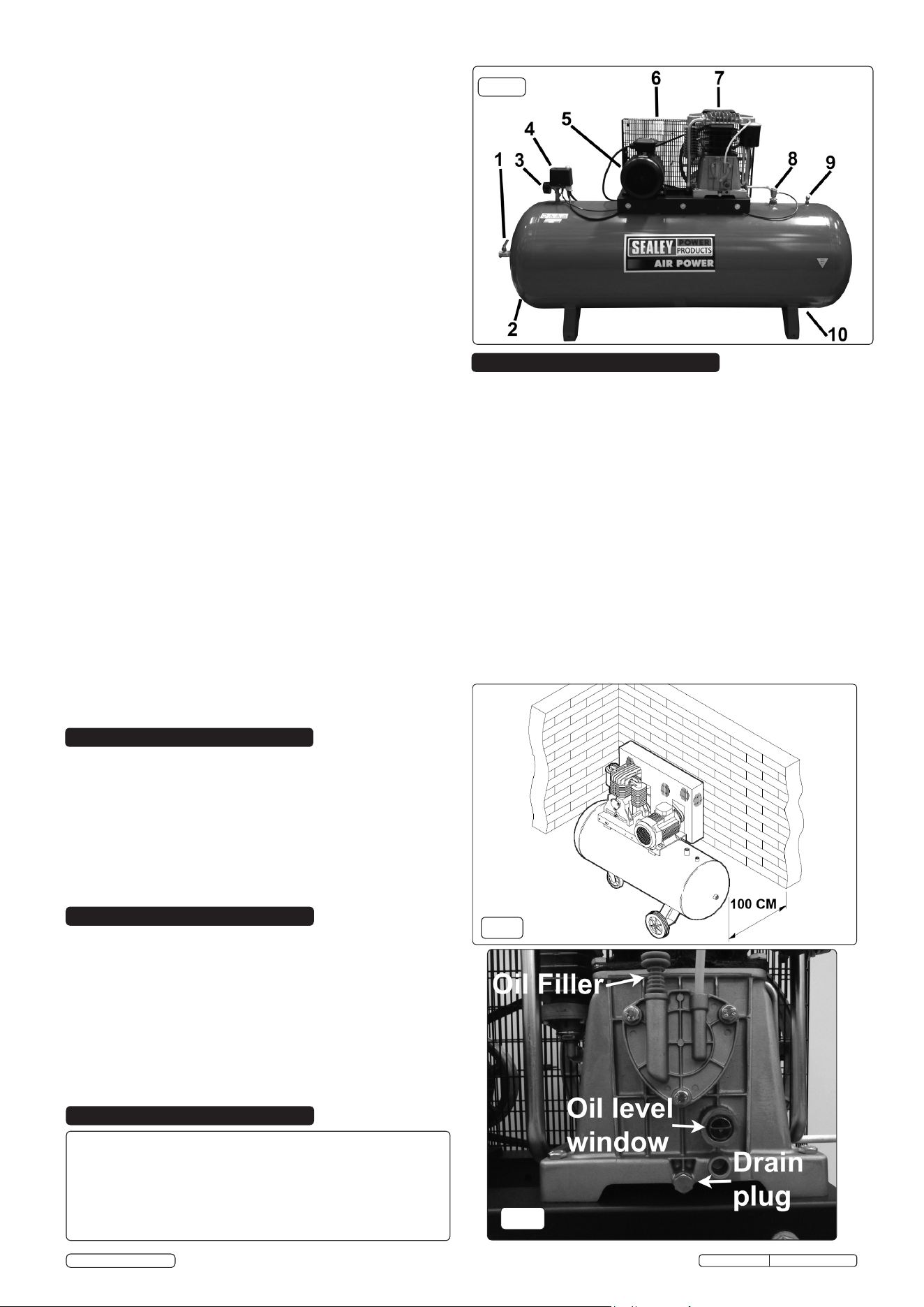
4.1.5. Toensuregoodventilationandefcientcooling,thecompressor’s
beltguardmustbeatleast100cmfromanywall(g.3).
4.1.6. Remove the plastic transit plug from the oil filler hole, if fitted,
(fig.4) and replace it with the dipstick. It is a push fit.
4.1.7. Before using the compressor, check the oil level in the
sight glass in fig.2. If the oil is not up to the max. mark, it should
be topped up with synthetic oil (see section 5.7. for
recommended oils). We DO NOT recommend using mineral oil
in these compressors. DO NOT overfill.
7 DO NOT operate the compressor without an air filter.
7 DO NOT allow anyone to operate the compressor unless
they have received full instructions.
WARNING! The air tank is a pressure vessel and the
following safety measures apply:
7 No welding operations are to be carried out on any
pressurised parts of the vessel.
7 DO NOT tamper with the safety valve, DO NOT modify or alter
the tank in any way and DO NOT strap anything to the tank.
7 DO NOT subject the tank to impact, vibration or to heat and
DO NOT allow contact with abrasives or corrosives.
3 Drain condensation from tank and inspect inside walls for
corrosion as per the maintenance schedule and have a
detailed tank inspection carried out annually. The tank shell
must not fall below the certified thickness at any point.
WARNING! If an electrical fuse blows, ensure it is replaced
with an identical fuse type and rating.
3 When not in use for a prolonged period, and if possible, store
the compressor carefully in a safe, dry, childproof location.
4. CONTENTS
1. Direct compressed air outlet.
2. Tank.
3. Pressure gauge.
4. Pressure switch.
5. Electric motor.
6. Belt guard
7. Compressor unit.
8. Non return valve.
9. Safety valve.
10. Condensate drain.
fig.2
fig.4
GENERAL SAFETY CONTINUED:
3 Keep tools and other items away from the compressor when
it is in use, and keep area clean and clear of unnecessary
items.
3 Ensure the air hose is not tangled, twisted or pinched.
3 Keep children and unauthorised persons away from the
working area.
7 DO NOT dis-assemble compressor for any reason. The unit
must be checked by qualified personnel only.
7 DO NOT use the compressor outdoors, or in damp, or wet,
locations
7 DO NOT operate within the vicinity of flammable liquids,
gases or solids.
7 DO NOT touch compressor cylinder, cylinder head or pipe
from head to tank as these may be hot.
7 DO NOT use this product to perform a task for which it has
not been designed.
7 DO NOT deface the certification plate attached to the
compressor tank.
7 DO NOT cover the compressor or restrict air flow around the
unit whilst operating.
q DANGER! DO NOT direct the output jet of air towards people
or animals.
In order to keep the compressor in good working condition,
periodic maintenance is essential.
IMPORTANT! Failure to carry out maintenance tasks may
invalidate the warranty on your compressor.
WARNING! Before performing any maintenance operation,
switch off the compressor, disconnect from electricity
supply and release all air from the tank (except for 5.3.a)
5.1. Operations to be carried out after the first 50 working hours:
a) Check that all bolts/nuts are tight, particularly those retaining
the crankcase and cylinder head.
b) Replace the lubricating oil - see para 5.5.a. shown in fig.4.
5.2. Operations to be carried out weekly:
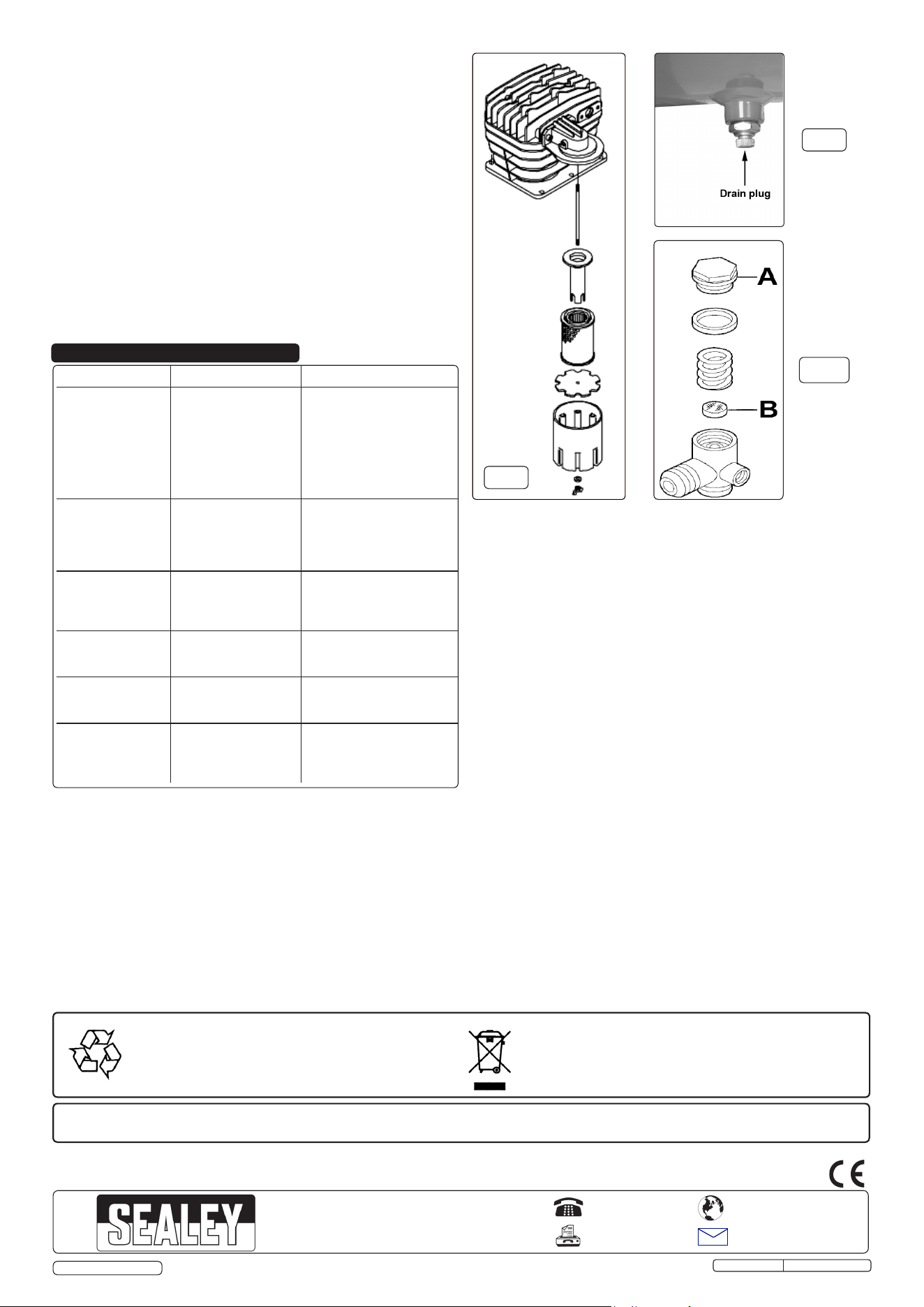
a) Drain condensation by opening the valve located under the
tank (fig.7). Place a container under the valve and open the
valve by turning anti-clockwise.
WARNING! Take care if there is still pressure inside the cylinder
as water could flow out with considerable force.
Recommended pressure 1 - 2bar max.
b) Check oil level and, if necessary, top up.
5.3. Operations to be carried out every 50 hours
(or more frequently, if the compressor operates in a very
dusty atmosphere):
a) Remove the air filter element (fig.4). Using stored air from
the compressor's tank, clean the filter with compressed air.
(Wear eye protection and DO NOT direct air towards the
body or hands). DO NOT operate the compressor without
the filter as foreign bodies or dust could seriously damage
the pump. Replace the filter element and air filter housing.
b) Check for oil leaks.
5.4. Operations to be carried out every 100 hours:
a) Check the automatic cut-out at max. pressure and the
automatic cut-in at 2bar below.
5.5. Operations to be carried out every 400 hours:
a) Replace the lubricating oil. (Refer to fig.4) For oil
specifications see 5.7.
Remove the oil filler, then remove the oil drainer plug
draining the oil into a container. Drain when the
compressor is hot so that the oil drains rapidly and completely.
Replace oil drain plug and refill through the oil filler. DO
NOT overfill (check level at oil level window, red dot denotes
correct level.) Replace oil filler.
WARNING! Never mix different oils and DO NOT use non-
detergent/low quality oils as the compressor may be damaged.
WARNING! Dispose of waste oil only in accordance with
local authority requirements.
b) Replace air filter. (See fig.6)
c) Check all tube fittings and electrical connections.
d) Inspect pressure tank inside and out for damage or corrosion.
Maintenance Operations Weekly 50hrs 100hrs 400 hrs
Drain condensation
•
Check oil level
•
Clean intake filter
•
Check for oil leaks
•
Replace oil
•
Check cut-out
•
General cleaning of
compressor
•
Replace air filter
•
Check tube fittings and
electrical connections
•
Original Language Version
© Jack Sealey Limited
SAC55075B Issue: 1 - 24/12/14
5. MAINTENANCE
5.6. Maintenance Schedule
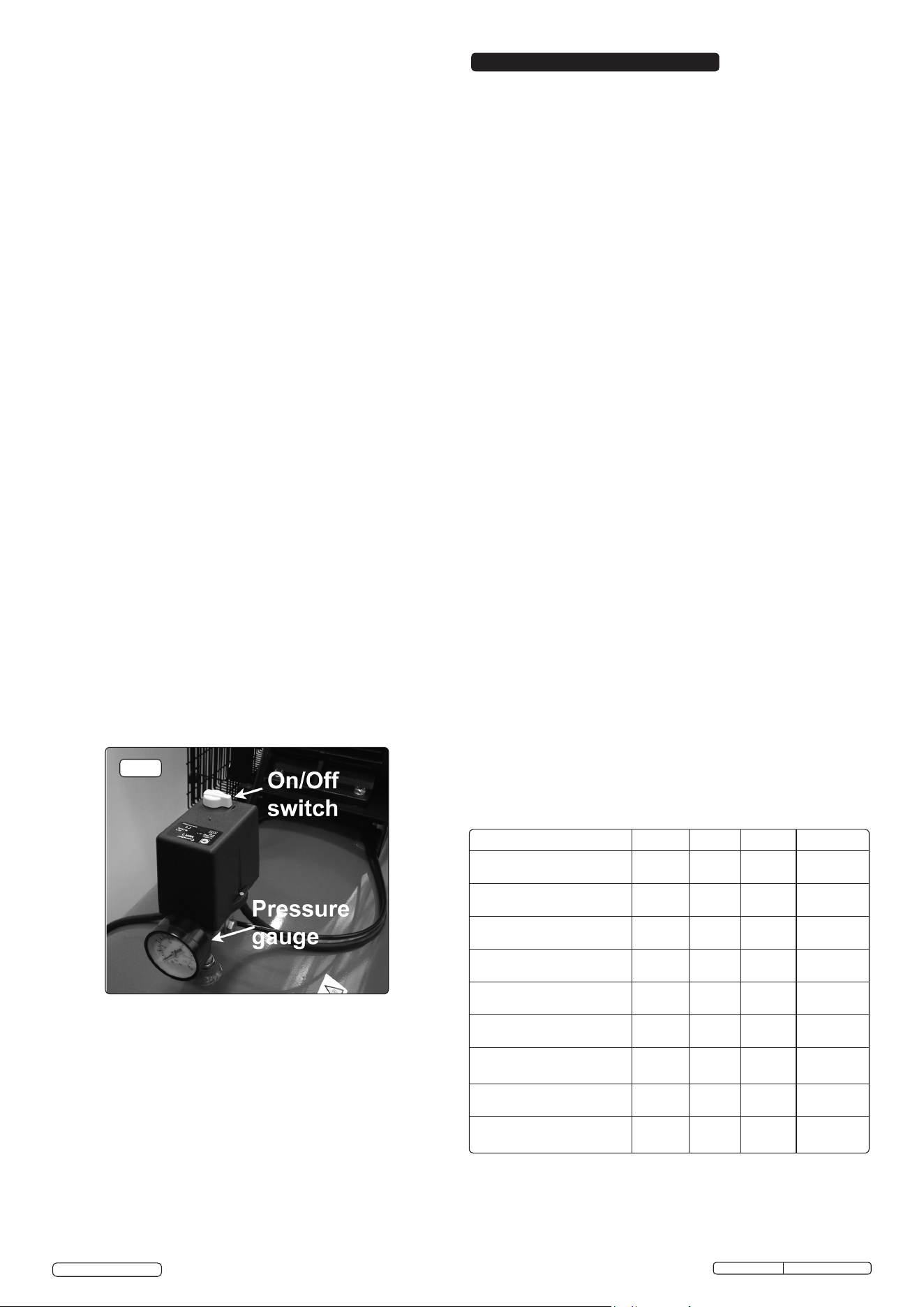
4.3. STARTING THE COMPRESSOR
4.3.1 Check that the ON/OFF switch (fig.5) is OFF in the "O" position.
4.3.2 Plug mains lead into mains supply and start the compressor by
moving the pressure switch to the ON ‘I’ position. Check the
direction of rotation (see arrow on cylinder head cover) to
confirm correct wiring of 3-phase plug.
4.3.3 When starting the compressor for the first time, leave it running
with no air tools connected to the air outlet. Make sure that
pressure in the tank rises and that the compressor stops
automatically when the maximum pressure value allowed -
written on the plate and shown on the gauge is achieved.
The compressor will now operate automatically.
The pressure switch stops the motor when the maximum
tank pressure is reached and restarts it when the pressure
falls below the minimum threshold.
4.3.4 Stop the compressor by moving the pressure switch (fig.2) to
the "O" position. The compressed air inside the compressor
head will flow out, making the restart easier and preventing the
motor from being damaged. DO NOT, other than in an
emergency, stop the compressor by switching off the mains
power, or by pulling the plug out, as the pressure relief will not
then operate and motor damage may result upon restart.
When the compressor runs correctly and is stopped correctly
there will be: (a) a whistle of compressed air when the motor
stops. (b) a protracted whistle (about 20-25 seconds) when the
compressor starts with no pressure in the tank.
WARNING! For this reason DO NOT tamper with, or adjust,
the switch or safety valve.
fig.5
4.2. Operation
WARNING! Ensure that you have read, understood and
apply Section 1 Safety Instructions.
IMPORTANT! The use of extension leads not
recommended as the resulting voltage drop reduces
motor, and therefore pump performance, and could cause
damage to the compressor.
NOTE: Take care when selecting tools for use with the
compressor. Air tool manufacturers normally express the
volume of air required to operate a tool in cubic feet per
minute (cfm). This refers to free air delivered by the
compressor (‘air out’) which varies according to the pressure
setting. DO NOT confuse this with the compressor
displacement which is the air taken in by the compressor (‘air
in’). ‘Air out’ is always less than ‘air in’ due to losses within the
compressor.
NOTE: It is our policy to continually improve products and as such we reserve the right to alter data, specifications and component parts without prior notice.
IMPORTANT: No liability is accepted for incorrect use of this product.
WARRANTY: Guarantee is 12 months from purchase date, proof of which will be required for any claim.
01284 757500
01284 703534
sales@sealey.co.uk
Sole UK Distributor, Sealey Group,
Kempson Way, Suffolk Business Park,
Bury St. Edmunds, Suffolk,
IP32 7AR
www.sealey.co.uk
Web
email
fig.8
Fault Cause Remedy
Pressure drop in the
tank.
Air leaks at
connections.
Run compressor to max.
pressure, switch off.
Brush soap solution over
connections and look for
bubbles. Tighten connections
showing leaks. If problem
persists contact Authorised
Service Agent.
Pressure switch
valve leaks when
compressor is idle.
Non-return valve seal
defective.
Discharge all tank pressure.
Referring to fig.8, unscrew
valve cap 'A'. Clean rubber
disc 'B' and its seat. Refit all
parts accurately.
Compressor stops
and does not restart.
Power failure.
Motor failure.
Check electricity supply and
fuse.
Contact Authorised Service
Agent.
Compressor does
not stop at max
pressure.
Pressure switch fault. Contact Authorised Service
Agent.
Compressor does
not reach max
pressure.
Filter clogged.
Head gasket or valve
fault.
Replace filter element.
Contact Authorised Service
Agent.
Compressor noisy
with metallic knock.
Low oil level.
Bearing or piston
damage.
Turn off and top up oil
immediately.
Contact Authorised Service
Agent.
Original Language Version
© Jack Sealey Limited
Parts support is available for this product. To obtain a parts listing and/or diagram,
please log on to www.sealey.co.uk, email sales@sealey.co.uk or telephone 01284 757500.
Environmental Protection.
Recycle unwanted materials instead of disposing of them as
waste. All tools, accessories and packaging should be sorted,
taken to a recycle centre and disposed of in a manner which
is compatible with the environment.
WEEE Regulations.
Dispose of this product at the end of its working life in compliance
with the EU Directive on Waste Electrical and Electronic Equipment.
When the product is no longer required, it must be disposed of in an
environmentally protective way. Contact your local solid waste
authority for recycling information.
SAC55075B Issue: 1 - 24/12/14
6. TROUBLESHOOTING
fig.6
fig.7
5.7. Recommended oils
Synthetic oil suitable for temperatures ranging from -5°C to 45°C:
viscosity 5W50. We do not recommend using mineral oil in these
compressors.
Part No. Qty. Description
FSO1 1ltr x 12 Compressor oil fully synthetic
FSO1S 1ltr x 1 Compressor oil fully synthetic
FSO5 5ltr x 1 Compressor oil fully synthetic
5.8. IMPORTANT WARNING - Air contaminants taken into the
compressorwillaffectoptimumperformance.Example:Bodyller
dustorpaintoverspraywillclogthepumpintakelterandmay
cause internal damage to pump/motor components. Please note
that any parts damaged by any type of contamination will not be
covered by warranty.
Inspection of pressure tank both inside and out.
Under the PRESSURE SYSTEMS SAFETY REGULATIONS 2000 it is
the responsibility of the owner of the compressor to initiate a system of
inspectionthatbothdenesthefrequencyoftheinspectionandappoints
apersonwhohasspecicresponsibilityforcarryingouttheinspection.