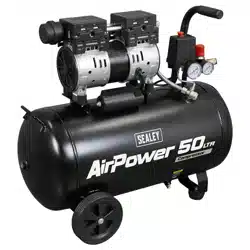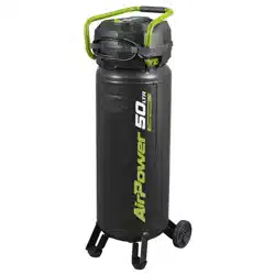
50L OIL FREE BELT DRIVE COMPRESSOR 2HP
MODEL NO: SAC05020.V3
Thank you for purchasing a Sealey product. Manufactured to a high standard, this product will, if used according to these instructions,
and properly maintained, give you years of trouble free performance.
IMPORTANT: PLEASE READ THESE INSTRUCTIONS CAREFULLY. NOTE THE SAFE OPERATIONAL REQUIREMENTS, WARNINGS & CAUTIONS. USE
THE PRODUCT CORRECTLY AND WITH CARE FOR THE PURPOSE FOR WHICH IT IS INTENDED. FAILURE TO DO SO MAY CAUSE DAMAGE AND/OR
PERSONAL INJURY AND WILL INVALIDATE THE WARRANTY. KEEP THESE INSTRUCTIONS SAFE FOR FUTURE USE.
1. SAFETY
1.1. ELECTRICAL SAFETY
WARNING! It is the responsibility of the owner and the operator to read, understand and comply with the following: You must check all
electrical products before use to ensure that they are safe. You must inspect power cables, plugs, sockets and any other connectors for wear
or damage. You must ensure that the risk of electric shock is minimised by the installation of appropriate safety devices. A Residual Current
Circuit Breaker (RCCB) should be incorporated in the main distribution board. We also recommend that a Residual Current Device (RCD) is
used. It is particularly important to use an RCD with portable products that are plugged into a supply which is not protected by an RCCB. If in
any doubt consult a qualified electrician. You must also read and understand the following instructions concerning electrical safety:
1.1.1. Over/current Protection: The user has to make provision for the installation of the over-current protection of the power circuit.
1.2. Electrical disconnecting device: The user has to make provisions for the installation of the electrical disconnecting device of the power
circuit. The supply disconnection device is to be in accordance with EN 60204-1:2006.
1.2.1. The Health & Safety at Work Act 1974 makes owners of electrical appliances responsible for the safe condition of those appliances
and the safety of the appliance operators. If in any doubt about electrical safety, contact a qualified electrician.
1.2.2. Ensure that the insulation on all cables and on the appliance is safe before connecting it to the power supply.
1.2.3. If the replacement of the supply cord is necessary, this has to be done by the manufacturer or his agent in order to avoid a safety hazard.
1.2.4. Ensure that cables are always protected against short circuit and overload.
1.2.5. Regularly inspect power supply cables and plugs for wear or damage and check all connections to ensure that none are loose.
1.2.6. Important: Ensure that the voltage marked on the appliance matches the power supply to be used and that the plug is fitted with the
correct fuse.
▲ DANGER! If the power cable for this equipment is damaged, it must be replaced by the manufacturer or its after-sales service or similarly
trained personnel to avoid danger.
8 DO NOT pull or carry the appliance by the power cable.
8 DO NOT pull the plug from the socket by the cable.
8 DO NOT use worn or damaged cables, plugs or connectors. Immediately have any faulty item repaired or replaced by a qualified electrician.
NOTE: If using a transformer to supply the compressor, it must be rated at a minimum of 2kVA to allow the compressor to run efficiently.
1.2.7. Power tool plugs must match the outlet. Never modify the plug in any way. DO NOT use any adaptor plugs with earthed (grounded) power
tools. Unmodified plugs and matching outlets will reduce risk of electric shock. Avoid body contact with earthed or grounded surfaces,
such as pipes, radiators, ranges and refrigerators. There is an increased risk of electric shock if your body is earthed or grounded.
8 DO NOT expose power tools to rain or wet conditions. Water entering a power tool will increase the risk of electric shock.
8 DO NOT abuse the cord. Never use the cord for carrying, pulling, or unplugging the power tool. Keep cord away from the heat, oil, sharp
edges or moving parts. Damaged or entangled cords increase the risk of electric shock.
1.2.8. When operating a power tool outdoors, use an extension cord suitable for outdoor use. Use of a cord suitable for outdoor use reduces the
risk of electric shock.
1.2.9. If operating a power tool in a damp location is unavoidable, use a residual current device (RCD) protected supply. Use of an RCD reduces
the risk of electric shock.
1.2.10. Save all warning and instructions for future reference.
1.3. GENERAL POWER TOOL SAFETY WARNINGS
1.3.1. WARNING read all safety warnings, instructions, illustrations and specications provided with this power tool. Failure to follow all
instructions listed below may result in electric shock, re and/or serious injury.
9 Before you connect the equipment to the mains supply make sure that the data on the rating plate are identical to the mains data.
9 Familiarise yourself with the application and limitations of the compressor.
9 Ensure the compressor is in good order and condition before use. If in any doubt DO NOT use the unit and contact your Sealey Stockist.
9 Keep work area clean and well lit. Cluttered or dark area invites accidents.
8 DO NOT operate power tools in explosive atmospheres, such as in the presence of flammable liquids, gases or dust. Power tools create
sparks which may ignite the dust or fumes.
1.4. WORK AREA SAFETY
9 Keep children and bystanders away whilst operating a power tool. Distractions can cause you to lose control.
9 Operation must be with all guards, covers, lids and enclosures correctly in place.
9 Fully assemble the compressor before using for the first time.
9 The concentration of processed gases that can displace breathing air shall be kept within acceptable levels. Reference EN 12021 for
acceptable levels of contaminants in breathing air.
9 Remove from mains supply when performing maintenance or inspections.
Original Language Version
© Jack Sealey Limited
Refer to
instruction
manual
Warning:
Electricity
Warning:
Hot surface
Wear ear
protection
Indoor
use only
DO NOT
open air cock
before air
hose attached
Wear eye
protection
SAC05020.V3 Issue 3 (3) 22/04/24
Warning:
Auto Start Up
Wear a mask Work in
progress

1.5. PERSONAL SAFETY
9 Stay alert, watch what you are doing and use common sense when operating a power tool.
8 DO NOT use a power tool whilst you are tired or under the inuence of drugs, alcohol, or medication. A moment inattention whilst
operating power tools may result in serious injury.
9 Prevent unintentional starting. Ensure the switch is in the o position before connecting to power source and/or battery pack, picking
up or carrying the tool. Carrying power tools with your ngers on the switch or energising power tools that have the switch on invites
accidents.
8 DO NOT let familiarity gained from frequent use of tools allow you to become complacent and ignore tool safety principles. A careless
action can cause severe injury within a fraction of a second.
8 DO NOT force the power tool. Use the correct power tool for your application. The correct power tool will do the job better and safer at
the rate for which it was designed.
8 DO NOT use the power tool if the switch does not turn it on and o. Any power tool that cannot be controlled with the switch is
dangerous and must be repaired.
9 Disconnect the plug from the power source and/or remove the battery pack, if detachable, from the power tool before making any
adjustments, changing accessories, or storing power tools. Such preventive safety measures reduce the risk of starting the power tool
accidentally.
9 Store idle power tools out of the reach of children and DO NOT allow persons unfamiliar with these power tools or these instructions to
operate the power tool. Power tools are dangerous in the hands of untrained users.
9 Maintain power tools and accessories. Check for misalignment or biding of the moving parts, breakage of parts and any other condition
that may aect the power tool’s operation. If damages, have the power tool repaired before use. Many accidents are caused by poorly
maintained power tools.
9 Use the power tool, accessories and tool bits etc, in accordance with these instructions, taking into account the working conditions and
the work to be performed. Use of the power tool for operations dierent from those intended could result in a hazardous situation.
9 Keep handles and grasping surfaces dry, clean and free from oil and grease. Slippery handles and grasping surfaces do not allow for
safe handling and control of the tool in unexpected situations.
1.6. SPECIFIC AIR COMPRESSOR SAFETY
9 Maintain the compressor in good condition and replace any damaged or worn parts. Use genuine parts only. Unauthorised parts may
be dangerous and will invalidate your warranty.
8 DO NOT carry out any welding operations on any pressurised part of the vessel.
9 Before moving, or maintaining the compressor ensure it is unplugged from the mains supply and that the air tank pressure has been vented.
9 Have your power tool serviced by a qualied repair person using only identical replacement parts. This will ensure that the safety of the
power tool is maintained.
9 Delivery hoses should be fitted with a safety cord.
9 The compressor may only be used in suitable rooms (with good ventilation and an ambient temperature from +5°C to +40°C). Ensure there
is no dust, acids, vapours, explosive gases, or inflammable gases in the room. The air intake should be from a clean, outside air source.
9 Read the instructions relating to any accessory to be used with this compressor.
9 Ensure the safe working pressure of any air appliance used exceeds compressors output pressure. If using a spray gun, check that the
area selected for spraying is provided with an air change system/ventilation.
9 Ensure the air supply valve is turned o before disconnecting the air supply hose to move transportable compressor - use handle only.
8 DO NOT attempt to lift or move the compressor by any other means.
9 Use the compressor in a well ventilated area and ensure it is placed on a rm surface.
9 Keep tools and other items away from the compressor when it is in use, and keep area clean and clear of unnecessary items.
9 Ensure the air hose is not tangled, twisted or pinched.
9 Keep children and unauthorised persons away from the working area.
8 DO NOT dis-assemble compressor for any reason. The unit must be checked by qualied personnel only.
8 DO NOT use the compressor outdoors, or in damp, or wet, locations.
8 DO NOT operate within the vicinity of ammable liquids, gases or solids.
8 DO NOT touch compressor cylinder head or pipe from head to tank as these may be hot.
8 DO NOT use this product to perform a task for which it has not been designed.
8 DO NOT deface the certication plate attached to the compressor tank.
8 DO NOT cover the compressor or restrict air ow around the unit whilst operating.
9 DANGER! DO NOT direct the output jet of air towards people or animals.
8 DO NOT operate the compressor without an air lter.
8 DO NOT allow anyone to operate the compressor unless they have received full instructions.
WARNING! The air tank is a pressure vessel and the following safety measures apply:
8 DO NOT tamper with the safety valve, DO NOT modify or alter the tank in any way and DO NOT strap anything to the tank.
8 DO NOT subject the tank to impact, vibration or to heat and DO NOT allow contact with abrasives or corrosives.
9 Drain condensation from tank daily and inspect inside walls for corrosion every three months and have a detailed tank inspection
carried out annually. The tank shell must not fall below the certied thickness at any point.
9 When not in use, store the compressor carefully in a safe, dry, childproof location.
9 When the compressor is not in use, it should be switched o, disconnected from the mains supply and the air drained from the tank.
9 Under the PRESSURE SYSTEMS SAFETY REGULATIONS 2000 it is the responsibility of the owner of the compressor to initiate a
system of inspection that both denes the frequency of the inspection and appoints a person who has specic responsibility for
carrying out the inspection.
1.7. NOISE
9 The declared noise emission value(s) have been measured in accordance with a standard test method and may be used for comparing
one tool with another. The declared vibration total values and the declared noise emission values may also be used in a preliminary
assessment of exposure.
9 The noise emissions during actual use of the power tool can dier from the declared values depending on the ways in which the tool is
used, especially what kind of workpiece is processed. The need to identify safety measures to protect the operator that are based on
an estimation of exposure in the actual condition of use.
© Jack Sealey Limited
Original Language Version
SAC05020.V3 Issue 3 (3) 22/04/24
2. INTRODUCTION
Aluminium cylinder head with cast iron cylinder gives added resistance to wear. Fitted with fully automatic pressure cut-out switch and air
regulator with gauge. Pump head directly coupled to heavy-duty induction motor for reliable and quiet operation. Precision welded receiver tank
manufactured to meet Pressure Vessel Directive. Suitable for all general-purpose workshop applications. Vertical tank saves oor space which
makes it perfect for small workshops. Fitted with 3-pin plug.
3. SPECIFICATION
MODEL NO: SAC05020.V3
Air Displacement cfm(L/min): 6.35(180) Receiver Capacity: 50L
Fuse Rating: 13A Size (W x D x H): 370mm x 355mm x 1340mm
Max. Free Air Delivery cfm(L/min): 3.17(90) Supply: 230V/50Hz/13A
Maximum Pressure: 145psi (10bar) Intermediate pressure/temperature Normal environment
Motor Output: 2hp Inlet discharge pressure/temperature 8-10bar
Nett Weight: 25kg Maximum pressure ratio Not applicable
Noise Level: 96/85dB(A) Maximum speed 3500rpm
Noise Test Code EN ISO2151:2008 Media Air
Outlet: Quick Release Coupling Permissible Inclination 0°
Phase: 1ph Corrosion allowance 0.5mm
Plug Type: 3-Pin BS Wall thickness 2.75mm
Power Supply Cable Length: 1.8m
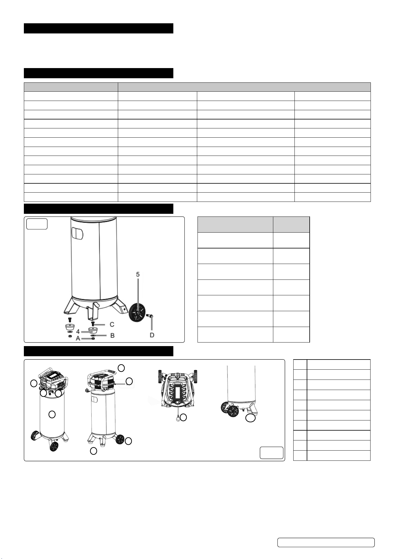
4. CONTENTS
PARTS QUANTITY
1. Compressor 1
2. Nuts (A) 2
3. Washers (B) 2
4. Feet (2) 2
5. Wheels 2
6. Hexagon bolts (C) 2
7. Wheel bolts (D) 2
FIG.1
5. PREPARATION
1 Transport handle
2 Quick coupling
3 Pressure vessel
4 Supporting foot
5 Wheel
6 Pressure regulator
7 Pressure gauges
8 Safety valve
9 On/O switch
10 Drain tap
10
9
1
2
3
4
5
6
7
8
FIG.2
5.1. ATTACHMENT OF WHEELS AND FEET (FIG.1)
5.1.1. Feed the wheel bolt 7 (D) through the hole in the wheel (5).
5.1.2. Feed the wheel bolt (D) through the hole in the wheel linkage.
5.1.3. Fasten the wheel (5) with the wheel bolt 7(D). If necessary use a combination spanner for this (not included).
5.1.4. Repeat for other wheel.
5.2. ATTACHING THE FEET
5.2.1. Fit the supplied supporting foot (4) with 2 hexagonal bolts 6(C), washers,3(B) and two flange nuts 2(A) as in fig.1.
Original Language Version
© Jack Sealey Limited
SAC05020.V3 Issue 3 (3) 22/04/24
6. OPERATION
6.1. MAINS CONNECTION
6.1.1. The compressor is equipped with a mains cable with protective contact plug. This can be connected to any 230 V~ 50 Hz protective
contact socket, with fuse protection of at least 13A.
6.1.2. Before commissioning, ensure that the mains voltage matches with the operating voltage and the machine’s power rating on the type plate.
6.1.3. Long supply cables, extensions, cable reels, etc. cause a drop in voltage and can impede motor start up.
6.1.4. In the case of temperatures below +5°C, motor starting can be endangered by sluggishness.
6.2. ON/ OFF SWITCH
6.2.1. The compressor is switched on by setting the on/off switch (FIG.2 9) to position I.
6.2.2. The compressor is switched off by setting the on/off switch (FIG.2 9) to position O.
6.3. PRESSURE ADJUSTMENT
6.3.1. The actual pressure in the pressure vessel (FIG.2.3) is shown on the pressure gauge (FIG.2.7).
6.3.2. The desired pressure can be adjusted with the pressure regulator (FIG.2.6).
6.3.3. The pressure at the quick coupling (FIG.2.2) can be adjusted from 0 to 10 bar.
6.4. PRESSURE SWITCH ADJUSTMENT
6.4.1. The pressure switch is set in the factory.
6.4.2. Cut-in pressure approx. 8 bar.
6.4.3. Cut-out pressure approx.10 bar.
6.5. FITTING THE COMPRESSED AIR HOSE (not included)
6.5.1. Push the compressed air hose into one of the two quick-couplers (FIG.2.2). The compressed air hose latches into place.
6.6. REMOVING THE COMPRESSED AIR HOSE (not included)
6.6.1. Press the coupling ring on the quick coupler (FIG.2.2) towards the compressor. The compressed air hose pops out of the quick-
coupling (FIG.2.2).
NOTE In order to prevent injury, hold the compressed air hose tightly whilst disconnecting the hose as there will be residual air pressure
inside the airline.
7. MAINTENANCE
WARNING! Before performing any maintenance operation, switch the compressor off, disconnect from electricity supply and release all air
from the tank. In order to keep the compressor in good working condition, periodical maintenance is essential.
IMPORTANT WARNING - Air contaminants taken into the compressor will aect optimum performance. Example: Body ller dust or
paint over-spray will clog the pump intake lter and may cause internal damage to pump/motor components.
NOTE: When performing any maintenance on the unit ensure that the symbols and wording shown below are clearly and prominently
displayed in the working area.
DO NOT START
MAINTENANCE
WORK IN
PROGRESS
7.1. OPERATIONS TO BE CARRIED OUT DAILY:
a) Drain condensation, place a container under the valve and open the valve by turning anti-clockwise (FIG.2.10). Re-tighten the valve.
b) Check that all nuts and bolts are tight, particularly those retaining the crankcase and cylinder head.
7.2. OPERATIONS TO BE CARRIED OUT EVERY 100 HOURS: (or more frequently, if the compressor operates in a very dusty atmosphere):
7.2.1. Remove the air filter element by unscrewing the filter holder and prising open the holder. Clean it by blowing through with an air line at low
pressure, from the clean side. Alternatively, wash it in soapy water, rinse and dry. DO NOT operate the compressor without the filter as
foreign bodies or dust could seriously damage the pump.
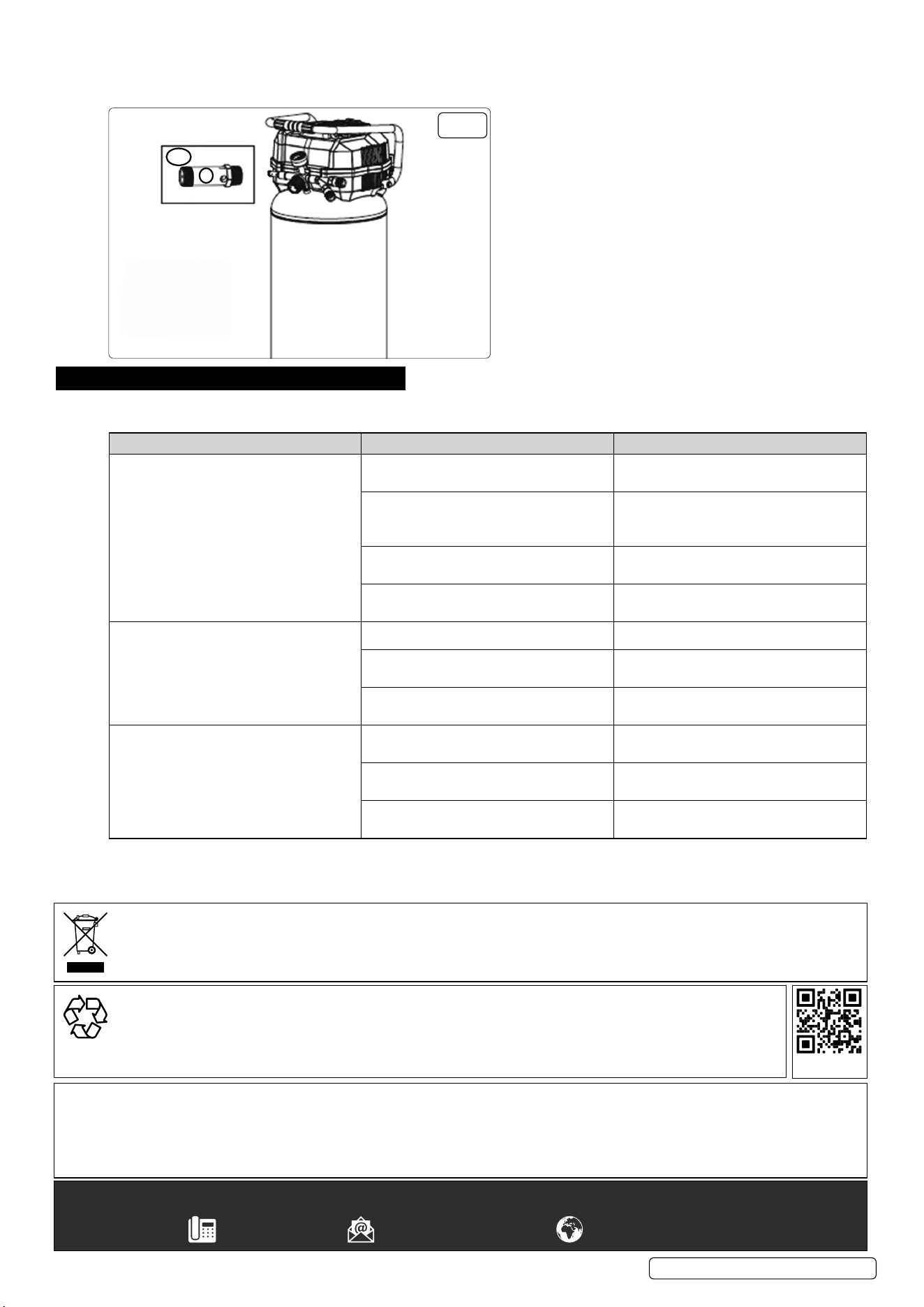
7.2.2. SAFETY VALVE NOTE: When checking the safety valve ALWAYS WEAR SAFETY GLASSES.
7.2.2.1. To check the operation of the safety valve the air tank will need to be full. Unscrew the valve cap and gently pull it outwards (FIG.3). This
should release air under pressure. Release the valve cap and this should stop the air out flow immediately.
7.2.2.2. If the safety valve DOES NOT work in this manner, STOP the air compressor immediately and have the air compressor checked/serviced
by an authorised service centre.
7.3. OPERATIONS TO BE CARRIED OUT EVERY 200 HOURS:
7.3.1. Check the automatic cut-out at maximum pressure.
7.4. OPERATIONS TO BE CARRIED OUT EVERY 500 HOURS:
a) Replace air filters.
b) Check all tube fittings and electrical connections.
IMPORTANT! Failure to carry out maintenance tasks may invalidate the warranty on your compressor.
7.5. SCHEDULED MAINTENANCE TABLE
MAINTENANCE OPERATIONS DAILY 100 HRS. 200 HRS. 500 HRS.
Drain condensation
•
Clean intake filter
•
Check cut-out
•
Check Safety relief
valve operation (Fig.3.8/8.A relief
spring assy)
•
Replace air filters. Check all fittings
and connections
•
Original Language Version
© Jack Sealey Limited
SAC05020.V3 Issue 3 (3) 22/04/24
7.6. INSPECTION OF PRESSURE TANK BOTH INSIDE AND OUT
Under the pressure systems safety regulations 2000 it is the responsibility of the owner of the compressor to initiate a system of inspection
that both defines the frequency of the inspection and appoints a person who has specific responsibility for carrying out the inspection
Pressure
relief valve
FIG.3
8A
8
8. TROUBLESHOOTING
WARNING! Before performing any troubleshooting operation, switch the compressor off, disconnect from electricity supply and release all
air from the tank. In order to keep the compressor in good working condition, periodical maintenance is essential.
FAULT CAUSE REMEDY
The compressor does not start. Mains voltage is not available. Check the cable, mains plug, fuse and
socket.
Mains voltage is too low. Make sure that the extension cable is not
too long. Use an extension cable with large
enough wires.
Outside temperature is too low. Never operate with an outside temperature
of below 0°C.
Motor is overheated. Allow the motor to cool down. If necessary
remedy the cause of the overheating.
The compressor starts but there is no
pressure.
Non-return valve leaking. Replace the non-return valve.
The seals are damaged. Check the seals and have any damaged
seals replaced by a service centre.
The drain screw for condensate leaks. Tighten the screw by hand. Check the seal
on the screw and replace if necessary.
The compressor starts, pressure is shown
on the pressure gauge, but the tools do
not operate.
The hose connections have a leak. Check the compressed air hose and tools
and replace if necessary.
A quick coupling has a leak. Check quick coupling, replace if
necessary.
Insucient pressure set on the pressure
regulator.
Increase the set pressure with the
pressure regulator.
Original Language Version
© Jack Sealey Limited
SAC05020.V3 Issue 3 (3) 22/04/24
Sealey Group, Kempson Way, Suffolk Business Park, Bury St Edmunds, Suffolk. IP32 7AR
01284 757500 sales@sealey.co.uk www.sealey.co.uk
ENVIRONMENT PROTECTION
Recycle unwanted materials instead of disposing of them as waste. All tools, accessories and packaging should be
sorted, taken to a recycling centre and disposed of in a manner which is compatible with the environment. When
the product becomes completely unserviceable and requires disposal, drain any uids (if applicable) into approved
containers and dispose of the product and uids according to local regulations.
REGISTER YOUR
PURCHASE HERE
Note: It is our policy to continually improve products and as such we reserve the right to alter data, specifications and component parts without prior
notice. Please note that other versions of this product are available. If you require documentation for alternative versions, please email or call
our technical team on technical@sealey.co.uk or 01284 757505.
Important: No Liability is accepted for incorrect use of this product.
Warranty: Guarantee is 12 months from purchase date, proof of which is required for any claim.
WEEE REGULATIONS
Dispose of this product at the end of its working life in compliance with the EU Directive on Waste Electrical and Electronic Equipment
(WEEE). When the product is no longer required, it must be disposed of in an environmentally protective way. Contact your local solid
waste authority for recycling information.