BELT DRIVE AIR COMPRESSOR 3HP WITH CAST
CYLINDERS & WHEELS
MODEL NO: SAC1503B, SAC1103B, SAC1153B,
SAC1203B
Thank you for purchasing a Sealey product. Manufactured to a high standard, this product will, if used according to these instructions,
and properly maintained, give you years of trouble free performance.
IMPORTANT: PLEASE READ THESE INSTRUCTIONS CAREFULLY. NOTE THE SAFE OPERATIONAL REQUIREMENTS, WARNINGS & CAUTIONS. USE
THE PRODUCT CORRECTLY AND WITH CARE FOR THE PURPOSE FOR WHICH IT IS INTENDED. FAILURE TO DO SO MAY CAUSE DAMAGE AND/OR
PERSONAL INJURY AND WILL INVALIDATE THE WARRANTY. KEEP THESE INSTRUCTIONS SAFE FOR FUTURE USE.
1. SAFETY
1.1. ELECTRICAL SAFETY
WARNING! It is the responsibility of the owner and the operator to read, understand and comply with the following: You must check
all electrical products, before use, to ensure that they are safe. You must inspect power cables, plugs, sockets and any other connectors
for wear or damage. You must ensure that the risk of electric shock is minimised by the installation of appropriate safety devices.
A Residual Current Circuit Breaker (RCCB) should be incorporated in the main distribution board. We also recommend that a Residual
Current Device (RCD) is used. It is particularly important to use an RCD with portable products that are plugged into a supply which is
not protected by an RCCB. If in any doubt consult a qualified electrician. You must also read and understand the following instructions
concerning electrical safety.
1.1.1. The Electricity at Work Act 1989 requires that all portable electrical appliances, if used on business premises, are tested
by a qualified electrician, using a Portable Appliance Tester (PAT), at least once a year.
1.1.2. The Health & Safety at Work Act 1974 makes owners of electrical appliances responsible for the safe condition of those
appliances and the safety of the appliance operators. If in any doubt about electrical safety, contact a qualified electrician.
1.1.3. Ensure that the insulation on all cables and on the appliance is safe before connecting it to the power supply. See 1.1.1. and use a
Portable Appliance Tester.
1.1.4. Ensure that cables are always protected against short circuit and overload.
1.1.5. Regularly inspect power supply cables and plugs for wear or damage and check all connections to ensure
that none is loose.
1.1.6. IMPORTANT: Ensure that the voltage marked on the appliance matches the power supply to be used and
that the plug is fitted with the correct fuse - see fuse rating at right.
8 DO NOT pull or carry the appliance by the power cable.
8 DO NOT pull the plug from the socket by the cable.
8 DO NOT use worn or damaged cables, plugs or connectors. Immediately have any faulty item repaired or
replaced by a qualified electrician.
1.1.7. ThisproductisttedwithaBS1363/A3pinplug.
If the cable or plug is damaged during use, switch the electricity supply and remove from use.
Ensurethatrepairsarecarriedoutbyaqualiedelectrician.
ReplaceadamagedplugwithaBS1363/A3pinplug.Ifindoubtcontactaqualiedelectrician.
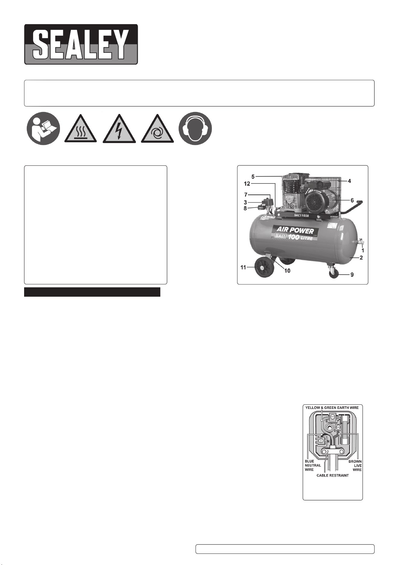
a)ConnecttheGREEN/YELLOWearthwiretotheearthterminal‘E’.
b)ConnecttheBROWNlivewiretotheliveterminal‘L’.
c)ConnecttheBLUEneutralwiretotheneutralterminal‘N’.
Ensure that the cable outer sheath extends inside the cable restraint and that the restraint is tight.
Sealeyrecommendthatrepairsarecarriedoutbyaqualiedelectrician.
IMPORTANT! The use of extension leads to connect these compressors to the mains is not recommended as the resulting
voltage drop reduces motor, and therefore pump performance.
Original Language Version
© Jack Sealey Limited
Refer to
instruction
manual
Warning: Hot
surface
Warning:
Electricity
Warning:
Automatic
startup
Wear ear
protection
SAC1103B illustrated.
(others will differ
slightly)
1. Direct compressed
air outlet.
2. Tank
3. Pressure reducer.
4. Belt guard.
5. Compressor unit.
6. Electric motor.
7. Pressure switch.
8. Pressure gauge.
9. Pivot wheel.
10. Condensate drain.
11. Wheel.
12. Check valve.
Replacement fuse
rating: 13 AMP
SAC1503B, SAC1103B, SAC1153B, SAC1203B Issue:5(H,F)16/05/23

1.2. GENERAL SAFETY
9 Familiarise yourself with the application and limitations of the compressor.
9 Ensure the compressor is in good order and condition before use. If in any doubt DO NOT use the unit and contact your Sealey Stockist.
WARNING! Item must be serviced by an authorised agent. DO NOT tamper with or attempt to adjust pressure switch or safety valve.
8 DO NOT carry out any welding operations on any pressurised part of the vessel.
9 Before moving, or maintaining the compressor ensure it is unplugged from the mains supply and that the air tank pressure has been
vented.
9 Maintain the compressor in good condition and replace any damaged or worn parts. Use genuine parts only. Unauthorised parts may be
dangerous and will invalidate your warranty.
9 Read the instructions relating to any accessory to be used with this compressor. Ensure the safe working pressure of any air appliance
used exceeds compressors output pressure. If using a spray gun, check that the area selected for spraying is provided with an air change
system/ventilation.
9 Ensure the air supply valve is turned off before disconnecting the air supply hose to move a transportable compressor use the handle
only.Liftthecompressorsothatthefrontleggivesenoughclearanceformanoeuvringbutmaintainunit’scentreofgravityinfrontofthe
wheels. DO NOT attempt to lift or move the compressor by any other means.
9 Use the compressor in a well ventilated area and ensure it is placed on a firm surface.
9 Keep tools and other items away from the compressor when it is in use, and keep area clean and clear of unnecessary items.
9 Ensure the air hose is not tangled, twisted or pinched.
9 Keep children and unauthorised persons away from the working area.
9 Only move the compressor by the handle (if portable).
8 DO NOT dis-assemble compressor for any reason. The unit must be checked by qualified personnel only.
8 DO NOT use the compressor outdoors, or in damp, or wet, locations.
8 DO NOT operate within the vicinity of flammable liquids, gases or solids.
8 DO NOT touch compressor cylinder, cylinder head or pipe from head to tank as these may be hot.
8 DO NOT use this product to perform a task for which it has not been designed.
8 DO NOT deface the certification plate attached to the compressor tank.
8 DO NOT cover the compressor or restrict air flow around the unit whilst operating.
▲ DANGER! DO NOT direct the output jet of air towards people or animals.
8 DO NOT operate the compressor without an air filter.
8 DO NOT allow anyone to operate the compressor unless they have received full instructions.
WARNING! The air tank is a pressure vessel and the following safety measures apply:
8 DO NOT tamper with the safety valve, DO NOT modify or alter the tank in any way and DO NOT strap anything to the tank.
8 DO NOT subject the tank to impact, vibration or to heat and DO NOT allow contact with abrasives or corrosives.
9 Drain condensation from tank daily and inspect inside walls for corrosion every three months and have a detailed tank inspection carried
out annually. The tank shell must not fall below the certified thickness at any point.
WARNING! If an electrical fuse blows, ensure it is replaced with an identical fuse type and rating.
9 When not in use, store the compressor carefully in a safe, dry, childproof location.
9 When the compressor is not in use, it should be switched off, disconnected from the mains supply and the air drained from the tank.
9 Under the PRESSURE SYSTEMS SAFETY REGULATIONS 2000 it is the responsibility of the owner of the compressor to initiate a
system of inspection that both defines the frequency of the inspection and appoints a a person who has specific responsibility for carrying
out the inspection.
2. i INTRODUCTION
Suitable for the professional workshop, these units are fitted with a genuine 3hp motor. Twin capacitors and a centrifugal switch aid
trouble-free start-up on a 13A supply. Pumps feature heavy-duty full cast cylinders, capped by alloy heads for improved heat dissipation
and long-life. Heavy-duty drive guards protect belt and flywheel that is designed to force air over the pump to aid cooling. Supplied with
fullCEcertification,testcertificatesandoperating/maintenancemanual.
3. i SPECIFICATION
Model: .......................................SAC1503B ................... SAC1103B .................... SAC1153B ..................SAC1203B
AirDisplacementcfm(L/min): .... 13.4(380) ......................13.4(380) ...................... 13.4(380) ....................13.4(380)
Fuse Rating: .........................................13A ...............................13A ................................13A ............................. 13A
MaximumFreeAirDeliverycfm(L/min): 8.8(249) ................8.8(249) ........................8.8(249) ...................... 8.8(249)
Maximum Pressure: .............145psi(10bar) ...............145psi(10bar) ................145psi(10bar) ............. 145psi(10bar)
Minimum Rated Supply: .......................13A ...............................13A ................................13A ............................. 13A
Motor Output: .......................................3hp ...............................3hp ................................3hp ..............................3hp
Outlet: .................. Quick Release Coupling ..Quick Release Coupling . 1/2”BSPFemaleTap .. 1/2”BSPFemaleTap
Phase: ..................................................1ph ...............................1ph ................................1ph ..............................1ph
Plug Type: .......................................... 3-Pin .............................3-Pin .............................3-Pin ...........................3-Pin
Power Supply Cable Length: .............. 1.8m .............................1.8m ..............................1.8m ............................1.8m
Receiver Capacity: ...............................50L .............................100L ..............................150L ............................200L
Size (W x D x H): .....1020 x 390 x 740mm ...1010 x 470 x 860mm ....1320 x 400 x 820mm ..1440 x 440 x 865mm
Speed: ..........................................1630rpm .......................1630rpm ........................1630rpm ..................... 1630rpm
Supply: ........................................230V/13A ..................... 230V/13A ...................... 230V/13A ....................230V/13A
4. ASSEMBLY
4.1. Remove compressor from packaging and inspect for shortages/damage. If items are missing or damaged contact your supplier.
4.2. Save the packing material for future transportation of the compressor. We recommend that you store the packing in a safe location, at
least for the period of the guarantee. Then, if necessary, it will be easier to send the compressor to the service centre.
4.3. Assemblethexedwheels/castorwheel/rubberfeettothecompressorasrequired(seeg.1).
4.4. Confirm that the mains voltage corresponds with the voltage shown on the compressor data plate.
4.5. Positionthecompressoronaatsurfaceorwithamaximumpermissibleinclinationof10°(g.2).Siteinawellventilatedarea,
Original Language Version
© Jack Sealey Limited
SAC1503B, SAC1103B, SAC1153B, SAC1203B Issue:5(H,F)16/05/23
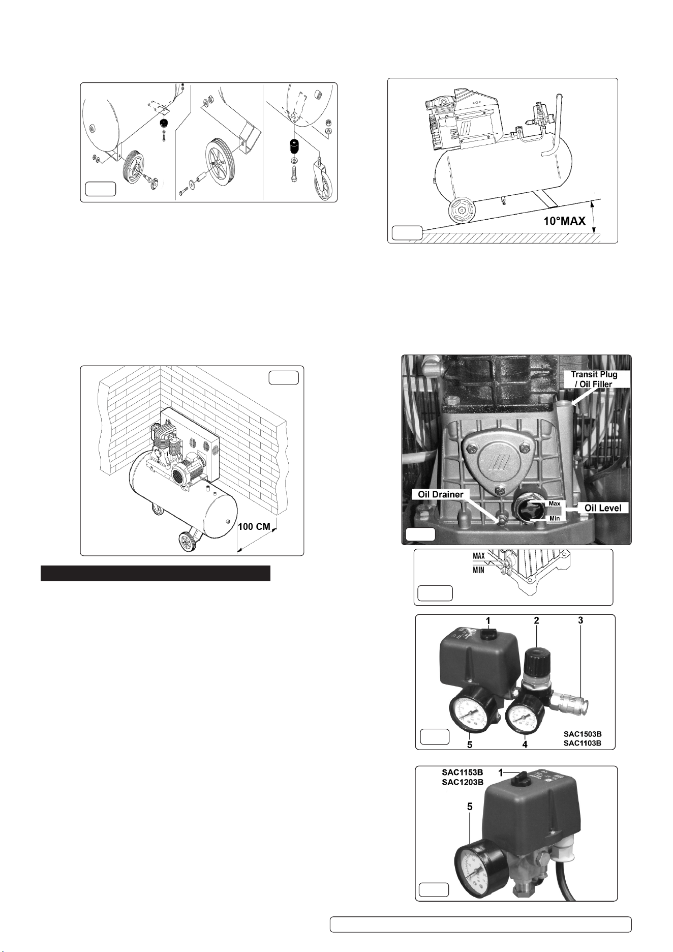
protected against atmospheric pollution and not in a place subject to explosion hazard. If the surface is inclined and smooth,
check if the compressor moves whilst in operation – if it does, secure the wheels with two wedges. If the surface is in a raised position,
make sure it cannot fall, securing it in a suitable way.
4.6. Toensuregoodventilationandecientcooling,thecompressor’sbeltguardmustbeatleast100cmfromanywall(g.3).
Compressorswithxedfeet,shouldnotberigidlysecuredtotheoor.Inthiscase,itisadvisedtot4anti-vibrationsupports(optional
extra).
4.7. Take care to transport the compressor correctly, DO NOT overturn it or lift it with hooks or ropes.
4.8. Removetheplastictransitplugfromtheoilfillerhole(fig.4)andreplaceitwiththefiller/breatherplug.Itisapushfit,ensurethatitis
pushed fully home.
4.9. Before using the compressor, check the oil level by observing the sight glass as shown in fig.4. If the oil is not up to the max mark it
shouldbetoppedupwithsyntheticoilsuitablefortemperaturesrangingfrom-5°Cto45°C(viscosity5W50).WeDO NOT recommend
using mineral oil in these compressors. DO NOT overfill.
5. OPERATION
WARNING! Ensure that you have read, understood and apply Section 1
safety instructions.
IMPORTANT! Use of extension leads to connect these compressors to the
the mains is not recommended as the resulting voltage drop reduces motor
and therefore pump performance, and could damage the compressor.
NOTE: Take care when selecting tools for use with the compressor. Air tool
manufacturers normally express the volume of air required to operate a
tool in cubic feet per minute(cfm).This refers to free air delivered by the
compressor(‘airout’)whichvariesaccordingtothepressuresetting.
DO NOT confuse this with the compressor displacement which is the air
takeninbythecompressor(‘airin’).‘Airout’isalwayslessthan‘airin’due
to losses within the compressor.
5.1. STARTING / STOPPING THE COMPRESSOR
5.1.1. To turn the compressor on use the switch on the top of the pressure switch
housing(gs.6.1and7.1).Turntheswitchclockwisetoposition‘I’tostartthe
compressorandanti-clockwisetoposition‘O’tostopit.
5.1.2. CheckthattheON/OFFswitchisinthe‘O’position.OnModelsSAC1503B
andSAC1103Btheregulatortap(g.6.2)shouldbeclosedandtheoutput
gauge(g.6.4)mustreadZero‘0’bar.
5.1.3. Plug into mains supply and start the compressor by turning the switch to the
‘I’position.
5.1.4. When starting the compressor for the first time, leave it running with no air
tools connected to the air outlet. Make sure that pressure in the tank rises
and that the compressor stops automatically when the maximum pressure
value allowed - written on the plate and shown on the gauge (figs.6.5 & 7.5) -
is achieved. The compressor will now operate automatically. The pressure
switch stops the motor when the maximum tank pressure is reached and
Original Language Version
© Jack Sealey Limited
fig.1
fig.2
fig.4
fig.3
fig.7
fig.6
fig.5
SAC1503B, SAC1103B, SAC1153B, SAC1203B Issue:5(H,F)16/05/23
Original Language Version
© Jack Sealey Limited
restarts it when the pressure falls below the minimum threshold - approx. 2 bar (29psi) less than the maximum pressure.
5.1.5. Stopthecompressorbyturningthemainswitchtothe‘O’position.Thecompressedairinsidethecompressorheadwillflowout,making
the restart easier and preventing the motor from being damaged. DO NOT, other than in an emergency, stop the compressor by switching
off the mains socket, or by pulling the plug out, as the pressure relief will not then operate and motor damage may result upon restart.
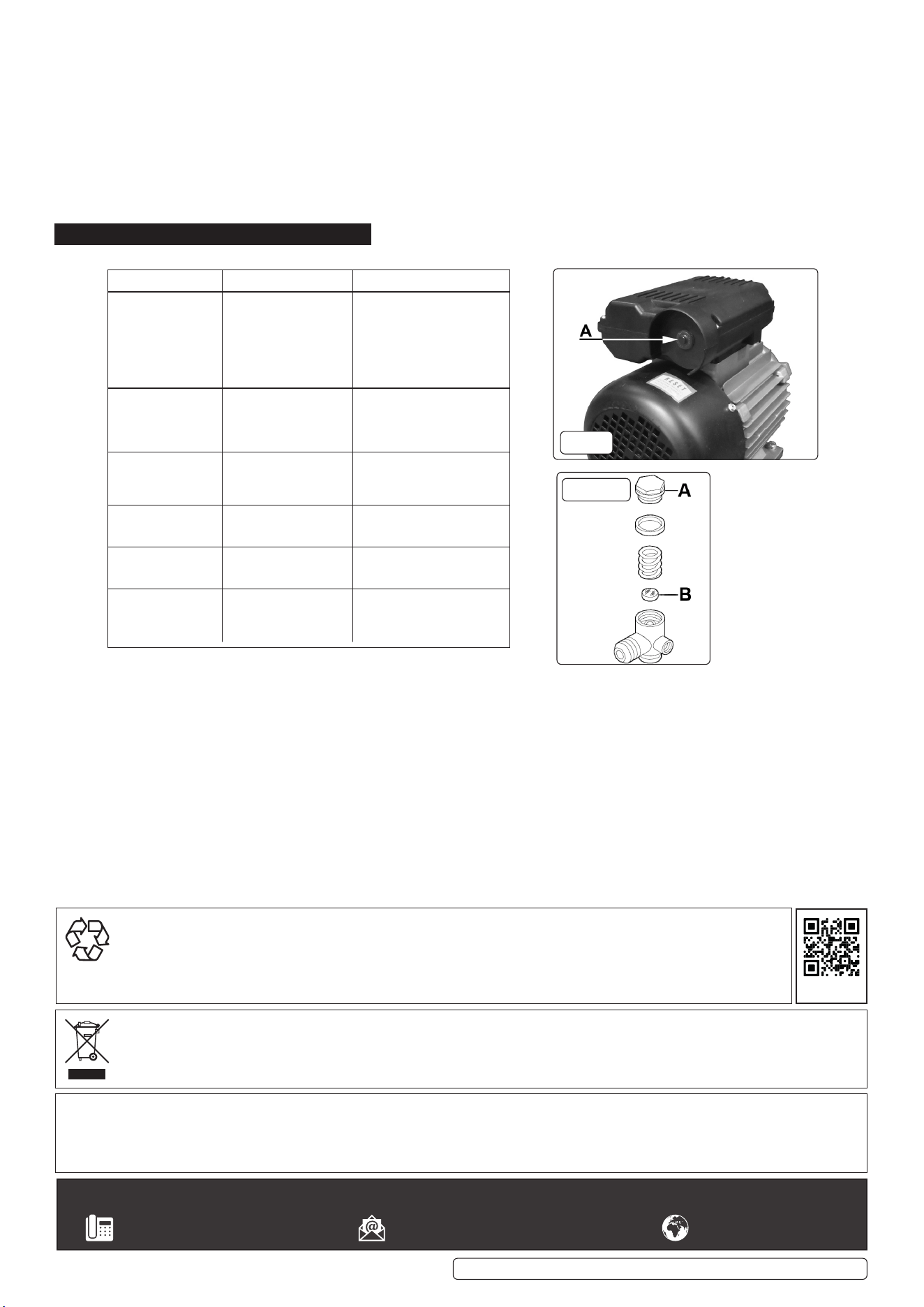
5.1.6. The motor of the compressor is fitted with a thermal breaker located in the housing on top of the motor. The manual resetting button is
located in the end of the housing as shown in fig.10A. When the breaker is tripped, wait for a few minutes and then press the reset button.
5.1.7. On Models SAC1503B and SAC1103B, the output pressure is regulated by the pressure regulator (fig.6.2). Turn the knob clockwise
to increase pressure and anti-clockwise to reduce it. Lock knob in position at required pressure with locking ring. To determine the correct
working pressure for any piece of equipment check the corresponding manual. When the compressor is not being used, set the regulated
pressure to zero so as to avoid damaging the pressure regulator.
NOTE:
a) If the motor does not cut in and out, but runs continuously when using an air appliance, the capacity of the compressor may be too
small for the equipment or tool.
b)The gauge (figs.6.5 and 7.5) indicates the pressure inside the main tank, NOT the pressure supplied to the air equipment.
Should the pressure in the main tank exceed the pre-set switch maximum, the safety valve will activate.
WARNING! For this reason DO NOT tamper with, or adjust, the switch or safety valve.
6. MAINTENANCE
6.1. In order to keep the compressor in good working condition, periodic maintenance is essential.
IMPORTANT! Failure to carry out maintenance tasks may invalidate the warranty on your compressor.
WARNING!Beforeperforminganymaintenanceoperation,switchothecompressor,disconnectfromelectricitysupplyandreleaseall
air from the tank (except for 6.3.a)
6.2. Operations to be carried out after the first 50 working hours:
a) Checkthatallbolts/nutsaretight,particularlythoseretainingthecrankcaseandcylinderhead.
b) Replace the lubricating oil - see para 6.5.
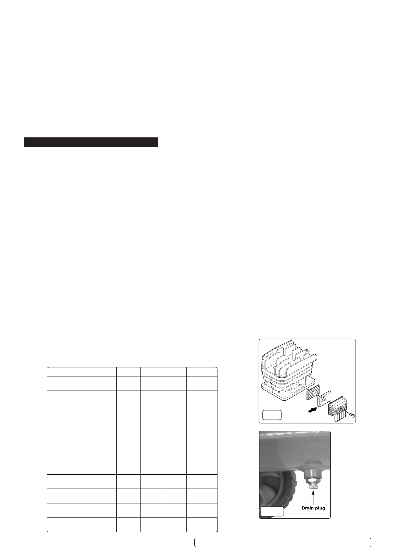
6.3. Operations to be carried out weekly:
a) Drain condensation by opening the valve located under the tank (fig.9). Place a container under the valve and open the valve
by turning anti-clockwise.
WARNING! Takecareifthereisstillpressureinsidethecylinderaswatercouldowoutwithconsiderableforce.Recommended
pressure 1 - 2bar max.
b) Check oil level and, if necessary, top up.
6.4. Operations to be carried out every 50 hours (or more frequently, if the compressor operates in a very dusty atmosphere):
a) Removetheairfilterelement(fig.8).Usingstoredairfromthecompressor’stank,cleanthefilterwithcompressedair.(Wear
eye protection and DO NOT direct air towards the body or hands). DO NOT operate the compressor without the filter as foreign bodies
or dust could seriously damage the pump. Replace the filter element and air filter housing.
b) Check for oil leaks.
6.5. Operations to be carried out every 100 hours:
a)Check the automatic cut-out at max. pressure and the automatic cut-in at 2bar below.
6.6. Operations to be carried out every 400 hours:
a) Replace the lubricating oil. For oil specifications see 6.8.
Removethefiller/breatherplug(seefig.4)thenremoveoildrainplug,drainingtheoilintoacontainer.Drainwhenthecompressorishot
so that the oil drains rapidly and completely. Incline compressor to ensure complete drainage. Replace oil drain plug and refill through
thefiller/breatheraperture.DO NOT overfill. Replace plug.
WARNING!NevermixdierentoilsandDO NOTusenon-detergent/lowqualityoilsasthecompressormaybedamaged.
WARNING! Dispose of waste oil only in accordance with local authority requirements.
b) Replace air filter. (See fig.8)
c) Check all tube fittings and electrical connections.
d) Inspect pressure tank inside and out for damage or corrosion.
6.7. Maintenance Schedule
Maintenance Operations Weekly 50hrs 100hrs 400 hrs
Drain condensation
•
Check oil level
•
Clean intake filter
•
Check for oil leaks
•
Replace oil
•
Check cut-out
•
General cleaning of
compressor
•
Replace air filter
•
Check tube fittings and
electrical connections
•
Internal & external
inspection of tank
•
Check and adjust belt
tension
•
fig.9
fig.8
SAC1503B, SAC1103B, SAC1153B, SAC1203B Issue:5(H,F)16/05/23
Original Language Version
© Jack Sealey Limited
6.8. Recommended oils
Syntheticoilsuitablefortemperaturesrangingfrom-5°Cto45°C:Viscosity5W50.WeDO NOT recommend using mineral oil in these
compressors.
Part No. Qty. Description
FSO1 1L x 12 Compressor oil fully synthetic
FSO1S 1L x 1 Compressor oil fully synthetic
FSO5 5L x 1 Compressor oil fully synthetic
IMPORTANT WARNING-Aircontaminantstakenintothecompressorwillaectoptimumperformance.Example:Bodyller
dustorpaintoverspraywillclogthepumpintakelterandmaycauseinternaldamagetopump/motorcomponents.Pleasenote
that any parts damaged by any type of contamination will not be covered by warranty.
7. TROUBLE SHOOTING
Fault Cause Remedy
Pressure drop in the
tank.
Air leaks at
connections.
Run compressor to max.
pressure, switch off.
Brush soap solution over
connections and look for
bubbles. Tighten connections
showing leaks. If problem
persists contact Authorised
Service Agent.
Pressure switch
valve leaks when
compressor is idle.
Non-return valve seal
defective.
Discharge all tank pressure.
Referring to fig.11, unscrew
valve cap 'A'. Clean rubber
disc 'B' and its seat. Refit all
parts accurately.
Compressor stops
and does not restart.
Power failure.
Motor failure.
Check electricity supply and
fuse.
Contact Authorised Service
Agent.
Compressor does
not stop at max
pressure.
Pressure switch fault. Contact Authorised Service
Agent.
Compressor does
not reach max
pressure.
Filter clogged.
Head gasket or valve
fault.
Replace filter element.
Contact Authorised Service
Agent.
Compressor noisy
with metallic knock.
Low oil level.
Bearing or piston
damage.
Turn off and top up oil
immediately.
Contact Authorised Service
Agent.
fig.10
fig.11
Sealey Group, Kempson Way, Suffolk Business Park, Bury St Edmunds, Suffolk. IP32 7AR
01284 757500 sales@sealey.co.uk www.sealey.co.uk
ENVIRONMENT PROTECTION
Recycle unwanted materials instead of disposing of them as waste. All tools, accessories and packaging should be sorted,
taken to a recycling centre and disposed of in a manner which is compatible with the environment. When the product
becomes completely unserviceable and requires disposal, drain any fluids (if applicable) into approved containers and
dispose of the product and fluids according to local regulations.
Note: It is our policy to continually improve products and as such we reserve the right to alter data, specifications and component parts without prior
notice.
Important: No Liability is accepted for incorrect use of this product.
Warranty: Guarantee is 12 months from purchase date, proof of which is required for any claim.
WEEE REGULATIONS
Dispose of this product at the end of its working life in compliance with the EU Directive on Waste Electrical and Electronic Equipment
(WEEE). When the product is no longer required, it must be disposed of in an environmentally protective way. Contact your local solid
waste authority for recycling information.
REGISTER YOUR
PURCHASE HERE
SAC1503B, SAC1103B, SAC1153B, SAC1203B Issue:5(H,F)16/05/23