
24L DIRECT DRIVE AIR COMPRESSOR 2HP/
4PC AIR ACCESSORY KIT
MODEL NO: SAC2420E.V3 / SAC2420EPK.V2
Thank you for purchasing a Sealey product. Manufactured to a high standard, this product will, if used according to these instructions,
and properly maintained, give you years of trouble free performance.
IMPORTANT: PLEASE READ THESE INSTRUCTIONS CAREFULLY. NOTE THE SAFE OPERATIONAL REQUIREMENTS, WARNINGS & CAUTIONS. USE
THE PRODUCT CORRECTLY AND WITH CARE FOR THE PURPOSE FOR WHICH IT IS INTENDED. FAILURE TO DO SO MAY CAUSE DAMAGE AND/OR
PERSONAL INJURY AND WILL INVALIDATE THE WARRANTY. KEEP THESE INSTRUCTIONS SAFE FOR FUTURE USE.
1. SAFETY
1.1. ELECTRICAL SAFETY
WARNING! It is the user’s responsibility to check the following:
9 Check all electrical equipment and appliances to ensure that they are safe before using. Inspect power supply leads, plugs
and all electrical connections for wear and damage. Sealey recommend that an RCD (Residual Current Device) is used with
all electrical products.
Electrical safety information. It is important that the following information is read and understood:
9 Ensure that the insulation on all cables and on the appliance is safe before connecting it to the power supply.
9 Regularly inspect power supply cables and plugs for wear or damage and check all connections to ensure that they are secure.
Important: Ensure that the voltage rating on the appliance suits the power supply to be used and that the plug is tted with the correct fuse.
8 DO NOT pull or carry the appliance by the power cable.
8 DO NOT pull the plug from the socket by the cable.
8 DO NOT use worn or damaged cables, plugs or connectors. Ensure that any faulty item is repaired or is replaced immediately
by a qualied electrician.
If the cable or plug is damaged during use, switch off the electricity supply and remove from use.
Ensure that repairs are carried out by a qualied electrician.
1.2. GENERAL SAFETY
9 Familiarise yourself with the application and limitations of the compressor.
9 Ensure the compressor is in good order/condition before use. If in doubt DO NOT use the unit and contact an electrician/service agent.
WARNING! Compressor must only be serviced by an authorised agent. DO NOT tamper with, or attempt to adjust, pressure switch or
safety valve.
9 Before moving, or maintaining the compressor ensure it is unplugged from the mains supply and that the air tank pressure has been vented.
9 Maintain the compressor in good condition and replace any damaged or worn parts. Use genuine parts only. Unauthorised parts may be
dangerous and will invalidate your warranty.
9 Read the instructions relating to any accessory to be used with this compressor. Ensure the safe working pressure of any air appliance
used exceeds compressors output pressure. If using a spray gun, check that the area selected for spraying is provided with an air change
system/ventilation.
9 Ensure the air supply valve is turned off before disconnecting the air supply hose.
9 To move a transportable compressor use the handle only. Lift the compressor so that the front leg gives enough clearance for manoeuvring
but maintain unit’s centre of gravity in front of the wheels. DO NOT attempt to lift or move the compressor by any other means.
9 Use the compressor in a well ventilated area and ensure it is placed on a firm surface.
9 Keep tools and other items away from the compressor when it is in use, and keep area clean and clear of unnecessary items.
9 Ensure the air hose is not tangled, twisted or pinched.
9 Keep children and unauthorised persons away from the working area.
8 DO NOT dis-assemble compressor for any reason. The unit must be checked by qualified personnel only.
8 DO NOT use the compressor outdoors, or in damp, or wet, locations.
8 DO NOT operate within the vicinity of flammable liquids, gases or solids.
8 DO NOT touch compressor cylinder, cylinder head or pipe from head to tank as these may be hot.
8 DO NOT use this product to perform a task for which it has not been designed.
8 DO NOT deface the certification plate attached to the compressor tank.
8 DO NOT cover the compressor or restrict air flow around the unit whilst operating.
▲ DANGER! DO NOT direct the output jet of air towards people or animals.
8 DO NOT operate the compressor without an air filter.
8 DO NOT allow anyone to operate the compressor unless they have received full instructions.
WARNING! The air tank is a pressure vessel and the following safety measures apply:
8 DO NOT tamper with the safety valve, DO NOT modify or alter the tank in any way and DO NOT strap anything to the tank.
8 DO NOT subject the tank to impact, vibration or to heat and DO NOT allow contact with abrasives or corrosives.
9 Drain condensation from tank daily and inspect inside walls for corrosion every three months and have a detailed tank inspection carried
out annually. The tank shell must not fall below the certified thickness at any point.
WARNING! If an electrical fuse blows, ensure it is replaced with an identical fuse type and rating.
9 When not in use, store the compressor carefully in a safe, dry, childproof location.
9 When the compressor is not in use it should be switched off, disconnected from the mains supply and the air drained from the tank.
Refer to
instruction
manual
Wear eye
protection
Wear ear
protection
Warning:
Hot surface
Warning:
Automatic
start-up
Warning:
Electricity
Ensure oil level
is correct
before first use
DO NOT open
the air cock
before an air
hose is attached
Indoor
use only
Original Language Version
© Jack Sealey Limited
SAC2420E.V3, SAC2420EPK.V2 Issue 2 (H,3,F) 25/03/24
8 DO NOT carry out any welding operations on any pressurised parts of
the vessel.
1.3. INSPECTION OF PRESSURE TANK BOTH INTERNAL AND
EXTERNAL
1.3.1. Under the Pressure Systems Safety Regulations 2000 it is the
responsibility of the owner of the compressor to initiate a system of
inspection that both denes the frequency of the inspection and appoints
a person who has specic responsibility for carrying out the inspection.
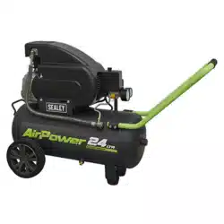
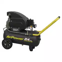
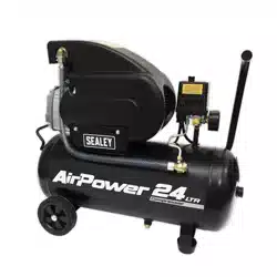
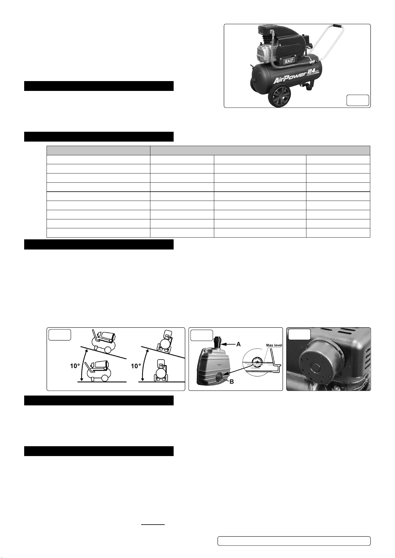
2. INTRODUCTION
Aluminium cylinder head with cast iron cylinder gives added resistance
to wear. Suitable for general-purpose workshop applications. Pump head
directly coupled to heavy-duty induction motor for reliable and quiet
operation. Precision welded receiver tank manufactured to meet Pressure Vessel Directive. Fitted with fully automatic pressure cut-out
switch and twin gauges displaying tank and working pressures. Fitted with 3-pin plug.
3. SPECIFICATION
Model No: SAC2420E.V3
Air Displacement cfm(L/min): 6.8(193) Outlet: Quick Release Coupling
Fuse Rating: 13A Phase: 1ph
Maximum Free Air Delivery cfm(L/min): 4.6(130) Plug Type: 3-Pin
Maximum Pressure: 116psi(8bar) Power Supply Cable Length: 1.8m
Minimum Rated Supply: 13A Receiver Capacity: 24L
Motor Output: 2hp Recommended Oil: ISO 100
Nett Weight: 26.5kg Size (W x D x H): 600 x 290 x 585mm
Noise Level: 96dB(A) Supply: 230V/13A
Oil Capacity: 0.27L
4. ASSEMBLY
4.1. Remove compressor from packaging and inspect for any shortages or damage. If anything is found to be missing or damaged, contact
your supplier.
4.2. Confirm that the mains voltage corresponds with the voltage shown on the compressor data plate.
4.3. The compressor should be installed on a flat surface, or one that does not exceed 10° either transversely or longitudinally, (see fig.2) and
should be in a position that allows good air circulation around the unit.
4.4. The compressor is supplied without oil in it. The oil is in a separate container. Remove the transit plug from the oil filler aperture, pour oil
into the aperture until it has reached the correct level on the sight (fig.3). Fit the oil filler/breather supplied into the aperture.
4.5. Ensure that the air vent in the oil filler/breather is free from debris. If the air vent is blocked, pressure can build up in the crankcase
causing damage to the compressor and possible personal injury.
4.6. If it is not already fitted, screw the air filter holder into the inlet port (fig.4).
FIG.2
FIG.3
FIG.4
5. TOOL SELECTION
IMPORTANT Take care when selecting tools for use with the compressor. Air tool manufacturers normally express the volume of
air required to operate a tool in cubic feet per minute (cfm). This refers to free air delivered by the compressor (‘air out’) which varies
according to the pressure setting. DO NOT confuse this with the compressor displacement which is the air taken in by the compressor (‘air
in’). ‘Air out’ is always less than ‘air in’ - due to losses within the compressor - and so it is important that, before choosing equipment, you
study the ‘Free Air Delivery’ figures shown in the Specification Chart.
6. OPERATION
WARNING! Ensure that you have read, understood and applied Section 1 Safety Instructions.
6.1. Make sure that the main switch (fig.5.1) is ‘OFF’ (down).
6.2. Check the oil level by looking through the sight glass (fig.3).
6.3. Ensure that the tank drain valve is closed (fig.1).
6.4. Connect the air tool required to the compressor via an air line connected to the air outlet.
6.5. Plug the mains plug into the mains supply and start the compressor by pulling up the main switch (fig.5.1).
6.6. Allow the pressure in the tank to rise to the maximum at which point the compressor will automatically cut out. Tank pressure is shown on
the larger gauge (fig.5.6).
6.7. Begin to gradually open the regulator by turning the knob clockwise (fig.5.2) until the small gauge registers the required operating pressure
specified for the tool to be used. Always adjust up to the required pressure rather than down from a pressure. The required setting, once
achieved, can be locked by screwing the locking ring (fig.5.3) up tight underneath the adjusting knob.
Original Language Version
© Jack Sealey Limited
SAC2420E.V3, SAC2420EPK.V2 Issue 2 (H,3,F) 25/03/24
FIG.1
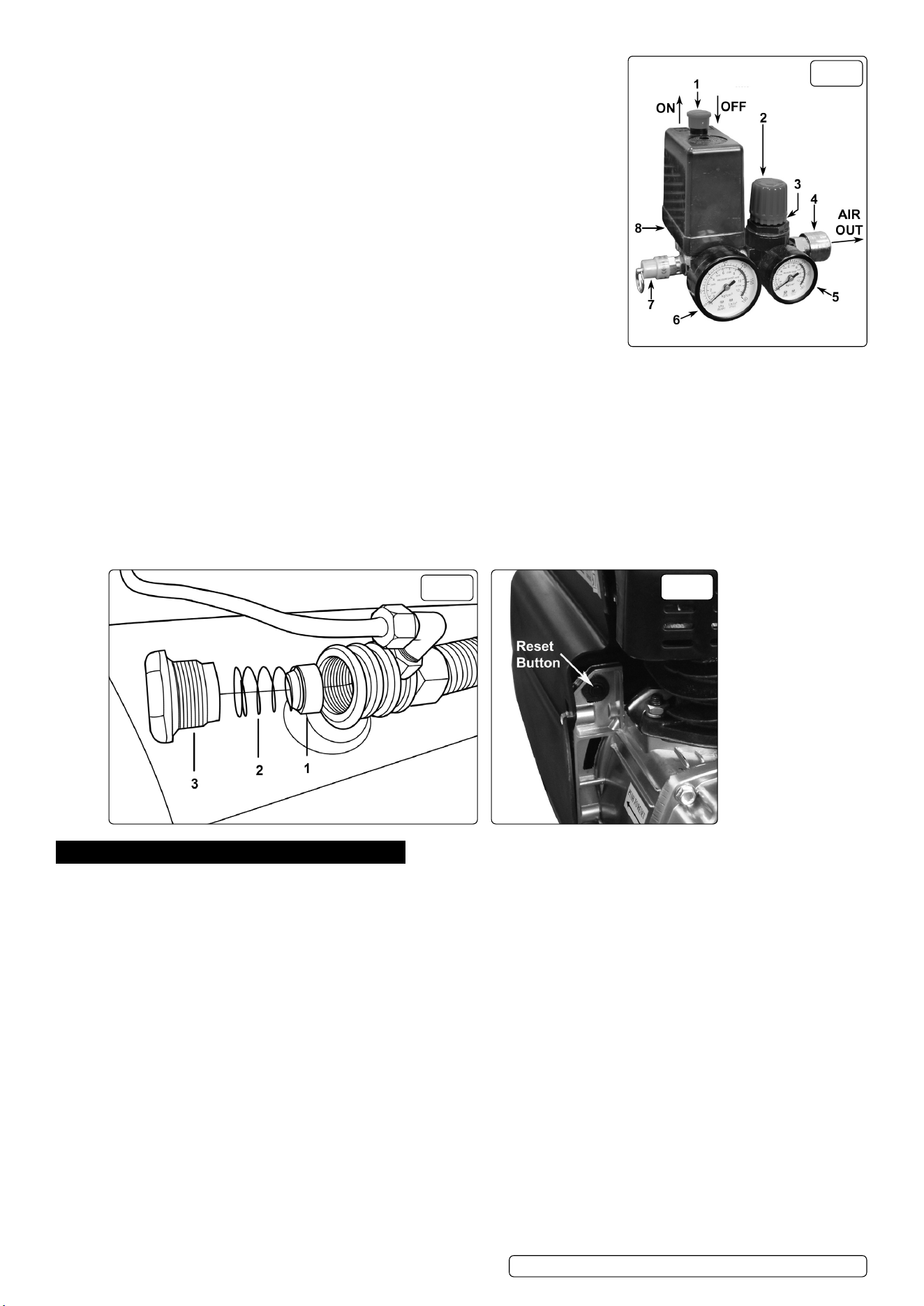
6.8. You can now begin to use the tool. The compressor will operate automatically cutting in and
out as required to restore the air pressure in the tank. The pressure switch (fig.5.8) stops the
motor when the maximum tank pressure is reached and restarts it when pressure falls below
the minimum threshold - approx. 2 bar (29psi) less than the maximum pressure.
NOTE: A). If the motor does not cut in and out, but runs continuously when using an air
appliance, the capacity of the compressor may be too small for the appliance.
B). The main gauge (fig.5.6) indicates the pressure inside the main tank, NOT the pressure
supplied to the air equipment, which is shown on the smaller gauge (fig.5.5). Should the
pressure in the main tank exceed the pre-set switch (fig.5) maximum, the safety valve
(fig.5.7) will activate.
WARNING! For this reason DO NOT tamper with, or adjust, the switch or the safety
valve.
6.9. When the compressor is not being used set the regulated pressure to zero so as to avoid
damaging the pressure regulator.
6.10. To stop the compressor press down the main switch (fig.5.1). When the compressor stops
there will be a whistling sound as compressed air is vented from the compressor head. DO
NOT, other than in an emergency, stop the compressor by switching off the mains power,
or by pulling the plug out, as the pressure relief will not then occur and motor damage may
result upon restart.
6.11. When you have finished using the compressor unplug the unit from the mains power supply.
6.12. Set the outlet pressure on the regulator to zero.
6.13. Remove the air line and air tool.
6.14. The tank must now be drained. This will release the air left in the tank and drain away condensation that may have formed within the tank.
Choose a suitable location for this operation and/or make provision to collect the condensation. Wear ear and eye protection. Open
the tank drain valve (fig.1) slowly, allowing air and moisture to bleed from the tank. After bleeding, close the drain valve to prevent debris
building up in the valve.
WARNING! Water that is allowed to remain in the tank during storage will corrode and weaken the air tank, which could cause the tank to
rupture. To avoid serious injury, drain the tank on a daily basis.
6.15. SAFETY FEATURES
Thermal cut out: If the unit overheats the thermal cut out will operate and shut the unit down. Allow the unit to cool down then press the
reset button, located just inside the pump cover (fig.7).
FIG.6
FIG.7
7. MAINTENANCE
WARNING! Before performing any maintenance operation, switch off the compressor, disconnect from electricity supply and release all air
from the tank. In order to keep the compressor in good working condition, periodical maintenance is essential.
7.1. After the first 50 working hours replace the lubricating oil - see item 7.4.
7.2. OPERATIONS TO BE CARRIED OUT DAILY:
7.2.1. Drain condensation, place a container under the valve and open the valve by turning anti-clockwise (fig.1). Retighten the valve.
7.2.2. Check that all nuts and bolts are tight, particularly those retaining the crankcase and cylinder head.
7.3. OPERATIONS TO BE CARRIED OUT EVERY 100 HOURS: (or more frequently, if the compressor operates in a very dusty atmosphere).
7.3.1. Check oil level and, if necessary, top it up.
7.3.2. Remove the air filter element by unscrewing the filter holder (fig.4) and prising open the holder. Clean it by blowing through with an air line
at low pressure, from the clean side. Alternatively, wash it in soapy water, rinse and dry. DO NOT operate the compressor without the filter
as foreign bodies or dust could seriously damage the pump.
7.3.3. Check for oil leaks.
7.4. OPERATIONS TO BE CARRIED OUT EVERY 200 HOURS:
7.4.1. Replace the lubricating oil. Remove the oil filler/breather and unscrew the drain bolt (fig.3B), drain the oil into a suitable container. Drain
when the compressor is hot so that the oil drains rapidly and completely. Incline the compressor to ensure complete drainage. Replace the
drain bolt and refill with fresh oil through the filler aperture. DO NOT overfill.
7.4.2. Replace oil filler/breather (fig.3).
7.5. RECOMMENDED OIL
7.5.1. Suitable for room temperatures ranging from +5ºC to +25ºC: SEALEY CPO or equivalent SAE 40 compressor oil.
7.5.2. Room temperature below +5ºC: SAE 20 compressor oil
WARNING! Never mix different oils and DO NOT use non-detergent/low quality oils as the compressor may be damaged.
7.5.3. Dispose of waste oil only in accordance with local authority requirements.
7.5.4. Check the automatic cut-out at maximum pressure and the automatic cut-in at 2 bar below that.
FIG.5
Original Language Version
© Jack Sealey Limited
SAC2420E.V3, SAC2420EPK.V2 Issue 2 (H,3,F) 25/03/24

7.6. OPERATIONS TO BE CARRIED OUT EVERY 500 HOURS:
7.6.1. Replace air filter.
7.6.2. Check all tube fittings and electrical connections.
7.6.3. IMPORTANT! Failure to carry out maintenance tasks may invalidate the warranty on your compressor.
WARNING - Air contaminants taken into the compressor will affect optimum performance e.g. body ller dust or paint overspray will
clog the pump intake lter and may cause internal damage to pump/motor components.
NOTE: Any parts damaged by any type of contamination will not be covered by warranty.
7.7. INSPECTION OF PRESSURE TANK BOTH INSIDE AND OUT
7.7.1. Under the PRESSURE SYSTEMS SAFETY REGULATIONS 2000 it is the responsibility of the owner of the compressor to initiate a
system of inspection that both defines the frequency of the inspection and appoints a person who has specific responsibility for carrying
out the inspection.
8. tTROUBLESHOOTING
FAULT CAUSE REMEDY
1A) Pressure drop in the tank. Air leaks at connections. Run compressor to max. pressure, switch off
Brush soap solution over connections and look
for bubbles. Tighten connections showing leaks.
If problem persists contact Authorised Service
Agent.
1B) Pressure drop in the tank. Air leaks from safety valve. Operate the safety valve manually by pulling on
the ring. If valve continues to leak when in the
closed position it should be replaced.
1C) Pressure drop in the tank. Air leaks from cylinder head gasket. Check tightness of head bolts. If leak continues
contact Authorised Service Agent.
2) Pressure switch valve leaks when
compressor is idle.
Non-return valve seal defective. Empty the air tank. Referring to fig.6, remove the
non-return valve cap (3), spring (2) and seal (1).
Clean the seal and its seat, or if necessary
replace the seal and refit.
3) Air leaks from tank body or tank welds. Internal corrosion caused by infrequent tank
draining or non permitted modifications to tank.
Tank could rupture or explode. Cannot be
repaired.DISCONTINUE USE IMMEDIATELY.
4A) Motor stops and will not restart. Thermal cut out has operated. Allow unit to cool for 30 minutes then press
reset button (fig.7)
4B) Motor stops and will not restart. Supply fuse has tripped. Reset fuse and restart unit. If repeated tripping
occurs, replace the check valve or contact
Authorised Service Agent.
5) Compressor stops and does not restart. Motor failure. Contact Authorised Service Agent.
6A) Compressor does not stop at max.
pressure.
Pressure switch fault. Contact Authorised Service Agent.
6B) Compressor does not stop at max.
pressure.
Filter clogged.
Head gasket or valve fault.
Replace filter element.
Contact Authorised Service Agent.
7) Compressor noisy with metallic knock. Bearing or piston damage. Contact Authorised Service Agent.
8) Excessive moisture in discharged air. High humidity environment. Drain tank after each use.
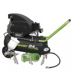
4 PC AIR ACCESSORY KIT
SUPPLIED WITH MODEL NO: SAC2420EPK.V2
9. SPRAY GUN SAFETY
WARNING! Disconnect the spray gun from the air supply before changing accessories, servicing or performing any maintenance.
9 Familiarise yourself with this products application and limitations, as well as the specific potential hazards peculiar to the spray gun.
Paint cup remains pressurised after gun is disconnected from air line.
8 DO NOT pull the trigger, but release the pressure by gently opening cup.
9 Maintain the spray gun in good condition (use an authorised service agent).
9 Replace or repair damaged parts. Use recommended parts only. Non authorised parts may be dangerous and will invalidate the warranty.
9 Locate the spray gun in an adequate working area for its function, keep area clean and tidy and free from unrelated materials, and ensure
there is adequate ventilation and lighting.
9 Keep the spray gun clean for best and safest performance.
9 Wear approved respiratory protection and safety eye goggles.
9 Remove ill fitting clothing. Remove ties, watches, rings, and other loose jewellery, and tie back long hair.
9 Keep children and unauthorised persons away from the working area.
9 Avoid unintentional operation.
8 DO NOT point spray gun at yourself, at other persons or animals.
8 DO NOT carry the by the air hose, or pull the hose from the air supply.
8 DO NOT use the spray gun for any purpose other than for which it is designed.
8 DO NOT allow untrained persons to operate the spray gun.
8 DO NOT get the spray gun wet or use in damp or wet locations or areas where there is condensation.
8 DO NOT operate gun if any parts are missing or damaged as this may cause failure or personal injury.
8 DO NOT direct air from the air hose at yourself or others.
9 When not in use switch the spray gun off, and disconnect from the air supply.
Original Language Version
© Jack Sealey Limited
SAC2420E.V3, SAC2420EPK.V2 Issue 2 (H,3,F) 25/03/24
10. TYRE INFLATOR SAFETY
9 Disconnect the gauge from the air supply before changing accessories, servicing or performing any maintenance.
9 Maintain the gauge in good condition (use an authorised service agent), and keep the gauge clean for best and safest performance.
9 Replace or repair damaged parts. Use recommended parts only. Unauthorised parts may be dangerous and will invalidate the warranty.
9 Locate gauge in a suitable work area, keep area clean and tidy and free from unrelated materials and ensure there is adequate lighting.
9 Keep children and unauthorised persons away from the work area.
8 DO NOT direct gauge outlet at yourself or at other persons or animals.
8 DO NOT carry by the hose, or yank the hose from the air supply.
8 DO NOT use the gauge for a task which it is not designed to perform.
8 DO NOT operate the gauge when you are tired or under the influence of alcohol, drugs or intoxicating medication.
8 DO NOT operate gauge if parts are missing or the gauge is damaged, as this may cause failure and/or personal injury.
11. AIR GUN SAFETY
WARNING! Disconnect blow gun from the air supply before changing accessories, servicing or performing any maintenance.
9 De-pressurise the blow gun before removing air hose from the gun.
9 Maintain the blow gun in good condition (use an authorised service agent).
9 Replace or repair damaged parts. Use genuine parts only. Non genuine parts may be dangerous and will invalidate the warranty.
9 Keep the work area clean, uncluttered and ensure there is adequate lighting.
9 Only use the blow gun for the purpose of blowing compressed air.
WARNING! Always wear approved eye or face protection when operating the blow gun. Use a face or dust mask if dust is generated.
Wear appropriate protective clothing.
9 Maintain correct balance and footing. Ensure the floor is not slippery and wear non slip shoes.
9 Remove ill fitting clothes, ties, watches, rings, other loose jewellery, and contain/tie back long hair.
9 Keep children and unauthorised persons away from the working area.
9 Secure non stable work piece with a clamp, vice or other adequate holding device.
9 Avoid unintentional starting.
WARNING! air pressure should not exceed 90psi.
9 Keep air hose away from heat, oil and sharp edges. Check air hose for wear before each use, and ensure that all connections are secure.
8 DO NOT use the blow gun for any purpose other than for which it is designed.
8 DO NOT operate blow gun if any parts are damaged or missing as may cause failure or personal injury.
8 DO NOT carry the by the hose, or yank the hose from the air supply.
8 DO NOT allow untrained persons to operate the blow gun.
8 DO NOT operate blow gun when you are tired, under influence of alcohol, drugs or intoxicating medication.
8 DO NOT leave the blow gun operating whilst unattended.
8 DO NOT direct air from the blow gun at yourself, others or animals.
9 When not in use disconnect from the blow supply and store in a safe, dry, child proof area.
12. INTRODUCTION
Kit contains: Gravity feed spray gun, tyre inator, air blow gun, 5m air hose 1/4”BSP.
13. SPECIFICATION
Rated air pressure for all tools in the Air kit ............ 90psi
Max. working pressure of PE Hose ........................90bar
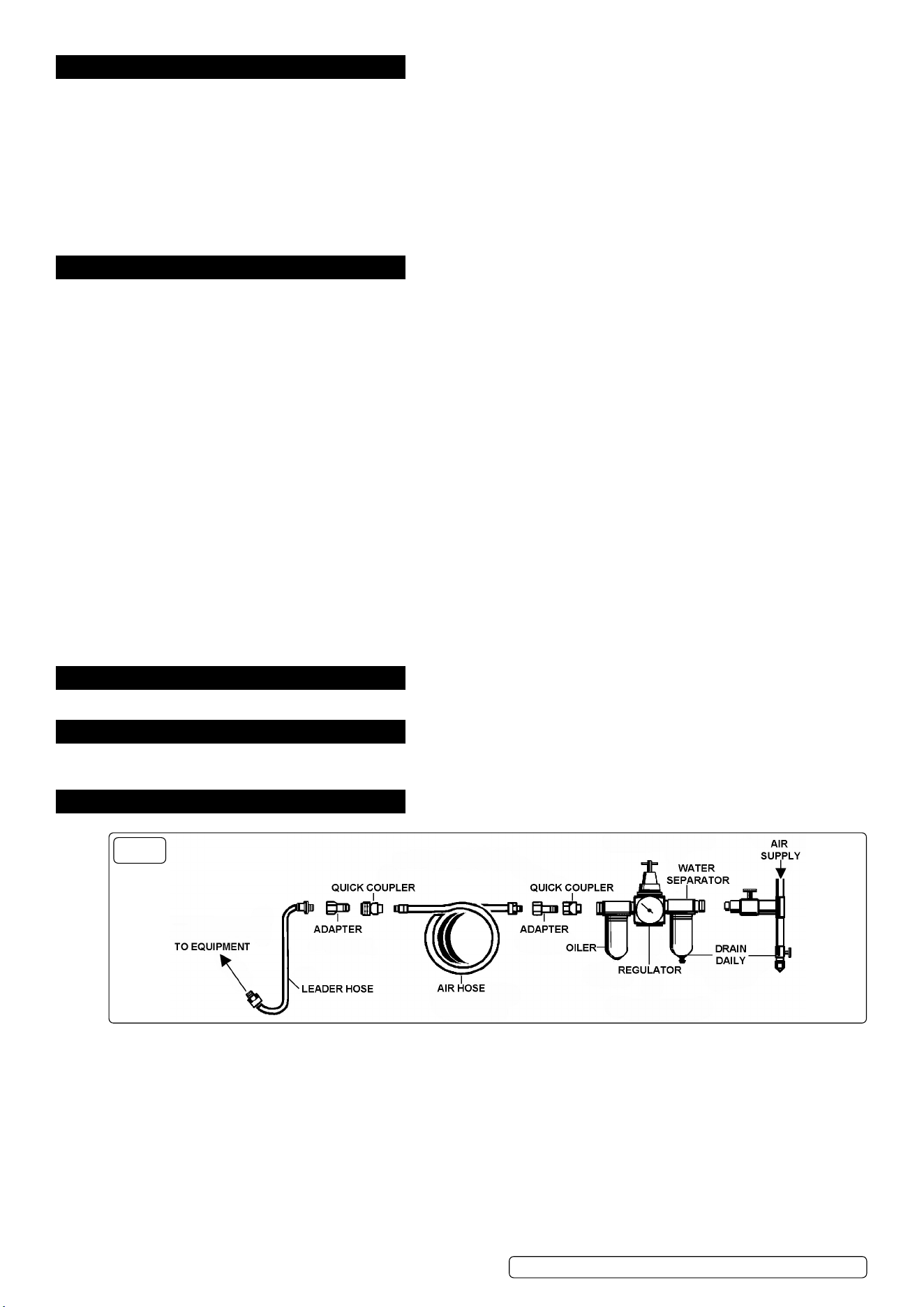
14. AIR SUPPLY
FIG.8
14.1. Recommended hook-up g.8.
14.1.1. Ensure tool’s air valve (or trigger) is in the off position before connecting to the air supply.
WARNING! Ensure the air supply is clean and does not exceed specication (above) while operating the tool. Too high an air pressure
and/or unclean air will shorten the product life due to excessive wear, and may be dangerous causing damage and/or personal
injury.
14.1.2. Drain the air tank daily. Water in the air line will ruin the paint nish and damage the tool.
14.1.3. Clean air inlet lter weekly.
14.1.4. Line pressure should be increased to compensate for unusually long air hoses (over 8 metres). The minimum hose diameter should be
1/4” I.D. and ttings must have the same inside dimensions.
14.1.5. Keep hose away from heat, oil and sharp edges. Check hose for wear, and make certain that all connections are secure.
14.2. COUPLINGS
Vibration may cause failure if a quick change coupling is connected directly to the tool. To overcome this, connect a leader hose. A
quick change coupling may then be used to connect the leader hose to the air line recoil hose (g.8).
Original Language Version
© Jack Sealey Limited
SAC2420E.V3, SAC2420EPK.V2 Issue 2 (H,3,F) 25/03/24
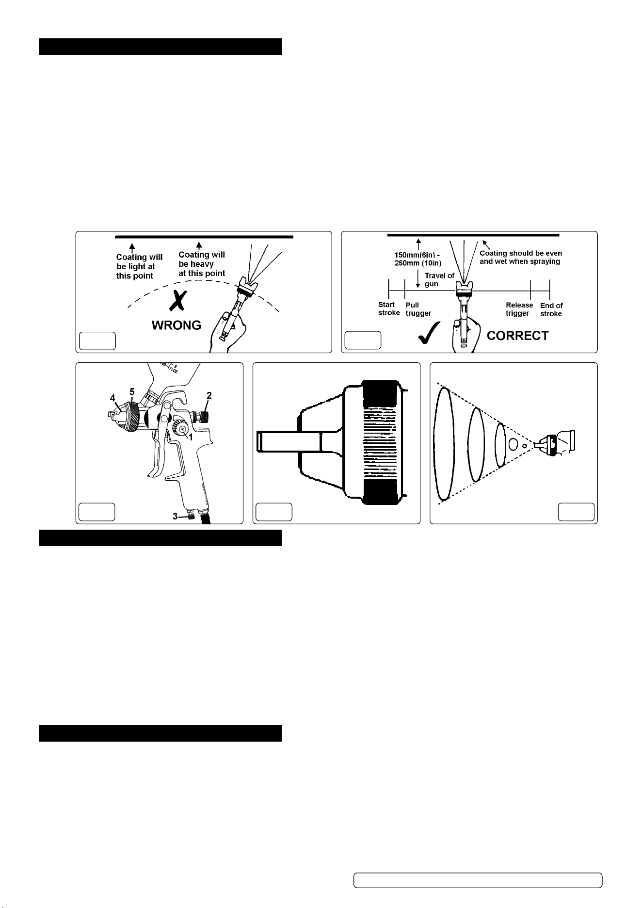
15. SPRAY GUN OPERATION
15.1. For best results, the gun should be held perpendicular to the surface being sprayed and moved parallel to it. Start the stroke before
squeezing the trigger and release the trigger before nishing the stroke. This will enable accurate control of the gun and material refer
to g’s 9 & 10 below.
15.2. Spray from a distance of about 6 to 10 inches (150 to 250mm) depending on the material and the atomizing pressure. The material
deposited should always be even and wet. Each stroke must overlap the preceding stroke to obtain a uniform nish. To reduce over-
spray and obtain maximum efciency, spray with the lowest possible atomizing air pressure.
15.3. Controlling the fan spray and the uid.
a) Use the needle (paint) adjustment knob (g.11.2) to adjust the amount of paint ow.
b) The atomizing air ow is controlled by the control knob (g.11.1).
c) The volume of air input is controlled by the adjustment knob (g.11.3).
d) As width of spray is increased more material must pass through the gun to obtain the same coverage on the increased area.
e) Turn the air nozzle (g.11.4) to achieve a horizontal or vertical fan spray. Lock the nozzle with retaining ring (g.11.5).
The spray pattern of the gun is variable from round to at with all patterns in between. In normal operation, the wings on the
nozzle are horizontal (g.12). This provides a vertical fan-shaped pattern which gives maximum, uniform and even coverage
when moving the gun back and forth, parallel to the work surface (g.13).
FIG.10
FIG.9
FIG.12FIG.11 FIG.13
16. SPRAYGUN MAINTENANCE
FOR OPTIMUM PERFORMANCE IT IS IMPORTANT TO ENSURE THE SPRAY GUN IS CORRECTLY CLEANED AFTER EACH USE.
Disconnect from the air supply before attempting any cleaning or maintenance.
16.1. CLEANING THE GUN
16.1.1. Flush the gun through with clean solvent.
16.1.2. Use a bristle brush and solvent to wash off accumulated paint.
16.1.3. Clean the air nozzle using a brush. Blow clean with air. Handle all nozzles carefully and do not make any alterations in the gun.
16.1.4. Wipe the outside of the gun with a dampened solvent rag.
16.1.5. If there is a need to probe the holes in the nozzles, ensure a tool that is softer than brass is utilised, under no circumstances use a
metal tool, as the slightest amount of damage will adversely affect the spray pattern.
16.1.6. Adjust the uid needle valve so that when the gun is triggered, air ow occurs before uid ow.
16.2. MAINTENANCE
16.2.1. Take care when re-assembling. Screw parts hand tight to avoid cross-threading. If a part cannot easily be turned by hand, check that it
is the correct part, or unscrew it, realign and retry. DO NOT use excessive force when re-assembling.
16.2.2. When changing the nozzle size, ensure the complete nozzle set is tted. This consists of air cap, uid nozzle and paint needle. Insert
the uid nozzle before paint needle.
17. TYRE INFLATOR OPERATION
17.1. ATTACH ADAPTOR TO VALVE
Push and hold the connector onto the tyre valve, squeeze the thumb clip on the connector, push the connector onto the tyre valve and
release the clip. The connector will now be locked in place.
17.2. TO INFLATE
Momentarily depress the operation lever fully, then release to display tyre pressure. When reading the pressure, hold the gauge “at”
with respect to the eye to minimise error. Fully depress operation lever for an appropriate period. Avoid over inflation, release lever
frequently to check the pressure.
17.3. TO DEFLATE
Depress lever half-way (until air can be heard escaping) for an appropriate period. Fully depress lever momentarily then release to
display new pressure.
IMPORTANT - ALWAYS FULLY DEPRESS LEVER MOMENTARILY BEFORE READING TYRE PRESSURE.
Original Language Version
© Jack Sealey Limited
SAC2420E.V3, SAC2420EPK.V2 Issue 2 (H,3,F) 25/03/24

WEEE REGULATIONS
Dispose of this product at the end of its working life in compliance with the EU Directive on Waste Electrical and Electronic Equipment
(WEEE). When the product is no longer required, it must be disposed of in an environmentally protective way. Contact your local solid
waste authority for recycling information.
18. TYRE INFLATOR MAINTENANCE
18.1. WEEKLY - check operation
The gauge should be checked weekly for correct operation. Look for smooth lever operation and fast, smooth gauge movements.
Check for leaks from tyre connector seals, and for chafing or wear of the flexible hoses. Any problems should be immediately rectified.
Sealey Group, Kempson Way, Suffolk Business Park, Bury St Edmunds, Suffolk. IP32 7AR
01284 757500 sales@sealey.co.uk www.sealey.co.uk
ENVIRONMENT PROTECTION
Recycle unwanted materials instead of disposing of them as waste. All tools, accessories and packaging should be
sorted, taken to a recycling centre and disposed of in a manner which is compatible with the environment. When
the product becomes completely unserviceable and requires disposal, drain any uids (if applicable) into approved
containers and dispose of the product and uids according to local regulations.
REGISTER YOUR
PURCHASE HERE
Note: It is our policy to continually improve products and as such we reserve the right to alter data, specications and component parts
without prior notice. Please note that other versions of this product are available. If you require documentation for alternative versions, please
email or call our technical team on technical@sealey.co.uk or 01284 757505.
Important: No Liability is accepted for incorrect use of this product.
Warranty: Guarantee is 12 months from purchase date, proof of which is required for any claim.
Original Language Version
© Jack Sealey Limited
SAC2420E.V3, SAC2420EPK.V2 Issue 2 (H,3,F) 25/03/24