Loading ...
Loading ...
Loading ...

5
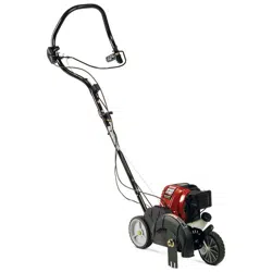
Fig. 14
STARTING/STOPPING INSTRUCTIONS
STARTING INSTRUCTIONS
(If cold, see Cold Weather Starting Insttructions
below)
STOPPING INSTRUCTIONS
1. Release your hand from the bail and move throttle
control lever to the SLOW ( ) position. Allow the
engine to cool down by idling.
2. Press and hold On/Off Stop Control in the OFF (O)
position until engine comes to a complete stop (Fig. 11).
1. Check the oil level in the crankcase. Refer to
Checking the Oil Level.
2. Fill the fuel tank with fresh, clean unleaded
gasoline. Refer to Fueling the Unit.
NOTE: There is no need to turn the unit on. The On/Off
Stop Control is in the ON ( I ) position at all
times (Fig. 11).
3. Fully press and release the primer bulb 10 times,
slowly. Some amount of fuel should be visible in
the primer bulb and fuel lines (Fig. 12). If you can’t
see fuel in the bulb, press and release the bulb as
many times as it takes before you can see fuel in it.
NOTE: If the temperature is below 40°F, move the
Cold Weather Start Lever to the closed position
(Fig. 13) and continue to step 4. DO NOT move
this lever to the closed position if the
temperature is above 40°F.
4. Stand in the starting position (Fig. 14) and make
sure the throttle control (Fig. 15) is in the SLOW
( ) position.
5. Pull the starter rope out a short distance until you
feel some resistance (this is usually around 2-4
inches). Then pull the starter rope smoothly and
briskly 5 times. The engine should start.
NOTE: Do not engage the bail while pulling the starter
rope (Fig. 14) or the unit will not start.
6. If the engine starts, move the throttle control to the
FAST ( ) position and allow the engine to warm
up for 15 to 30 seconds.
NOTE: If the engine starts and the temperature is
below 40°F, move the Cold Weather Start
Lever to the open position (Fig. 13) and let the
engine warm up for 30 to 60 seconds.
IF... the engine does NOT start, go back to step 3.
IF... the engine stops while the throttle control is in the
FAST ( ) position, go back to step 4.
Starter
Rope
WARNING:
Operate this unit only in a well- ventilated outdoor area. Carbon monoxide
exhaust fumes can be lethal in a confined area.
WARNING:
Avoid accidental starting. Make sure you are in the starting position when
pulling the starter rope (Fig. 14). To avoid serious injury, the operator and unit must be
in a stable position while starting.
Fig. 11
On/Off
Switch
OPERATING INSTRUCTIONS
HOLDING THE UNIT
Before operating the unit, stand in the operating position (Fig. 16).
Check for the following:
• The operator is wearing eye protection and proper clothing.
• Both hands are holding the handle bar firmly.
• The edger wheel adjusted for proper cut depth as shown in
Figure 17 and edger positioned as shown in Figure 16.
ADJUSTING EDGER CUTTING DEPTH
1. Grasp the depth adjustment lever located beside the front
wheel (Fig 17).
2. To raise the cutting blade, move the lever toward the front of
the wheel bracket (Fig. 17). Lowering the wheel decreases the
cutting depth.
3. To lower the cutting blade, move the lever toward the rear of
the wheel bracket. Raising the wheel increases the cutting
depth.
TIPS FOR BEST EDGING RESULTS
• Do not force the edger. Edge the first time at a lesser
depth,(No more than 1/2” depth cut per pass), then do the area
again with a deeper setting.
• Walk the edger at a slow, even pace.
• Check the blade condition. As it wears it becomes smaller,
thus reducing the cutting depth performance. Replace with a
new blade when the blade has worn to the blade’s wear limit
holes (Fig. 18).
ADJUST BELT TENSION
If blade fails to turn when the bail is pulled, then:
1. Locate small thumb wheel on top of the belt housing (Fig. 17).
2. Turn the wheel clockwise 1 revolution to increase the tension
on the belt.
3. Try pulling the bail and see if the blade turns. If not, repeat
step 2 until the blade turns.
WARNING:
Always wear eye, hearing, foot and body protection to reduce the risk of
injury when operating this unit.
Fig. 16
Fig. 17
Thumb
Wheel
Wheel Bracket
Depth
Adjustment
Lever
Fig. 18
Blade Edges
Wear Limit
Holes
MAINTENANCE AND REPAIR INSTRUCTIONS
MAINTENANCE SCHEDULE
Perform these required maintenance procedures at the frequency stated in the table. These procedures
should also be a part of any seasonal tune-up.
NOTE: Some maintenance procedures may require special tools or skills. If you are unsure about these
procedures take your unit to a Troy-Bilt or other qualified service dealer.
NOTE: Maintenance, replacement, or repair of the emission control devices and system may be
performed by a Troy-Bilt or other qualified service dealer.
In order to assure peak performance of your engine, inspection of the engine exhaust port may be
necessary after 50 hours of operation. If you notice lost RPM, poor performance or general lack of
acceleration, this service may be required. If you feel your engine is in need of this inspection, refer
service to a Troy-Bilt or other qualified service dealer for repair. DO NOT attempt to perform this process
yourself as engine damage may result from contaminants involved in the cleaning process for the port.
WARNING:
To prevent serious injury, never perform maintenance or repairs with unit
running. Always service and repair a cool unit. Disconnect the spark plug wire to ensure
that the unit cannot start.
FREQUENCY MAINTENANCE REQUIRED SEE
Before using
Fill fuel tank with fresh fuel
Check Oil
p. 4
p .6
Every 10 hrs Clean and re-oil air filter p. 6
After 1st 10 hrs
Every 25 hrs
Every 25 hrs
Change Oil
Change Oil
Clean Spark Arrestor
p. 6
p. 6
p. 7
Every 10 hrs
Verey 25 hrs
Every 25 hrs
Check rocker arm to valve clearance and adjust
Check rocker arm to valve clearance and adjust
Check spark plug condition and gap
p. 6
p. 6
p. 7
Fig. 15
Throttle
Control
Throttle Label
Fast
Slow
Bail
Fig. 12
Primer Bulb
Fig. 13
Cold Weather Start Lever
Open Closed
WARNING:
Do not force the throttle control
handle back past the Turtle on the throttle label.
This could damage the unit.
Loading ...
Loading ...
Loading ...