
TOLIFE kit User Manual
QUICK START GUIDE

Funded by the European Union. Views and opinions expressed are however those of the author(s)
only and do not necessarily reflect those of the European Union or the European Health and Digital
Executive Agency (HADEA). Neither the European Union nor the granting authority can be held
responsible for them.

1
In the present document, we describe the technical details
of the smart sensors that will be used in the TOLIFE clinical
studies, by reporting the producer manuals for commercial
devices (smartwatch, smartphone, and mini-spirometer) and
the hardware/software description for prototypal devices (smart
mattress cover, environmental unit and smart shoes).
WHY TOLIFE PROJECT?
TOLIFE main objective is developing and clinically validating
a platform based on articial intelligence and non-invasive
sensors to improve the management and personalization of
the treatment of highly complex chronic diseases.
The platform will be optimized and validated in “real life”
conditions on patients with chronic obstructive pulmonary
disease (COPD). TOLIFE’s approach to COPD management
consists in analysing data taken from the patient during daily
activities - thanks to a platform of wearable and non-invasive
sensors - in order to predict and mitigate exacerbations and
continuously evaluate the individual’s state of health patient to
reduce mortality, improve quality of life and mitigate healthcare
costs. Exacerbation prediction and health assessment will be
leveraged by clinicians through a patient management tool to
implement early and personalized treatment.
A software interface will also be developed for the patient to
inform him about his state of health, the specic treatment
plan and to provide useful information for a correct lifestyle.
2
Scan to download the digital manual

3
INDEX
1 DEVICE DESCRIPTION..................................................................................................................5
2 TOLIFE SENSOR KIT INSTALLATION AND USER MANUAL...............................6
2.1 Wi-Fi Router..........................................................................................................................6
2.2 Smartwatch....................................................................................................................................7
2.3 Smartphone................................................................................................................................................ 8
2.4 Smart Shoes........................................................................................................................10
2.5 Smart Mattress Cover and Environmental Unit...........................................12
2.6 Mini-Spirometer............................................................................................................16
3 MOBILE APP USER MANUAL............................................................................................17
3.1 MINI-SPIROMETER step-by-step guide..........................................................18

4
5
The TOLIFE sensor kit will be used during the clinical study A (observational prospective cohort study)
to collect raw data associated to symptoms, performance, electrophysiologic signals and environmental
variables relevant for the estimation of the health status of COPD patients.
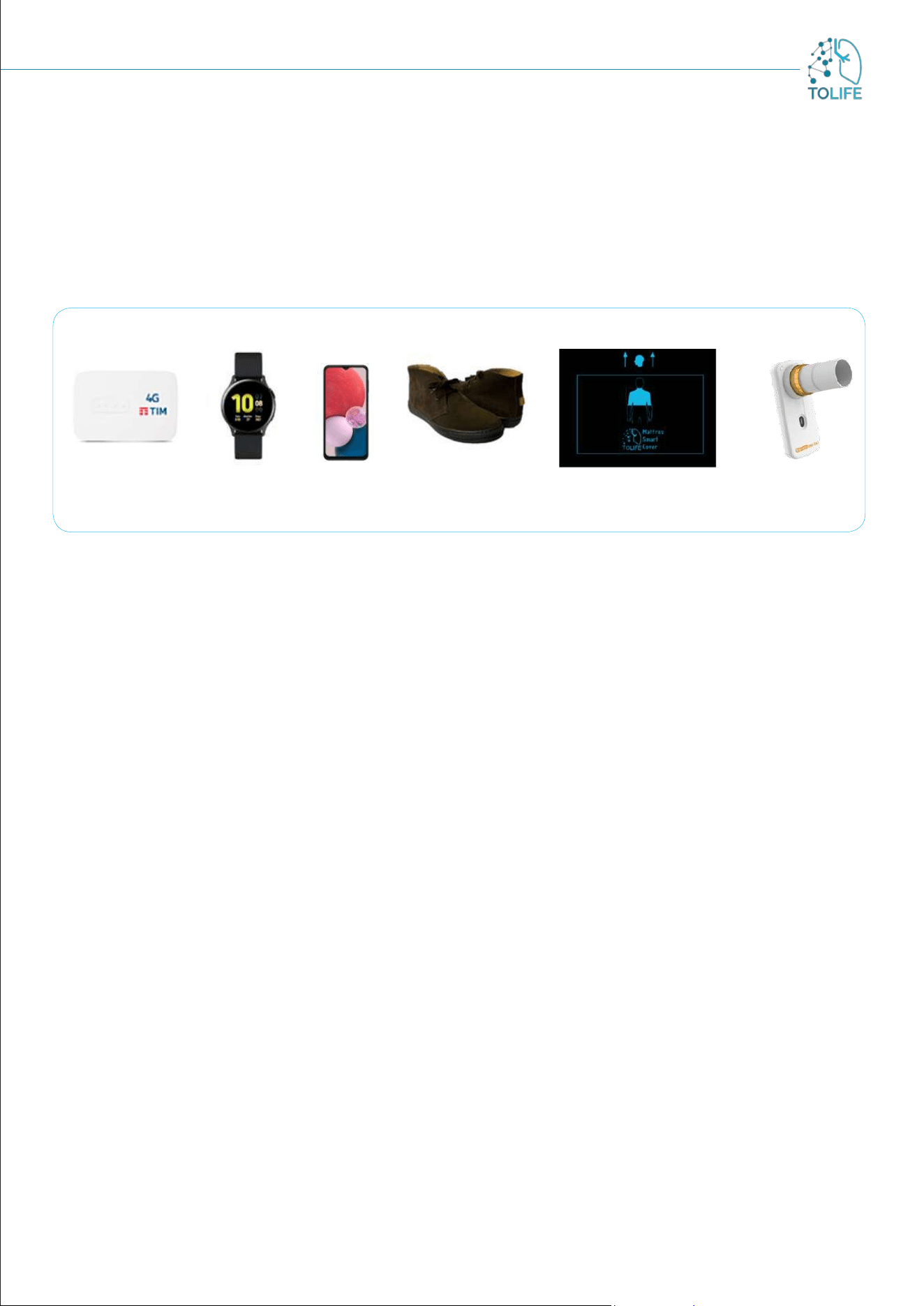
The TOLIFE sensor kit (Figure 1) consist of:
• Wifi Router
• Smartwatch
• Smartphone
• Smart Shoes
• Smart mattress cover with Bedroom Box Case (a device that detects environmental parameters
such as light, temperature, humidity and noise, useful in monitoring the surroundings)
• Mini-Spirometer
In addition, the following accessories are included in the kit you received:
Chargers and cables:
• 1 transformer triple sockets + 3 cables (Smartphone, Smartwatch, WiFi Router)
• 1 transformer + 1 cable for Smart shoes
• 1 power supply for the Bedroom Box Case
• 1 USB cable to connect Smart mattress cover and Bedroom Box Case
Manual (both paper and digital)
Data from the smart sensors will be uploaded to the TOLIFE database through the Wifi connection provided
by the Wifi Router.
Figure 1: TOLIFE sensor kit
1 DEVICE DESCRIPTION
WiFi Router
Smart mattress cover
Smartwatch
Smartphone
Smart Shoes Mini Spirometer
6
2 TOLIFE SENSOR KIT INSTALLATION
AND USER MANUAL
Each of the elements of the kit (Figure 1) has separate power-up instructions that should be followed when
the kit is installed for the first time. The different devices can be switched on in no specific order, except
for the Wifi Router, which must necessarily be switched on first.
It is opportune to place the Wifi Router in the same room as the Smart Mattress Cover (bedroom) to aid
communication, or alternatively in an adjacent room. During the recharging phase, which will be explained
in detail in the following sections, the Smartphone and Smartwatch should be placed in the same room as
the Wifi Router, or alternatively in an adjacent room..
FIRST INSTALLATION
To install the device for the first time, take the power supply with
cable out of the box and plug it into a power outlet in the room (Figure
3A).
It is important to place the unit in the same room where the Bedroom
Box Case is located or if not possible, in a nearby room.
Connect the USB cable to the Wifi Router (Figure 3B).
Press and hold the side button (Figure 3C) until all LEDs light up
(Figure 3D).
The router will power on and automatically set up a Wifi network for
devices to connect to.
Figure 3: A) B) plugging instructions, C) Side Button, D) LEDs light up
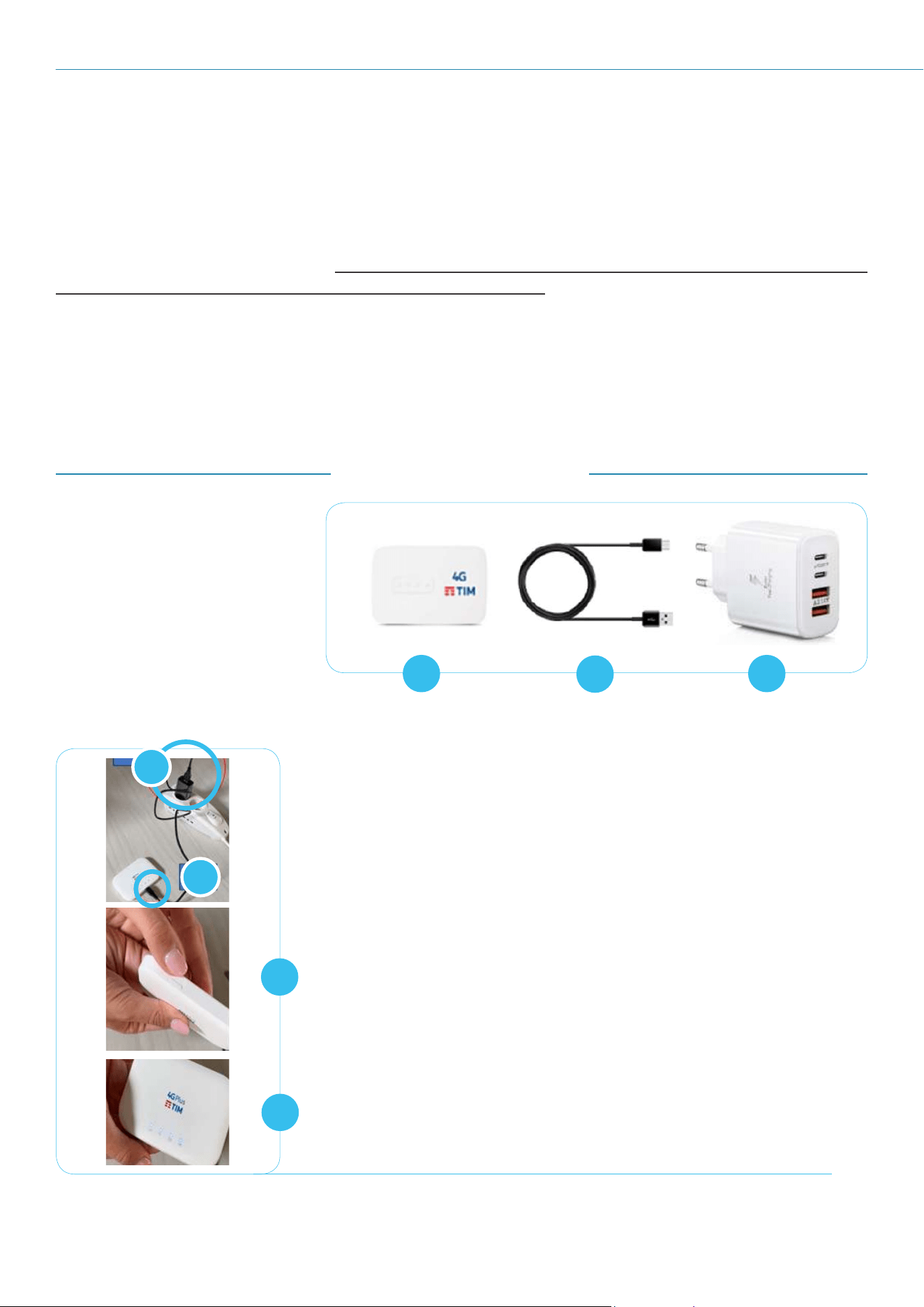
Figure 2: A) Wifi Router, B) USB cable, C) power supply
B
C
D
A
A
B
C
The elements of the Wifi Router
device are:
• Wifi Router with
integrated sim (Figure 2A)
• USB cable (Figure 2B)
with power supply
(Figure 2C)
2.1 WI-FI ROUTER
7
USE AND CHARGING
The device requires no special maintenance and care. Please never disconnect the router from the power
supply. Keep in mind that it should always be located in the same room (or in an adjacent one) where other
devices are charged and connected.
RESTART INSTRUCTIONS
In case of device malfunction, please restart it by following the steps below:
Press and hold the side button (Figure 3C) until all LEDs light off
Wait 30 seconds
Press and hold the side button (Figure 3C) until all LEDs light up
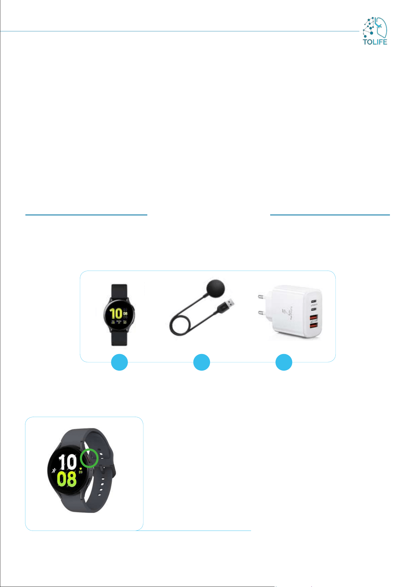
2.2 SMARTWATCH
The elements of the Smartwatch device are:
• Smartwatch (Figure 4A)
• USB cable with magnetic charger (Figure 4B) and power supply (Figure 4C)
Figure 5: Smartwatch buttons
FIRST INSTALLATION
For the first installation, take the power supply with cable and connect
it to a power socket. It is advisable to choose a socket in the same
room where all other devices will be charged and connected. Switch
on the smartwatch using the side button with a red inner border
(Figure 5: smartwatch buttons, green circle). The device will take
some time to start up (2-3 minutes). When the clock appears on the
screen, the smartwatch is ready to be used. The TOLIFE application
will start automatically and the information about the application
status is displayed on the screen.
A B C
Figure 4: A) smartwatch, B) USB cable with magnetic charger, C) power supply
8
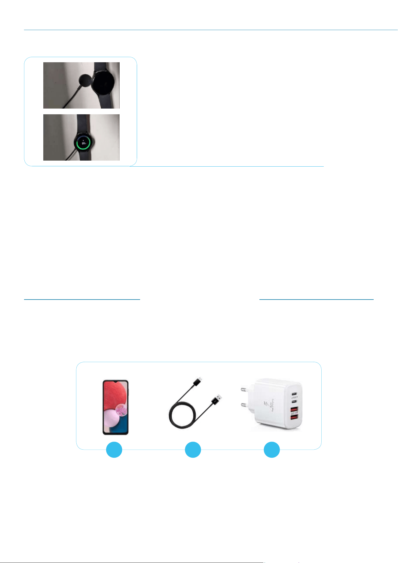
Figure 6: Place the smartwatch on the magnetic charge
USE AND CHARGING
Recharging the smartwatch is crucial, as the battery typically lasts
around 8 to 10 hours.
Therefore, regularly monitor the battery level and recharge it when
the device's power is running low. Use the magnetic holder connected
to the power socket (as shown in Figure 6) for charging.
RESTART INSTRUCTIONS
In case of device malfunction, please restart it by following the steps below:
Press and hold the side button with a red inner border (Figure 5) smartwatch buttons, green
circle) until you see the power off screen
Once the power off screen appears, swipe left or right until you find the option to restart
Tap on the restart option
Your smartwatch will now power down and then restart
A B C
Figure 7: A) smartphone, B) USB cable, C) power supply
2.3 SMARTPHONE
The elements of the Smartphone device:
• Smartphone (Figure 7A)
• USB cable (Figure 7B) with power supply (Figure 7C)
9
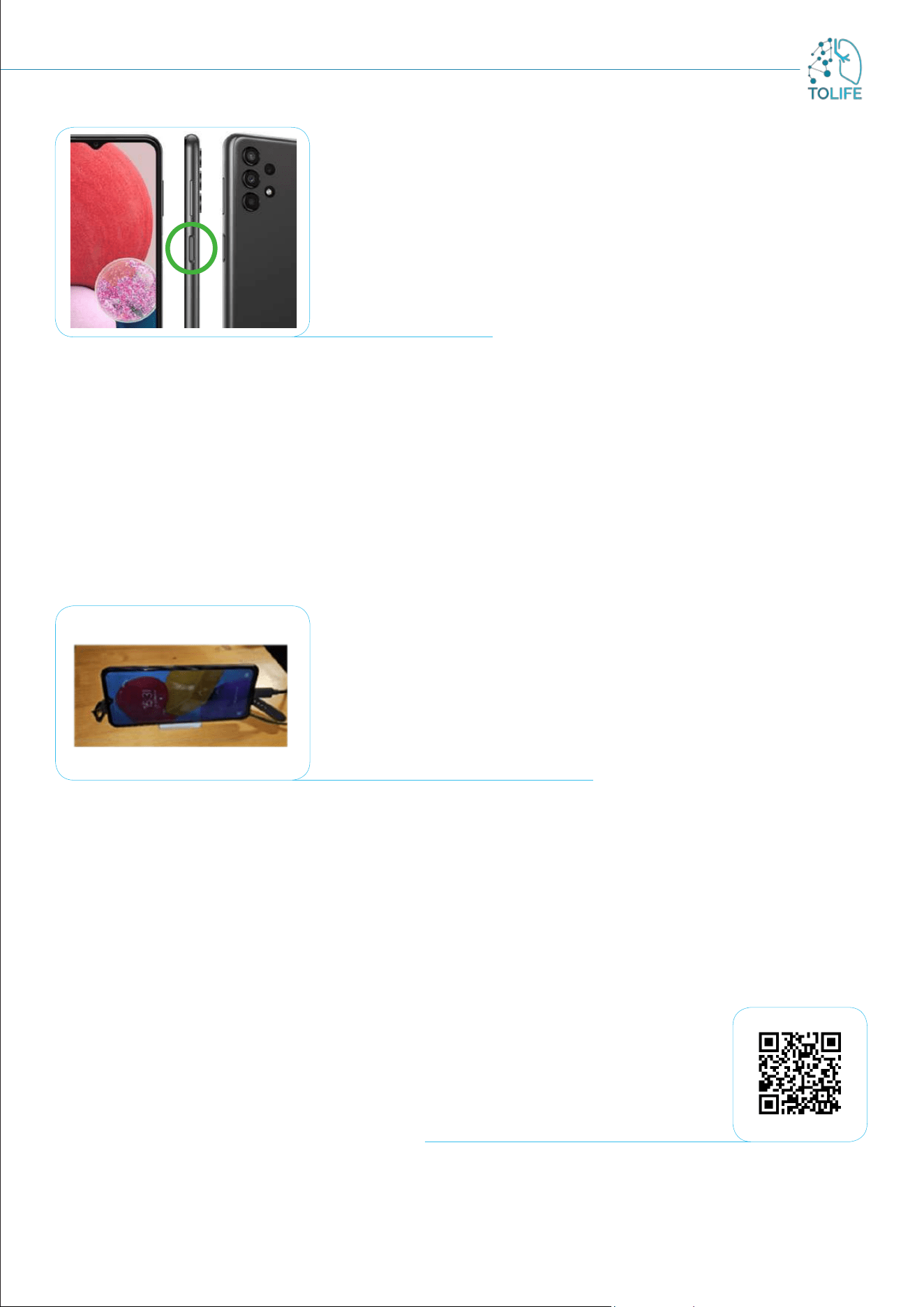
FIRST INSTALLATION
During the first installation, switch the smartphone on using the side
button (Figure 8: side button, green circle).
The device is now ready for use.
Figure 8: side button
USE AND CHARGING
The device does not require special maintenance and care; please note that the Bluetooth connection has
to remain always active to ensure proper functioning of all tools in the kit.
During usage, especially when the phone is in your pocket or bag, it is advisable to put it on standby using
the side button. This helps prevent unintentionally opening of other apps.
When the device’s battery is running low, please recharge it using the provided power cable in the kit
(Figure 9).
Figure 9: smartphone under charge
RESTART INSTRUCTIONS
In case of device malfunction, please restart it by following the steps below:
Press and hold the side button (Figure 8: side button, green circle) until you see the power off
screen
Once the power off screen appears select the “Restart” option
Your smartphone will now power down and then restart
You can use any power outlet, preferably in the same room where all
the other devices are plugged and charged.
Scan to play the video
10
A B C
Figure 10: A) Smartshoes, B) USB cable, C) Power supply
FIRST INSTALLATION
Smart shoes do not require any first installation.
2.4 SMART SHOES
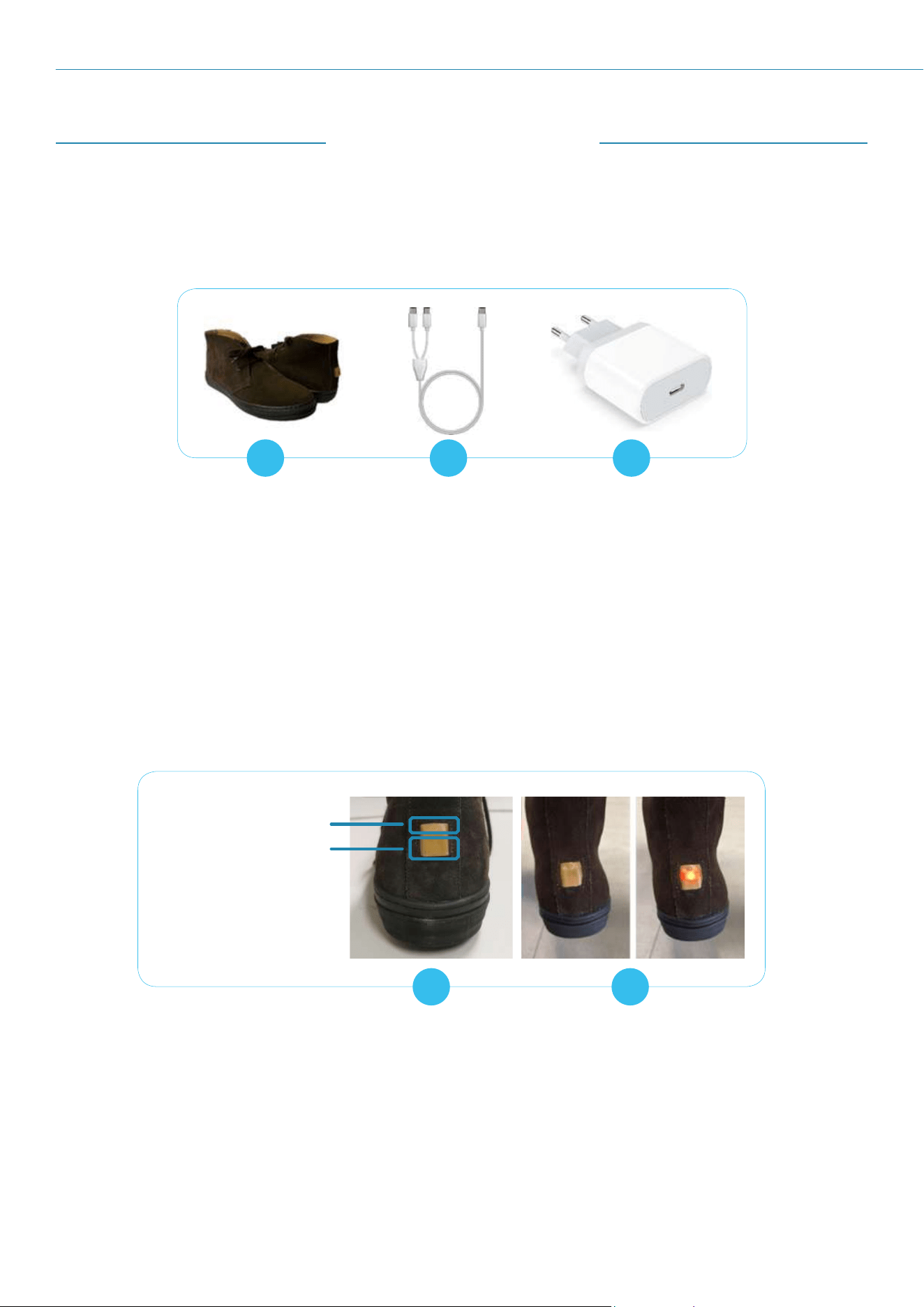
The smart shoes device elements:
• Smart shoes (Figure 10A)
• USB cables x2 (Figure 10B) for charging with the power supply (Figure 10C)
USE AND CHARGING
Activate the smart shoes by pressing the power button positioned on the back (Figure 11A). Upon activation,
you will see a LED lighting up. When the button is released the LED will start flashing (Figure 11B).
A B
Figure 11: A) power button and charge socket, B) power LED light
Power button
Charge socket
The shoes are now ready for use and you can wear them. Please note that the shoes only work if they are
in close contact with the smartphone. When wearing them, pay attention to always have the smartphone
close to you (for example in the pocket, in your pursuit, etc.).
In the first minute after activation the LED will flash at very short intervals (1 sec.), then after about a
minute the LED will turn off.
11
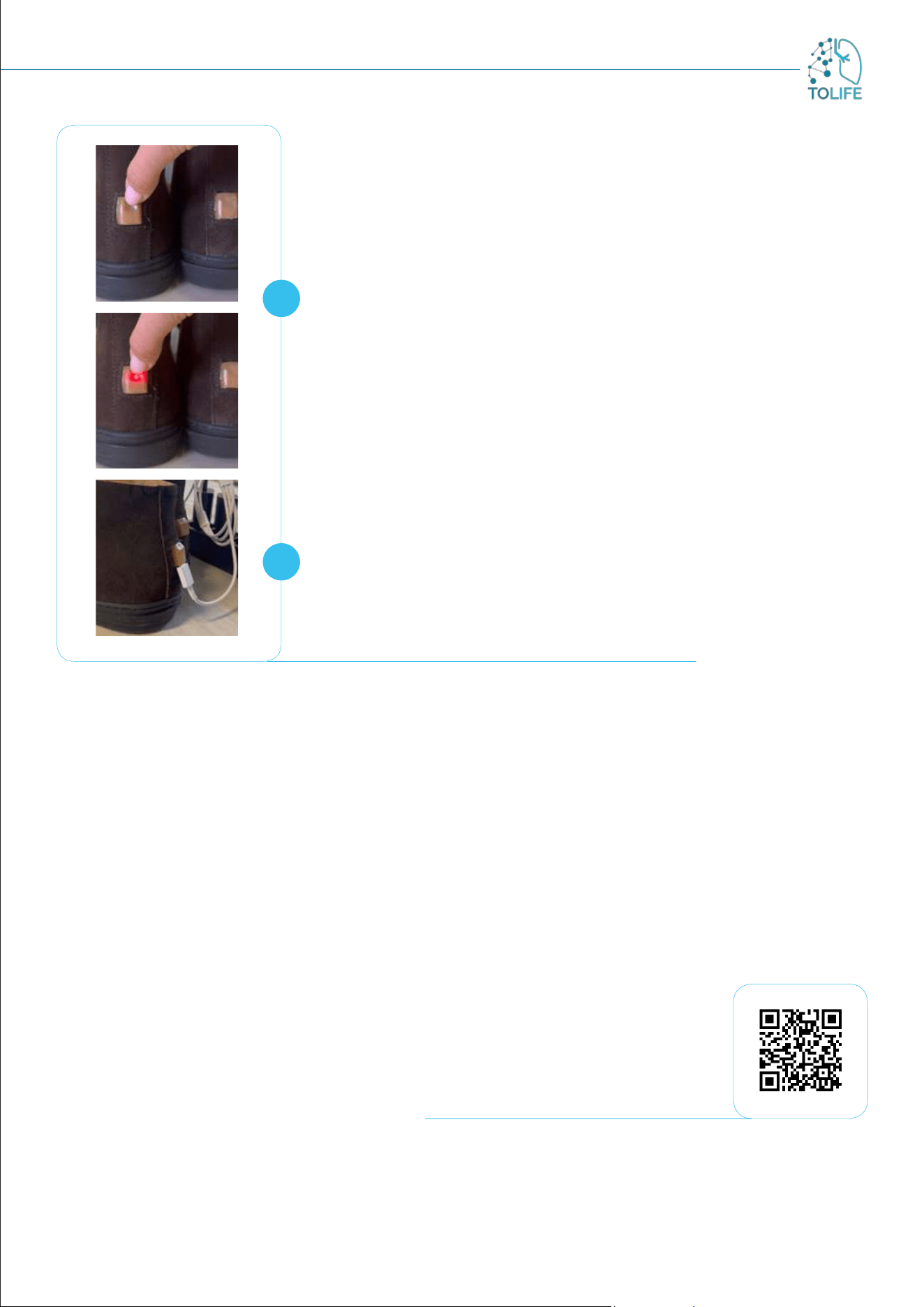
The device does not require any special precautions during use.
If you want to check if the shoes are active, press the button and hold
it down for a very short time (about 1 sec.) triggering the LED lighting
up. When you release the button the LED could be in one of these
two stages:
1) the LED turn off meaning the shoe is correctly turned on (Figure
12A).
2) If the LED starts flashing meaning the shoe was previously turned
off and now you have turned it on (Figure 12A).
If you press the button and the LED does not light up, it means that
the shoes have a low battery level.
In case you want to turn off the shoes, press and hold the power
button until the LED turns off (about 3 seconds). (Figure 12A).
It is recommended to switch off and charge the shoes overnight.
Charging need not take place in the same room as the Wifi Router.
To recharge, plug the USB cable into the USB socket on the back
of the shoes and connect the other end to the power supply (Figure
12B). The shoes can be used and worn without time restrictions.
Figure 12: A) Power check, B) Shoes under charge
A
B
RESTART INSTRUCTIONS
In case of device malfunction, please restart it by following the steps below:
Turn off the smart shoes by pressing the power button on the back of the shoes (Figure 11A). ).
When they switch off, the LED light will light off
Wait 30 seconds
Turn on the smart shoes by pressing the power button on the back of the shoes (Figure 11A).
When they switch on, you will see the LED light up. When the button is released, the LED will
start flashing (Figure 11B)
If pressing the power button, the LED does not light up, it means that the shoes have a low
battery level and need to be recharged.
Scan to play the video
12
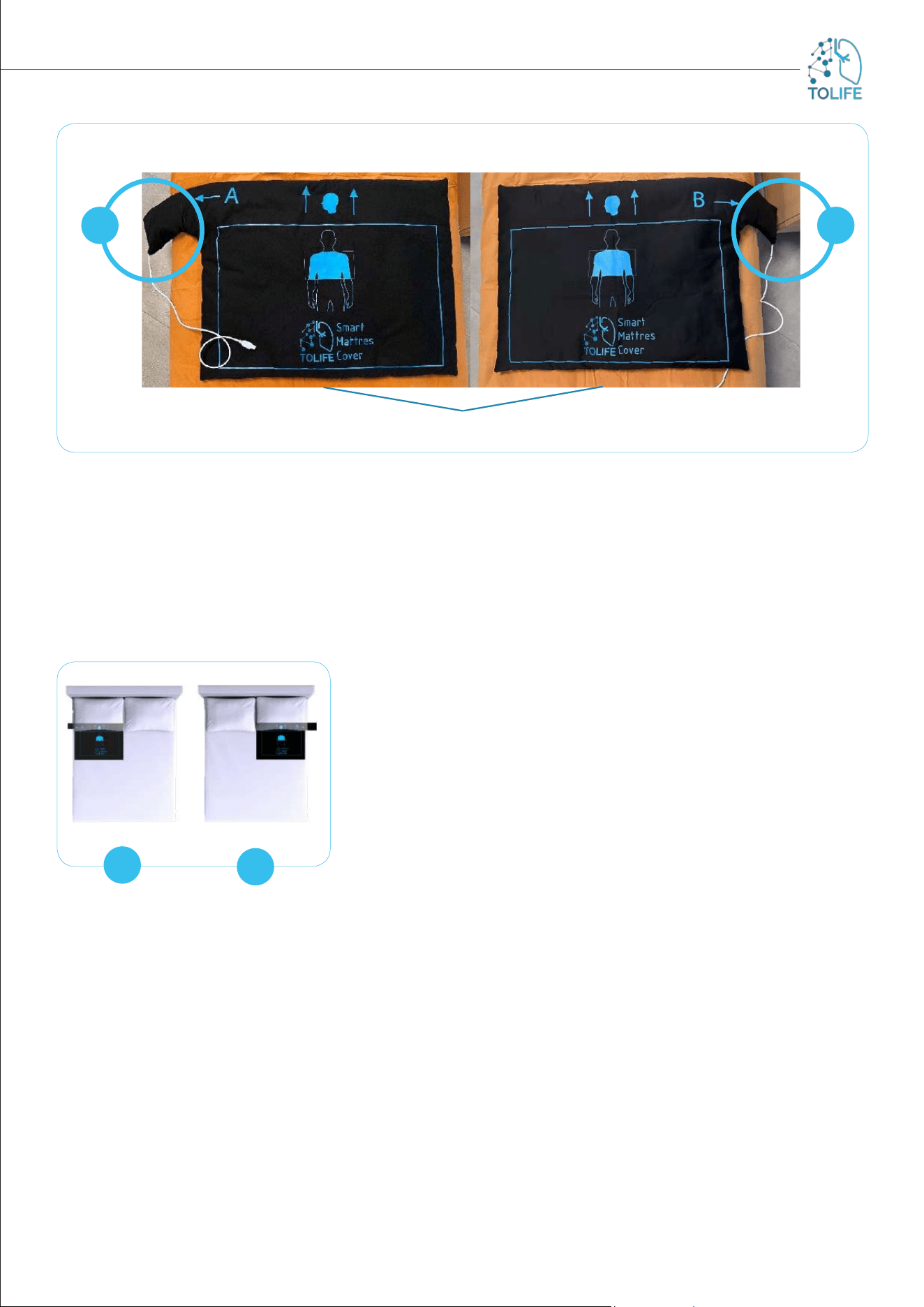
FIRST INSTALLATION
The Smart Mattress Cover comes with a sensing cover and a side pocket where the BedSide electronic
integrated board is inserted. The cover has two different sides that define two possible conFiguretions of
the system; each side conFiguretion is indicated by A/B labels printed on the cover, followed by an arrow
that points the electronic board pocket.
The Figure 14 shows clearly:
• ConFiguretion A has the sensing cover with the electronic board pocket placed on the left side.
• ConFiguretion B has the electronic board pocket positioned on the right side.
2.5 SMART MATTRESS COVER
AND ENVIRONMENTAL UNIT
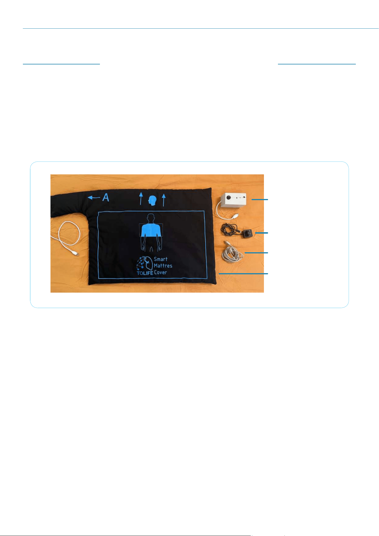
The Smart Mattress Cover device includes the following (Figure 13):
• Smart Mattress Cover with integrated BedSide electronic unit
• Bedroom Box Case
• USB extension cable
• Power supply unit
Take note that the cover has printed information on both sides to help you in performing the installation.
Figure 13: All the elements supplied with the Smart Mattress Cover
BEDROOM Box Case
Power Supply
USB Cable
Smart Mattress Cover
13
Figure 14: Smart Mattress Cover hardware conFiguretion A) Side A and B) Side B
Please, select one of the two sides according to the characteristics of your bed and bedroom. If you choose
conFiguretion A, you have to place the cover on the bed with the letter A facing upwards (Figure 14A). If,
alternatively, you choose conFiguretion B, you just have to place the cover on the bed with the letter B
facing upwards (Figure 14B).
For the first installation of the Smart Mattress Cover, please follow the assembling instructions provided
below.
SIDE OF THE BED:
In a double-bed, the Smart Mattress Cover has to be placed on the
side where you sleep. As shown in Figure 15A e B, the electronic
board pocket should be positioned outside the bed and close to the
nightstand.
In a single-bed, it is recommended to choose the cover conFiguretion
that avoids to place the electronic board pocket on the sides with
external encumbrances, such as a wall. If the single bed hasn’t external
encumbrances and the placement is indifferent, kindly be aware that
selecting ConFiguretion A is recommended.
Lateral pocket with
Bed Side unit
Lateral pocket with
Bed Side unit
SMART MATTRESS COVER
A B
Figure 15: A) side A conFiguretion
B) side B conFiguretion
A
B
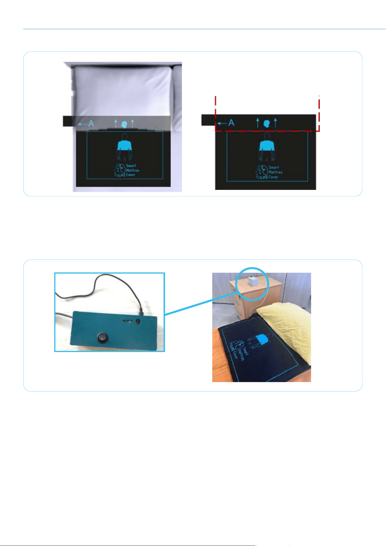
POSITION OF THE COVER
After choosing the side, the printed head and thorax indications on the cover assist in correctly positioning
the Smart Mattress Cover. Now, please place the Smart Mattress Cover with the edge of the blue rectangle
aligning with the bottom edge of the pillow, as in Figure 16.
The upper part indicates where the head should be inserted under the pillow, while the rectangle should be
placed at the chest level. Once the system is correctly placed on the mattress, you can finish making the
bed with sheets according to your preferences. This may include adding another mattress cover on top or
covering it directly with sheets.
14
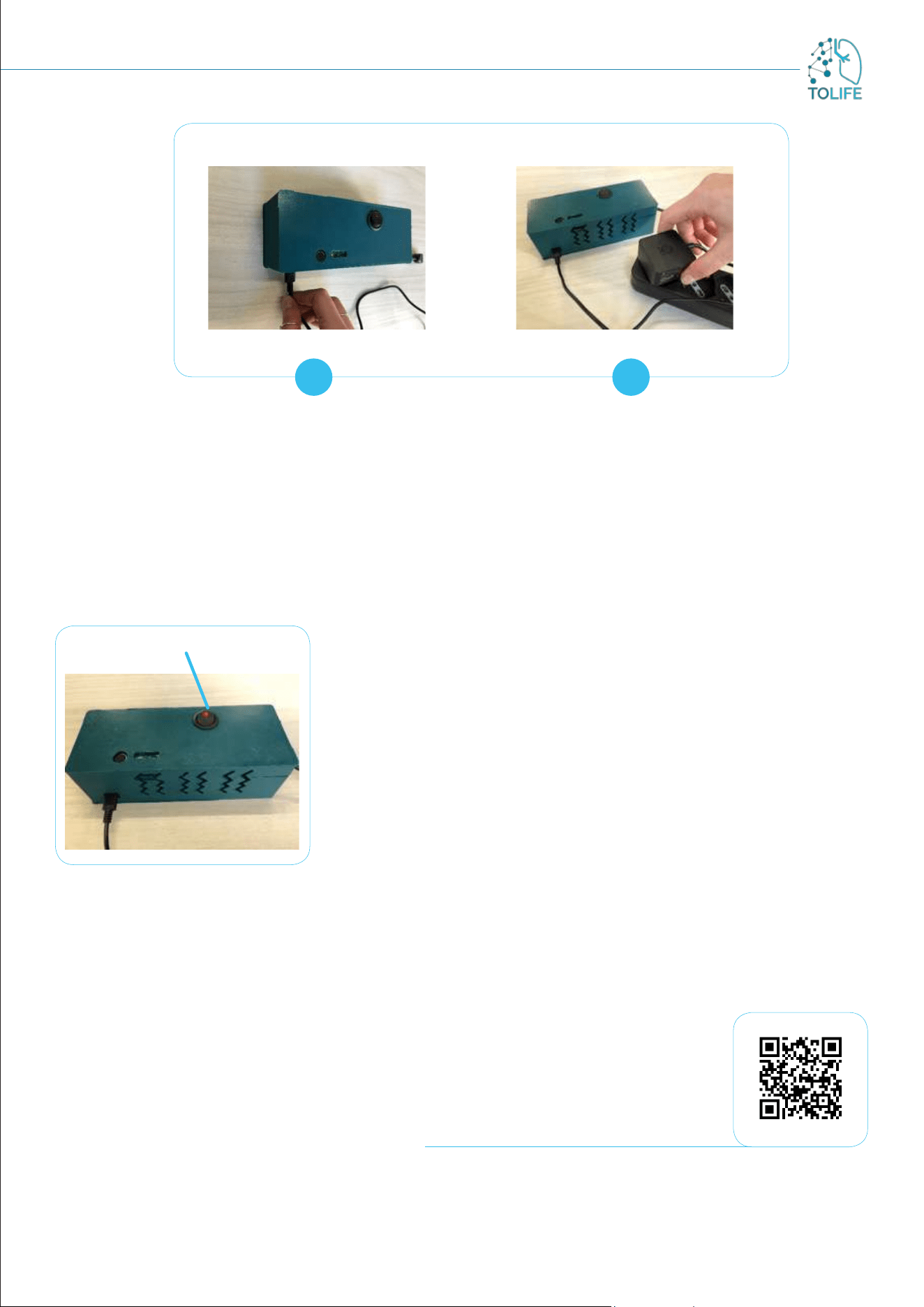
Now, please connect the Bedroom Box Case to the house power supply. This is done by inserting the USB-C
connector of the power supply unit into the port located on the side of the device (Figure 18A), and then
plugging it into a socket close to the chosen location for placing the system (Figure 18B).
The system is now ready for use.
Under the pillow
Figure 16: Correct placement of the Smart Mattress Cover
Figure 17: Bedroom Box Case placement
After the correct installation of the Smart Mattress Cover, the Bedroom Box Case should be positioned on
the bedside table or other nearby furniture, according to your preferences (Figure 17).
15
Figure 18: A)power supply hole location; B) connection of the Bedroom Box Case plug
in the closest socket.
A B
USE
The Smart Mattress Cover can be easily activated by pressing the “ON” button on the Bedroom Box Case
(Figure 19). The power LED integrated in the button will light up to indicate that the entire device is
activated and ready to use.
The device can be switched off by pressing the same button, the
power LED will turn OFF to indicate that the system is turned off.
As indicated, please pay attention to the correct use of sockets and
to the correct position of the Smart Mattress Cover. Check that the
power LED on the Bedroom Box Case is “ON” when using the system.
RESTART INSTRUCTIONS
In case of device malfunction, please restart it by following the steps
below:
Press the “ON” button on the Bedroom Box Case, the power
LED will turn OFF
Remove the plug from the socket
Wait 30 seconds
Insert the plug into the socket
Press the “ON” button on the Bedroom Box Case, the power
LED will turn “ON”
Power LED ON
Figure 19: Power LED ON indicates
the correct activation
of the Bedroom Box Case
Scan to play the video
16
The elements of the Mini-Spirometer device:
• Mini-Spirometer (Figure 20) (including oximeter sensor)
• Batteries
Figure 20: Spirometer
FIRST INSTALLATION
The device is ready for use. The batteries are already inserted. The Mini-Spirometer device comes with an
application already installed in the smartphone provided in the TOLIFE kit
USE AND CHARGING
The spirometer (with included oximeter) is the only device on TOLIFE
sensor kit that requires active actions. To perform a measurement
session with the spirometer, you should follow the guided procedure
provided by the “TOLIFE HUB” mobile application installed on the
smartphone.
Therefore you should start the “TOLIFE HUB” app and then following
the procedure for adding a record of spirometer and oximeter
measurements.
Figure 21 shows the icon of “TOLIFE HUB” mobile application on
smartphone screen. For a step-by-step description of spirometer and
oximeter data collection procedure, see the following section 3 (Mobile
App user manual).
Figure 21: IIcon of “Tolife hub”
application on smartphone
2.6 MINI-SPIROMETER
17
3 MOBILE APP USER MANUAL
The “TOLIFE HUB” mobile application is installed on the smartphone.
Therefore, you don't have to install any app. The app starts
automatically in background to collect data from the smartphone and
smartshoes and to send them to the TOLIFE database. The only action
required is to start the procedure for mini-s pirometer and oximeter
data collection.
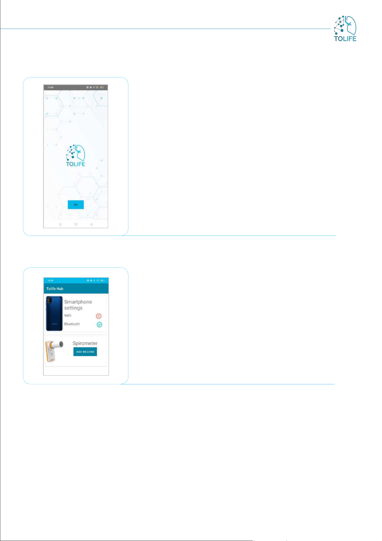
Firstly, you have to start the visual interface of “TOLIFE HUB”
app by clicking on the icon on smartphone screen (see Figure 21).
Subsequently, the initial visual page of the app will appear featuring
the TOLIFE project logo. You will need to click on the “GO” button
(Figure 22).
Figure 22: Opening screen page of “TOLIFE HUB” app
Figure 23: “TOLIFE HUB” app page with list of connected devices
Then, a new page appears: all the devices currently connected and
the connection mode (wifi or bluetooh) will be shown (Figure 23).
In the Mini-Spirometer section there is an “ADD RECORD” button
(Figure 23).
If you want to carry out a data collection session with the spirometer,
you have to click on the “ADD RECORD” button, so that the step-by-
step guided instructions start.
18
3.1 MINI-SPIROMETER STEP-BY-STEP GUIDE
The Mini-Spirometer device comes with an application already installed in the smartphone provided in the
TOLIFE kit. The application is ready to be used, without any conFiguretion step required. The application
is designed to guide you through a step-by-step procedure which includes (1) spirometry test, (2) a report
of the spirometry test performances, and (3) oximetry test, which provides the values for the average blood
oxygen saturation (SpO
2
) and heart rate (HR).
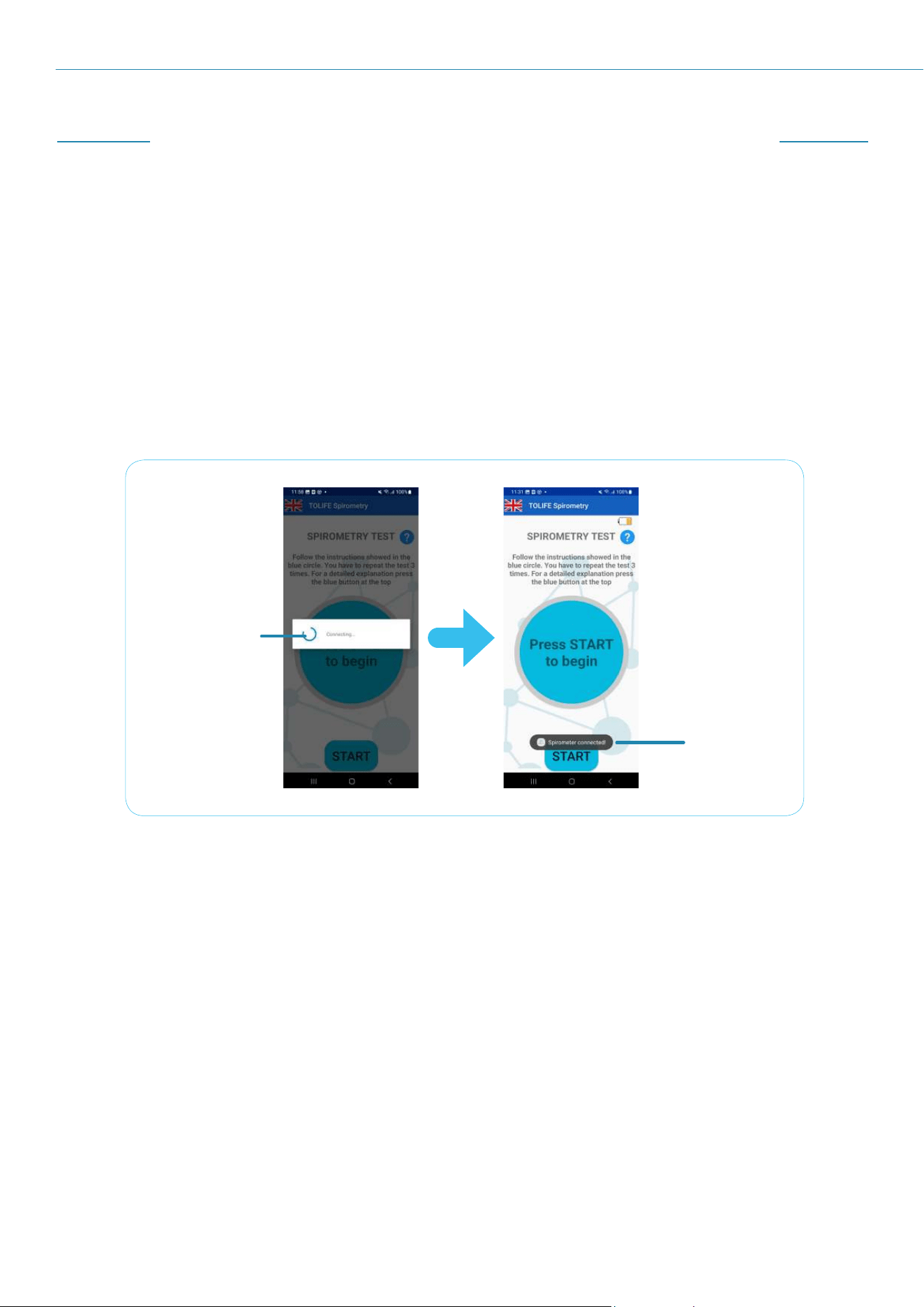
BLUETOOTH CONNECTION
After pressing “ADD RECORD” in TOLIFE Hub application (see previous section), the screen in figure
24 appears; a Bluetooth connection between the smartphone and the Mini-Spirometer is performed
automatically, as shown in Figure 24 below.
Connection
in progress
Connection
completed
Figure 24: Mini-Spirometer application start and Bluetooth connection
with the Mini-Spirometer device
First, the smartphone searches for the specific Mini-Spirometer device provided in the kit. Second, the
message “Spirometer connected!” appears at the bottom of the screen when the Bluetooth connection
procedure is complete.
This procedure is fully automatic, and it does not require any action.
19
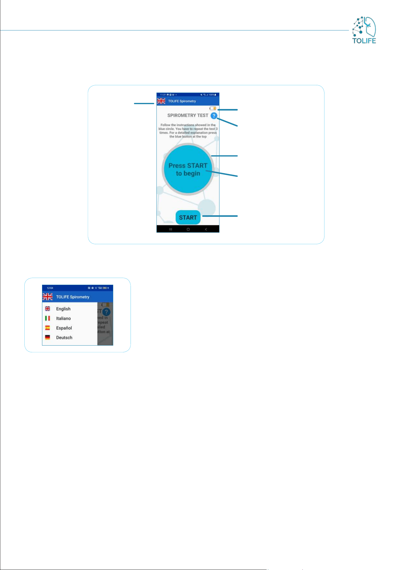
Once the Mini-Spirometer and the smartphone are connected, the application will show the Spirometry
Test page shown in Figure 25.
Spirometer battery
level
Information button
Progress bar
Measurement
instructions
Start measurement
button
Language
selection
Figure 25: Spirometry test main screen
The application automatically sets the language according with the
default settings of the smartphone. Therefore, if the default smartphone
language is English, the application will appear to the user in English.
The current application language is indicated by the corresponding
country flag (Figure 25, “language selection”). To change the language,
press on the country flag symbol. A menu will appear from the left
(Figure 26), showing a list of the available languages.
The application supports English, Italian, Spanish and German. Press
on the desired language to set it as default
Figure 26: Language selection menu
At the top right of the screen, an icon indicates the Mini-Spirometer battery level. If the charge level is too
low, an alert message will ask you to replace the old batteries with new ones. Until then, the application
will not allow you to take any measurement.
20
SPIROMETRY TEST
The spirometry test is made of three repeated trials. Please follow the instructions displayed in the
“measurement instructions” light blue circle at the center of the screen.
Each trial consists of two phases:
The blue circle turns yellow, and the “Blow” instruction appears. Please take a deep breath and blow
at your maximum capabilities for about 1 second;
The circle turns green, and the “Stop” instruction appears. Please stop blowing and recover (for
a detailed explanation of how to carry out a spirometry measurement, please see the Spirometry
measurement guidelines at the end of this manual).
A circular blue progress bar will appear, progressively surrounding the measurement instruction circle as
the trial completes.If you need more detailed information about how to perform a correct measurement, the
“Information button” will display a dialog window with a detailed set of instructions to follow, including what
should and what should not be done to carry out the spirometry test successfully.
To start a new spirometry test, press the “START” button at the bottom of the screen.
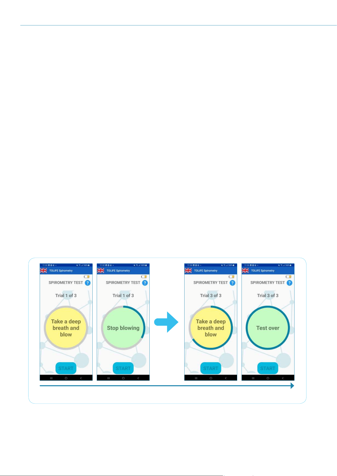
Figure 27 shows an example of a spirometry test. The current trial number to perform is displayed at the top
(e.g., “Trial 1 of 3”). The “Information button” is still available to provide detailed information about the test
at any moment. At the start of each trial, the measurement instruction circle changes its color to yellow,
showing the “Blow” instruction. Please take a deep breath and blow at your maximum capabilities into
the Mini-Spirometer, until the circle turns green and the “Stop” indication appears. Importantly, you can
take your own time to recover between one trial and another. At the end of the third trial, the “Test over”
instruction informs that the test is completed.
Start of spirometry test End of spirometry test
Figure 27: Example of spirometry test. The test consists of three repeated trials. A blue progress bar will
progressively surround the measurement instruction circle to inform the user about the number of trials
already completed. Simple instructions will be given in the yellow/green circle (yellow: take a deep breath
and blow; green: stop blowing and rest).
21
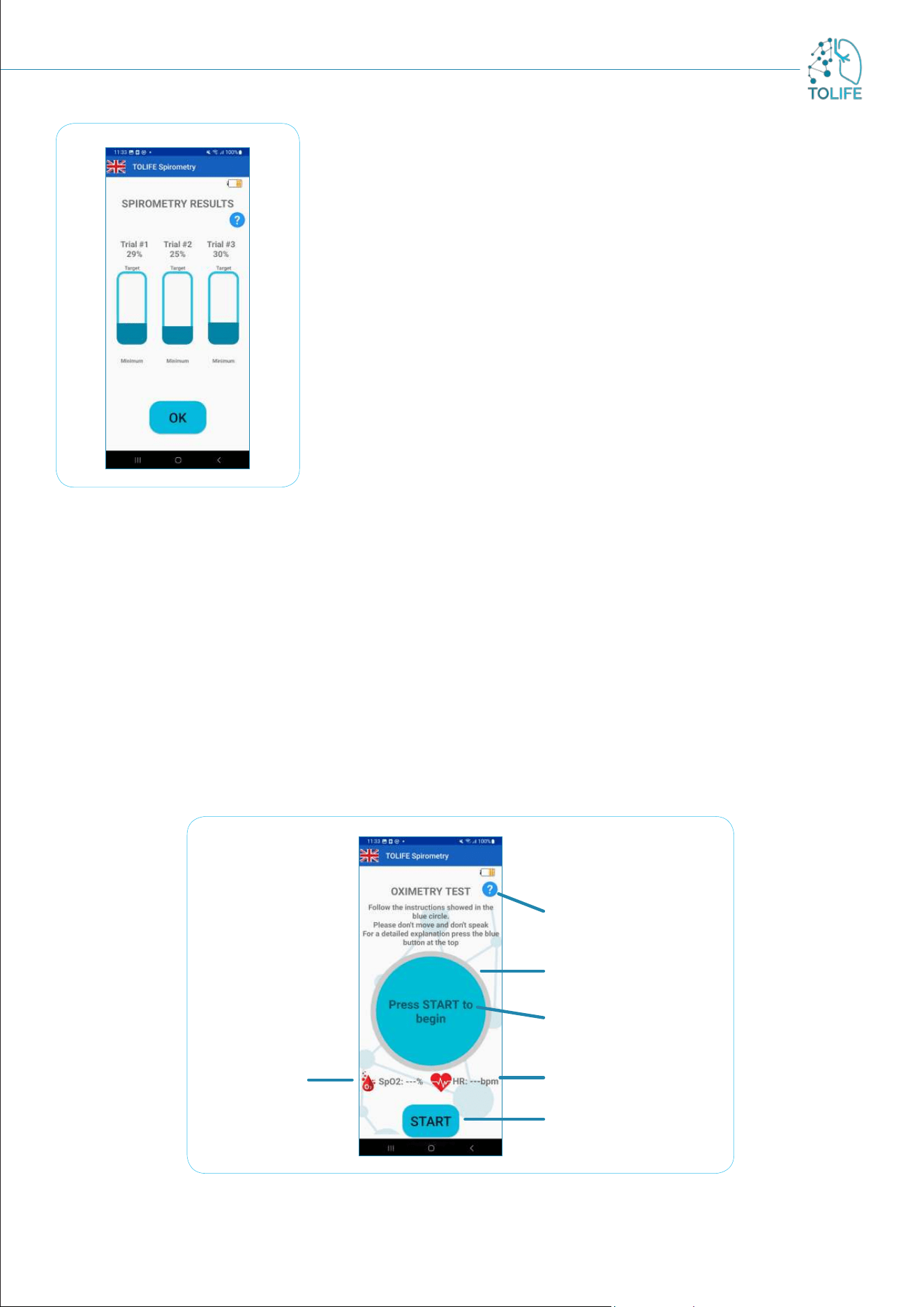
SPIROMETRY TEST RESULTS
Once the spirometry test is over, a summary of the results is displayed
(“Spirometry Results”; Figure 28).
Specifically, for each of the three trials is reported the percentage
of Forced Expiratory Volume in 1 second (FEV1) with respect to a
predefined target value. This value is automatically computed based on
your personal information, including age, gender, height and weight.
Notably, these parameters are already stored inside the smartphone
and cannot be accessed or edited by anybody to preserve your privacy.
The blue information button at the top right of the screen provides a
detailed explanation of the way spirometry results are presented and
reported.
Press the “OK” button at the bottom of the screen to close the
spirometry results and switch to the oximetry test (Figure 29).
Figure 28: summary of the
spirometry test results. For each
of the three trials, the result is
reported in terms of the percentage
with respect to the target value.
OXIMETRY TEST
Like the spirometry test, the oximetry test presents an information button at the top right of the screen that
provides you with exhaustive information about the measurement procedure (see Figure 29). Furthermore,
a blue circle at the center of the screen provides simple and intuitive instructions.
This circle is surrounded by a grey progress bar that progressively changes its color to blue as the measurement
proceeds towards the end. Below the measurement instructions circle, two indicators will show you the
average blood oxygen saturation (SpO
2
; left) and heart rate (HR; right), respectively.
Figure 29: Oximetry Test main screen
Heart Rate indicator
Blood
oxygen
saturation
indicator
Start measurement
button
Progress bar
Measurement
instructions
Information button
22
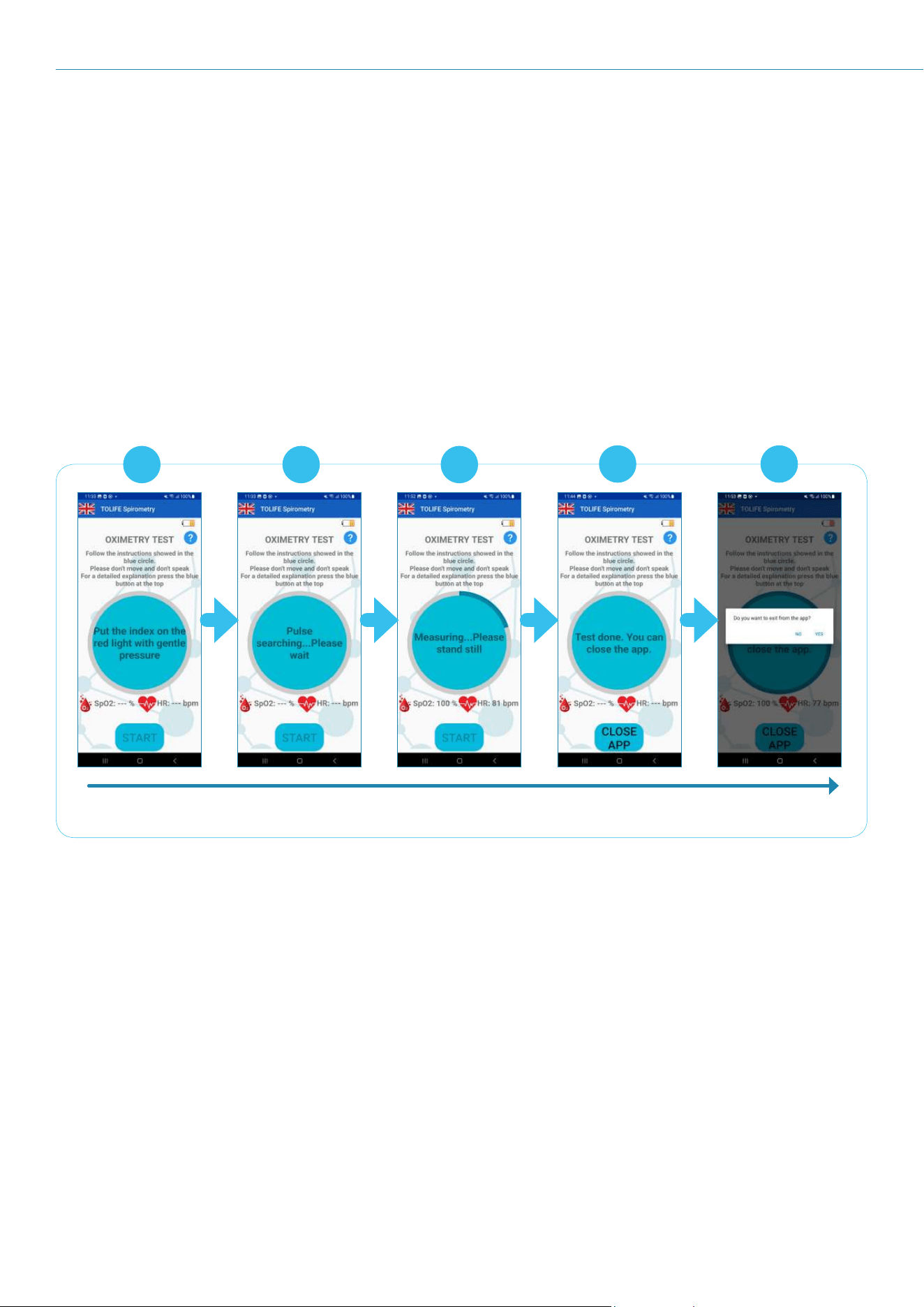
To start a new oximetry test, press the “START” button at the bottom of the screen and follow the steps
shown in Figure 30:
Place your index above the red light of the Mini-Spirometer sensor (Figure 30A). Your finger must
cover the light completely, without applying too much pressure.
The Mini-Spirometer starts searching for the pulse signal (Figure 30B). This procedure may take
several seconds.
The measurement starts (Figure 30C) and has a duration of 10 seconds. It is mandatory to avoid
movements and speaking. The SpO
2
and HR indicators will be updated with their average estimates
while the measurement is in progress.
The overall test is over, and the application can be closed (Figure 30D). To close the application,
please press the “CLOSE APP” button at the bottom of the screen.
An alert message will appear asking whether you are sure to close the application. Please press
“yes” to close the application (Figure 30E).
Start of oxymetry test End of oxymetry test
B C
D E
A
Figure 30: Example of oximetry test.
PLEASE NOTE: the pulse searching procedure (step B; Figure 30) may fail due to several reasons, which
include cold hands, speaking, and movements. To guarantee the collection of reliable measurements, the
application performs several internal checks including the quality of the pulse signal itself and starting a
countdown timer. If the Mini-Spirometer fails to detect the pulse signal because of either low signal quality
or the expired time, the measurement is canceled and a window appears, providing a list of actions that
should be followed to improve the measurement (Figure 31A). By pressing on the “Retry” button and then
on “Start”, the oximetry test can be repeated for two more times, for a total of three attempts. If the
pulse searching procedure keeps failing, a second window informs that a reliable measurement can not be
performed at the moment and to try later (Figure 31B). Please press on the “OK” button, the screen will
instruct to close the application (Figure 31C). To close it, press the “CLOSE APP” button at the bottom of
the screen. A message will appear, asking one more time if you are sure to close the application. Press “yes”
to close the application (Figure 30E).
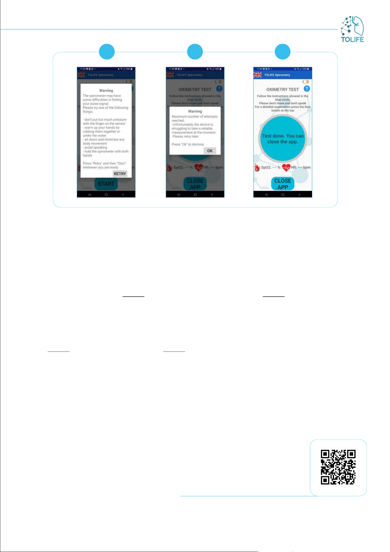
23
B CA
Figure 31: Oximetry test measurement failure.
SPIROMETRY MEASUREMENT GUIDELINES
Please follow these easy step-by-step guidelines to guarantee reliable spirometry measurements:
Insert the mouthpiece between your teeth and your lips around the mouthpiece. Your lips must grip
the mouthpiece firmly. Do not put your tongue in the mouthpiece. Do not bend your neck.
It is best to do the test standing or sitting upright (either one of the positions is correct).
Press the “START” button on the application and follow the displayed instructions (see the first part
of this document for more information about the Mini-Spirometer application).
Slowly inhale, taking in as much air as possible.
Blow with maximum force as possible until the “STOP” message appears on the screen.
Do not exhale slowly and at length. Do not cover the back of the Mini-Spirometer with the hand.
GLOSSARY
FEV1: medical parameter indicating the maximal expiratory volume of air a person can exhale from the
lungs in one second after taking as big a breath as possible.
HR: Heart rate (or pulse rate) is the number of times your heart beats per minute (bpm).
Oximetry: noninvasive method based on a light source and a photodetector for monitoring a person's blood
oxygen saturation (SpO
2
).
SpO
2
: blood oxygen saturation.
Scan to play the video

24
Funded by the European Union. Views and opinions expressed are however those of the author(s)
only and do not necessarily reflect those of the European Union or the European Health and Digital
Executive Agency (HADEA). Neither the European Union nor the granting authority can be held
responsible for them.
19.04.2024 ToLife - v1.1

25
PROJECT DETAILS:
Project number: 101057103
Project Full Title: Combining Artificial Intelligence and smart sensing TOward better
management and improved quality of LIFE in chronic obstructive
pulmonary disease
Project Acronym: TOLIFE
Topic: HORIZON-HLTH-2021-DISEASE-04-04
Type of action: HORIZON Research and Innovation Actions
Authority: European Health and Digital Executive Agency
Duration /Start-End date: 54 months / 1 Sept. 2022 - 28 Feb. 2027
Project Partners: 12
Project Coordinator: Alessandro Tognetti | University of Pisa
PARTNERS:
