Loading ...
Loading ...
User’s manual
The user manual apply to several models, for this reason
there may be some differences in the details given,
according to the type of the appliance.
1
Protecting the environment / advice for disposal
Packing
serves to protect the appliance during transportation and
recyclable materials have been used for packaging.
Corrugated board/cardboard (mainly from waste paper)
• shaped parts in PS (foamed CFC-free polystyrene)
• foils and bags in PE (polyethylene)
• strapping tapes in PP (polypropylene)
• Please hand over all packaging to the nearest official
collection point, so that all the different materials can be re-
used or recycled as far as possible and any illegal
depositing of such materials is thus avoided.
2
Deciding where to locate your appliance
In order to avoid any damage or injury to persons or things,
the appliance should be unpacked by two people and placed
in the chosen location
Before positioning it, check that your new appliance has
no visible outer damage.
On no account should you start up your appliance if it
is damaged.
Check the appliance carefully for:
• Damage to the packaging, which might indicate that the
appliance has been mishandled during transportation.
• Damage to the outer casing
• Any visible damage to the cable / plug
If in any doubt let, the customer service department check
the appliance.
It must at all costs be avoided, that any environmentally
damaging refrigerant leaks out by starting up the appliance.
4
Installing your appliance
3
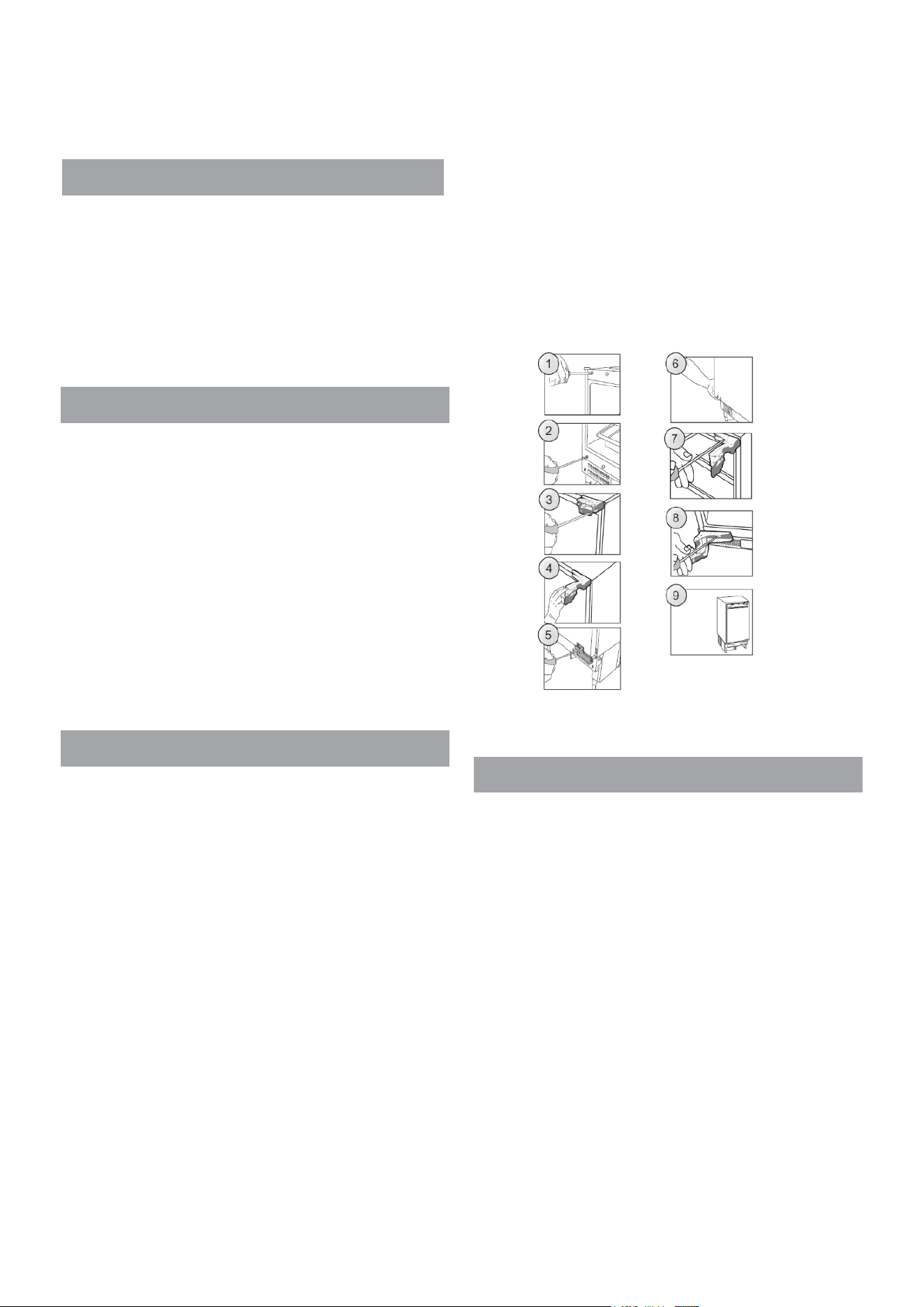
Reverse the door hinge
2
1. Unplug the appliance before reversing the door
opening
direction.
2. Remove food from the appliance.
3. Remove caps on the front of the refrigerator body
(Fig. 1, Fig 2).
4. Remove the two screws, which attach the upper
hinge to the appliance door (Fig. 3). Take special care
and hold the appliance door vertically.
5. Holding the door, swing the upper door hinge away
from the door using the other hand (Fig. 4).
Be especially careful during this step, as the hinge
may close and cause injury.
6. Remove the two screws, which attach the lower hinge
to the appliance door (Fig. 5). Take special care and
hold the appliance door with the other hand.
7. Holding the door, swing the lower door hinge away
from the door using the other hand, then detach the door
from the appliance body (Fig. 6).
8. Remove the two screws , which attach the upper
hinge to the body and the two screws holding the lower
hinge to the appliance body (Fig. 7).
9. Screw the upper and lower hinge on the opposite
side of the appliance body using suitable screws (Fig.
8). Upper hinge should be mounted on the other side of
the appliance as the lower hinge. The lower hinge
should be mounted on the other side of the appliance
as the upper hinge.
With the hinges open, hold the door parallel to the
appliance body and screw the hinges to the door using
suitable screws while taking proper care.
10。 Make sure that the door is properly aligned with
the appliance body (Fig.
9).
INSTALLATION OF THE APPLIANCE
Installation of the appliance should be performed by a
qualified installer. The appliance should be placed in
furniture case (Fig. 10). Once the appliance is placed
correctly, adjust the height of the appliance by turning
the 4 adjustable feet as appropriate. If necessary,
appliances should be braced with a bracket fixed by
screws and fitted in furniture (Fig. 11). There is a special
strip at the top of the appliance. Attach it to the
underside of the cabinet with appropriate screws
supplied with the assembly kit (Fig. 16).
Decorative strip must not block the vents located in the
bottom casing unit, the strip must be cut to size (Fig.
17). The depth of the bottom casing unit can be
adjusted by moving it forwards or backwards. Once
properly adjusted, tighten the mounting screws (located
in the openings on both sides of the casing unit) with a
cross-head screwdriver.
This will permanently attach the casing unit (Fig. 18).
Loading ...
Loading ...
Loading ...