Loading ...
Loading ...
Loading ...

5Section 2 — ASSembly & Set-Up
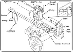
12. Pull out the vertical beam lock, rotate it back,
and pivot the beam to the horizontal position
until it locks. Be sure to avoid any possible
pinch points. See Figure 2-3
Vertical Beam Lock
Figure 2-3
WARNING! Take extra care when
raising and lowering the beam as it is
heavy. Having a second person assist
with raising or lowering the beam is
recommended. Be sure to keep hands
away from any possible pinch points.
13. Remove the wood between the wedge and
the end plate by cutting the cable tie that
secures it. Cut the strap near the hose on the
front of the cylinder that secures it to the
beam weld bracket. Be careful not to damage
the hose.
14. Disconnect the dislodger from the beam weld
bracket by removing the six hex screws. See
Figure 2-4.
Hex Screws
Hex Screws
Dislodger
Figure 2-4
15. Disconnect the log tray from the beam on the
control valve side by removing the two hex
washer screws that secure it to the beam weld
brackets and the two hex washer screws in the
beam. See Figure 2-5.
Hex
Washer
Screw
Log Tray
Beam
Figure 2-5
16. Lift and slide the cylinder up to the top of
beam and into the weld brackets. See Figure
2-6.
Cylinder
Weld Brackets
Figure 2-6
17. Attach the dislodger over the wedge assembly
and secure it to the weld brackets with the
hardware removed in step 14. See Figure 2-4.
NOTE: Lift up on the cylinder when installing
the hex screws.
NOTE: Once the six hex screws are tightened,
there may be a slight gap between the
dislodger and the weld brackets. This gap is
normal.
18. Reattach the log tray to the control valve side
of the beam, aligning the holes in the tray with
the holes in the beam and re-installing the
hardware removed in step 15. See Figure 2-7.
Hex
Washer
Screw
Beam
Log
Tray
Figure 2-7
19. Remove any staples on the bottom of the crate
that may puncture the tires.
20. Cut the metal strap securing the log splitter to
the bottom of the crate and remove the wood
under the engine and/or any other wood,
then roll the log splitter off the bottom of the
shipping crate.
21. The control handle is shipped hanging from
the valve on the handle link.
22. Remove the clevis pin and bow-tie cotter pin
from the control handle. See Figure 2-8.
Control Handle
Clevis
Pin
Bow-Tie
Cotter
Pin
Figure 2-8
23. Rotate the control handle into the operating
position and secure with the clevis pin and
bow-tie cotter pin removed in step 22. See
Figure 2-8.
Loading ...
Loading ...
Loading ...
