
Loading ...
Loading ...
Loading ...
8
SET-UP
NOTE: This Operator’s Manual covers several models. Not all
features in this manual are applicable to all models and the
model depicted may differ from yours.
NOTE: All references in this manual to the left or right side and
front or back of the tractor are from the operating position only.
Exceptions, if any, will be specified.
Refer to Figure 1 to match your transmission style; Foot Control
CVT (Continuously Variable Transmission) or CVT.
Foot Control CVT CVT
Figure 1
MANUALLY MOVING THE TRACTOR
1. Release parking brake, if activated.
2. Place the shift lever in the NEUTRAL (N) position.
INSTALL OPERATOR’S SEAT IF NECESSARY
Knob Adjust or Bolt Adjust
NOTE: The seat is shipped fastened to the tractor seat’s
pivot bracket with a cable tie OR mounted backward to the
pivot bracket.
To install the seat proceed as follows:
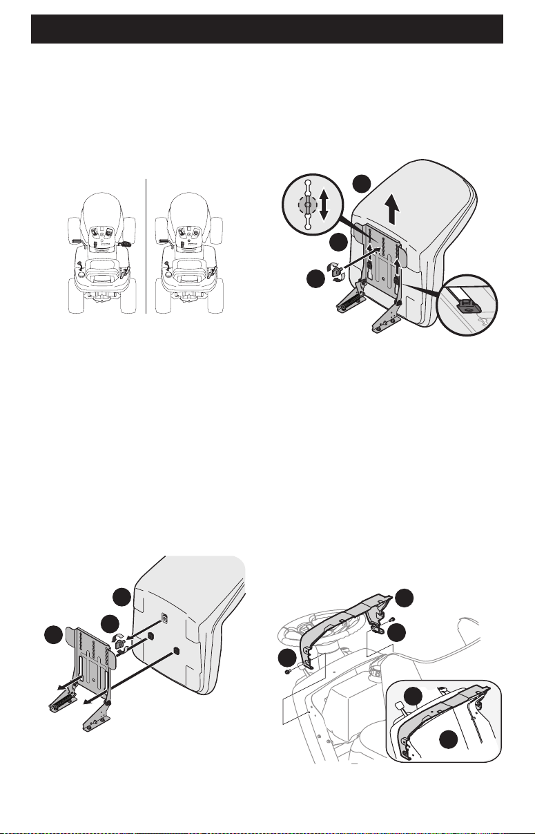
1. Remove the seat from its shipping position.
2. Remove the seat adjustment knob or 9/16 inch bolt (a) from
the bottom of the seat (b) (Figure 2).
a
b
c
Figure 2
3. Align the seat (b) over the seat pivot bracket (c) (Figure 2) and
fit the seat (b) onto the seat pivot bracket (c) inserting the
two tabs on the seat (b) bottom into the wide opening of the
slots on the seat pivot bracket (c).
4. Slide the seat (b) rearward in the seat pivot bracket (c), lining
up one of the slots in the seat pivot bracket (c) with the hole
in the center rear of the seat (b) base (Figure 3).
a
b
c
Figure 3
NOTE: Be certain the two seat tabs engage the seat pivot bracket
as shown in the bottom right inset of Figure 3.
5. Select the desired position for the seat (b), and secure with
the adjustment knob or 9/16 inch bolt (a) removed in Step 2
(Figure 3).
DASH SHROUD IF EQUIPPED
1. If the dash shroud (a) was shipped loose, the hardware for
attaching the dash shroud (a) is shipped attached to the dash
shroud (a). Remove the two bolts (b) from the dash shroud
(a) (Figure 4).
2. Mount the dash shroud (a) and align the mounting holes
between the top of the dash and the dash shroud (Figure 4).
3. Secure the dash shroud (a) to the dash (c) with the bolts (b)
removed in Step 1 (Figure 4).
a
b
b
c
a
Figure 4
Loading ...
Loading ...
Loading ...