
Loading ...
Loading ...
Loading ...
26
PRODUCT CARE
5. To lower the front of the deck, loosen the outer nut then
loosen (thread outward) the inner nut, away from the front
hanger bracket (Figure 25). When proper adjustment is
achieved, re-tighten the outer nut.
Figure 25
ADJUSTING THE DECK WHEELS
WARNING
Keep hands and feet away from the discharge opening of
the cutting deck.
NOTE: The deck wheels are an anti-scalp feature of the deck and
are not designed to support the weight of the deck.
The deck wheels should be approximately 1⁄4-1⁄2 inch (6.35-
12.7 mm) above the ground when the deck is set in the desired
height setting. To adjust the deck wheels see the Set-Up section
for instructions.
SERVICE
Electrical System
A fuse is installed to protect the tractor’s electrical system from
damage caused by excessive amperage. Always use the same
capacity fuse for replacement. If the electrical system does not
function, check for a blown fuse.
If you have a recurring problem with blown fuses, have
the tractor’s electrical system checked by your authorized
service dealer.
Relays and Switches
There are several safety switches in the electrical system. If a
function of the safety interlock system described earlier is not
functioning properly, have the electrical system checked by your
authorized service dealer.
Parking Brake Adjustment
If the tractor does not come to a complete stop when the brake
pedal is completely depressed, or if the tractor’s rear wheels
can roll with the parking brake applied, the brake is in need
of adjustment. See your authorized service dealer to have the
brake adjusted.
WHEEL ALIGNMENT
If your tractor pulls to one side or is out of alignment, a wheel
alignment might be necessary. Contact an authorized service
dealer to have the wheels properly aligned.
DECK REMOVAL
WARNING
Use caution to avoid pinching your fingers when rolling
the belt off the PTO pulley.
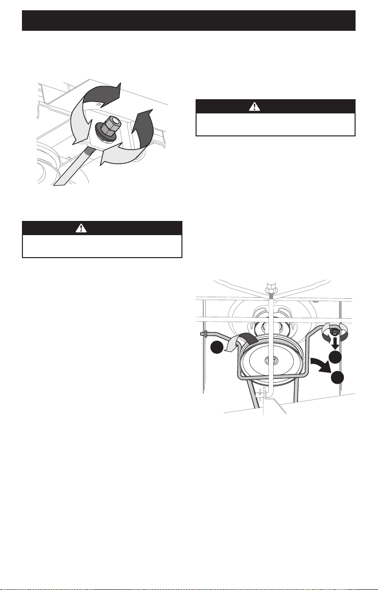
To remove the cutting deck, proceed as follows:
1. Move the tractor to a level surface, disengage the PTO, stop
the engine and ENGAGE the parking brake.
2. Lower the deck by moving the deck lift lever into the bottom
notch on the right fender.
3. Remove the belt-keeper rod (a), from around the tractor’s
engine pulley, by removing the self-tapping screw (b) that
secures it (Figure 26).
NOTE: Make a note what hole the other end of the belt-keeper
rod is inserted in for reinstallation purposes.
4. Remove the belt (c) from around the tractor’s engine pulley
and idler pulley(s) (Figure 26).
a
b
c
Figure 26
5. Looking at the cutting deck from the left side of the tractor,
locate the bow-tie pin (a) that secures the deck support rod
(b) on the rear left side of the deck (Figure 27 on page 27).
Remove the bow-tie pin (a) that secures the deck support
rod (b), and carefully remove the deck support from the deck
lift arm.
Loading ...
Loading ...
Loading ...