Loading ...
Loading ...
Loading ...
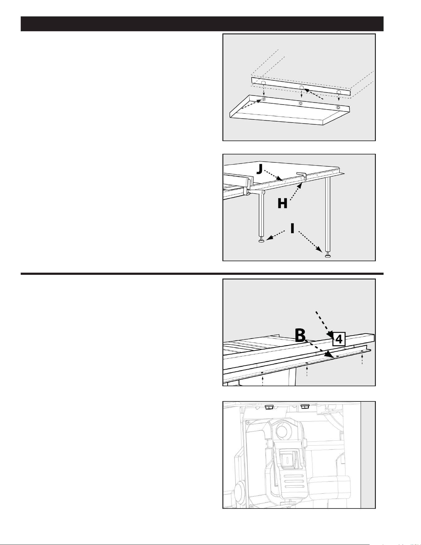
FIGURE 12
FENCE GUIDE
ASSEMBLY
FIGURE 13
FIGURE 14
FIGURE 11
FENCE GUIDE AND POWER
CONTROL BOX
1. Attach the fence guide to the front rail using four (for
30” versions) six (for 52” versions) 1/4-20 x 1/2inch hex
button head screws and ¼-inch spring washers through
the holes (B) on the bottom side of the front rail.
2. A align the two holes in the power control box bracket
with the holes underneath the front rail, shown in Figure
14 (C), located on the left side of the saw. Secure the
power control box to the front rail using two 1/4-20 x
1/2-inch hex head cap screws with spring washers .
G
F
4. Feed the #10-32 X 1 1/4” screws with #10 at washers
(E) through the drilled holes from the outside, then
assemble the nuts onto the screws and tighten.
5. Loosely assemble three 5/16-18 x 7/8” screws with
spring washers, at washers and nuts (F) into the three
holes into the side of the extension wing as shown.
(Fig. 11)
6. Carefully lower the slotted steel angle table bracket (G)
down onto the screws on the extension wing. Tighten
the screws after the wood table is leveled with the
extension wing.
7. Using the rail alignment gauge (H) adjust the feet in the
legs (I) so the top of the table is at the proper distance
from the rail.
8. Drill ¼ inch holes through the rail holes (J) into the
wood table on the front and back rails. (Fig. 12)
9. Fasten wood table to rails with ¼-20 X 1 ½” hex head
screws for rear rail and ¼-20 X 1 ½” at head screws
for front rail, at washers, and nuts.
14 15
Loading ...
Loading ...
Loading ...