Loading ...
Loading ...
Loading ...
8
9
OPERATION
WARNING
To reduce the risk of injury, always
wear proper eye protection marked
to comply with ANSI Z87.1.
When working in dusty situations, wear appro-
priate respiratory protection or use an OSHA
compliant dust extraction solution.
Keep hands and body out of the path of the saw
blade. Contact with blade will result in serious
injury. Check guarding system to make sure it is
functioning correctly. Do not operate saw without
guards in place. Do not perform any operation
freehand. Never reach around saw blade. Turn
off tool and wait for saw blade to stop before
moving workpiece or changing settings. Tighten
all adjustments prior to use.
Cut Line Indicator
The cut-line indicator shines down the blade, casting
a shadow where the blade will meet the workpiece.
No calibration/adjustments will be needed as the
shadow will always be true to the blade location.
Use the cut-line indicator switch to turn on the light
before making a cut. The light will go off automatically
about 9 seconds after use.
WARNING
To reduce the risk of injury, do not
rely on the brake as a safety fea-
ture. Always wait until the blade
stops completely before allowing anything near
the blade.
To reduce the risk of injury, make sure all adjust-
ments are securely locked before making a cut.
Starting and Stopping the Tool
Always hold the trigger handle fi rmly because the
starting and stopping action of the motor may cause
the handle to move up or down slightly. WARNING!
Always press down miter lock lever and tighten all
adjustments prior to use. WARNING! Ensure hands
are out of the No Hands Zone.
1. To start the motor, push down the trigger lock and
pull the trigger.
2. To stop the motor, release the trigger. The elec-
tric brake will stop the blade in about 4 seconds.
WARNING! The brake is not a substitute for the
guards and could fail; always wait for the blade to
stop completely before removing the blade from
the workpiece. If the brake fails to stop the blade or
misses frequently, return the tool to a MILWAUKEE
service facility for repair.
Making a Chop Cut
Cut workpieces with chop cuts whenever possible.
Only use sliding cuts (cross cuts) when necessary.
1. Select the desired angles and adjust the fences to
ensure fence hand holds are positioned to keep
hands out of the No Hand Zone.
2. Place the workpiece on the turntable and line up
the cut.
3. Insert battery pack.
4. Support the workpiece using any of the methods
described in "Support the Workpiece Properly".
5. WARNING! Keep hands out of the No Hands
Zone at all times during use. Contact with blade
will result in serious injury.
6. Start the motor. Wait a few seconds for the blade to
reach full speed. Then gently lower the saw head
into the workpiece all the way through the cut.
WARNING! Do not allow the blade to contact the
workpiece while tool is ramping up.
7. Always allow the saw to do the work. Forcing the
tool may stall or overheat the motor.
8. After the cut is complete, release the trigger and
wait for the blade to stop completely. Raise the
saw head and remove the workpiece. WARNING!
If small cut-off pieces get caught in the guard area,
remove battery pack before clearing.
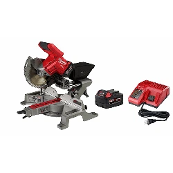
Making a Sliding Cut (Cross Cut)
Wider workpieces can be cut using the sliding
mechanism. Always use chop cut whenever possible.
4
2
3
1
1. Make sure that the slide rail transport lock is loose,
and the saw head moves freely back and forth.
2. Select the desired angles and adjust the fences to
ensure fence hand holds are positioned to keep
hands out of the No Hand Zone.
3. Place the workpiece on the turntable and line up
the cut.
4. Insert battery pack.
5. Support the workpiece using any of the methods
described in "Support the Workpiece Properly".
6. WARNING! Keep hands out of the No Hands
Zone at all times during use. Contact with blade
will result in serious injury.
7. Raise saw head and pull it out OVER the work-
piece WITHOUT cutting.
8. Start the motor. Wait a few seconds for the blade
to reach full speed. WARNING! Do not allow
the blade to contact the workpiece while tool is
ramping up.
9. Press down on saw head.
10. Push saw through the cut. WARNING! Return
saw head to the full rear position after each
crosscut operation.
11. After the cut is complete, release the trigger and
wait for the blade to stop completely. Raise the
saw head and remove the workpiece. WARNING!
If small cut-off pieces get caught in the guard
area, remove battery pack before clearing.
APPLICATIONS
WARNING
Do not cut stone, brick, concrete,
magnesium, or ferrous metals
(iron, steel, stainless steel, or alloys of these
metals) with this saw.
Do not use abrasive wheels with this saw.
Dust created by cutting these materials and/or
using abrasive cut-off wheels can jam the blade
guard and possibly cause personal injury.
Recommended Materials and Applications
The following materials can be cut with the compound
sliding miter saw. There are many types of saw
blades available. Always use the proper blade for the
particular material and application. Use only 7-1/4"
sliding miter saw blades rated at least 5000 RPM.
• Wood - solid wood, plywood, particle board, MDF
(medium density fi berboard), HDF (high density
fi berboard), melamine laminated particle board,
formica laminates, hardboard (masonite).
• Plastics - PVC, CPVC, ABS, solid surfacing materi-
als (such as Corian
®
), and other plastic materials.
When cutting plastic, avoid overheating the blade
and blade teeth to prevent melting the workpiece.
• Nonferrous Metals - aluminum, brass, copper, and
other non-ferrous materials.
Cutting Non-Square Materials
Cutting Round (Cylindrical) Materials
"V" shaped blocks can be used to support round
materials like closet rod and plastic pipe.
Aluminum Sash and Other
Channel Type and Materials
Aluminum sash material can be supported with blocks
to prevent it from deforming while it is being cut.
Clamp
Fence
Table
Wood support
block
Aluminum
material
Wood support
block
Miter Range Miter Detents (Stops)
0° to 45° Left
0° to 45° Right
0°, 15°, 22.5°, 31.62°, 45° Left
0°, 15°, 22.5°, 31.62°, 45° Right
Bevel Range Bevel Detents (Stops)
0° to 48° Left
0° to 48° Right
0°, 45° Left
0°, 45° Right
Base Molding
Capacity
Nested Crown
Capacity
3-1/2" at 0°
3-1/2" at 45° Left
3-1/2" at 45° Right
3-5/8"
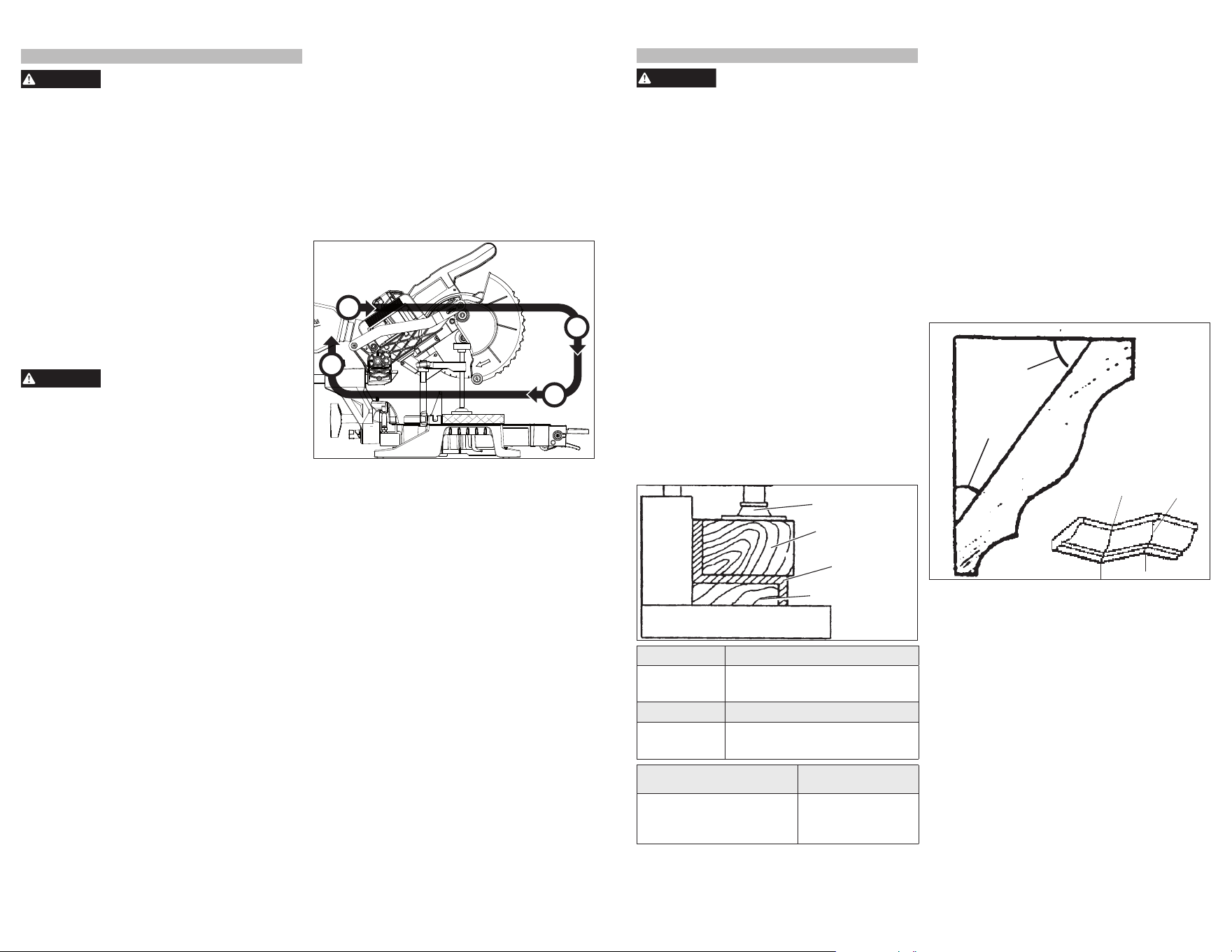
Two Methods for Cutting Crown Molding
The angles created on a piece of crown molding that
fi ts fl at against the ceiling and wall will, when added
together, equal 90° (A + B = 90°).The most common
crown molding angles are :
52
°
/38
°
: A 52° angle against the ceiling (A) and a 38°
angle against the wall (B). The miter saw has spe-
cial miter settings at 31.6° left and right and a bevel
setting at 33.9° to use when cutting 52°/ 38° crown
molding fl at on the miter saw table. These settings
are identifi ed with a diamond mark.
45
°
/45
°
: A 45° angle against the ceiling (A) and a 45°
angle against the wall (B). The miter saw has special
miter settings at 35.3° left and right and a bevel set-
ting at 30° to use when cutting 45°/ 45° crown fl at
on the miter saw table. These settings are identifi ed
with a black circle.
NOTE: Even though all of these angles are standard,
rooms are very rarely constructed so the corners
are exactly 90°. You will need to “fi ne tune” these
settings and make necessary adjustments to the
cutting angles.
Ceiling
Wall
Angle B
Angle A
Inside
corner
Outside
corner
Cutting Crown Molding Flat on the
Miter Saw Table
The advantage of cutting crown molding fl at on the
table is that it is easier to secure the molding at the
correct cutting position. Also larger pieces of crown
molding may be cut lying fl at on the miter saw table.
1. Set the bevel and miter angles using the Crown
Molding Miter Angles chart. Tighten the miter lock
lever and the bevel adjustment lever.
2. Using the Positioning section below, correctly
positions the molding.
NOTE: Always make a test cut on scrap material
to confi rm all angles are correct.
3. Make the cut according to "Making a Chop Cut".
Cutting Crown Molding Angled Against
the Fence (Nested – in position)
Bevel settings are not required when cutting crown
molding against the fence. Small changes in the miter
angle can be made without aff ecting the bevel angle.
When using this method the saw can be quickly and
easily adjusted for corners that are not 90° (square).
Loading ...
Loading ...
Loading ...