Loading ...
Loading ...
4
5
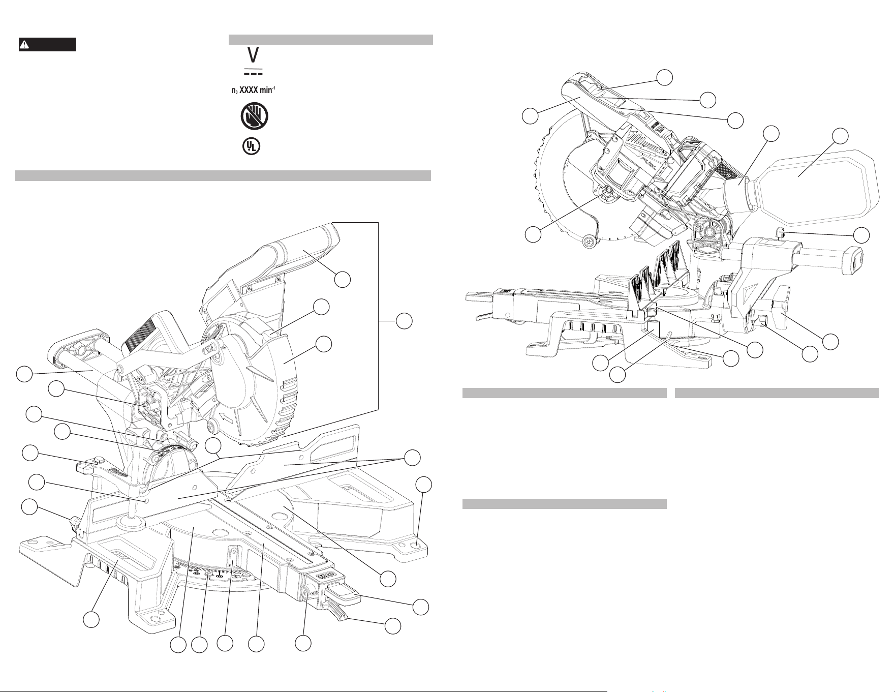
28. Dust bag
29. Slide rail lock
30. Bevel knob
1. Saw head
2. Trigger handle
3. Light
4. Lower guard
5. Fence hand holds
6. Fences (2)
7. Mounting holes (4)
8. Turntable
9. Miter lock lever
10. Detent lever
11. Detent override knob
12. Kerf plate
13.Miter angle pointer
FUNCTIONAL DESCRIPTION
•
WARNING
Some dust created by power sanding,
sawing, grinding, drilling, and other
construction activities contains chemicals known to
cause cancer, birth defects or other reproductive harm.
Some examples of these chemicals are:
• lead from lead-based paint
• crystalline silica from bricks and cement and other
masonry products, and
• arsenic and chromium from chemically-treated lumber.
Your risk from these exposures varies, depending on
how often you do this type of work. To reduce your
exposure to these chemicals: work in a well ventilated
area, and work with approved safety equipment, such
as those dust masks that are specially designed to
fi lter out microscopic particles.
SYMBOLOGY
Volts
Direct Current
No Load Revolutions per Minute (RPM)
No Hands Zone - Keep hands out of
the No Hands Zone at all times during
use. Contact with blade will result in
serious injury.
C
US
UL Listing for Canada and U.S.
14.Miter angle scale
15. No Hands Zone circle
16.Carrying handles
17. Fence lock knobs (2)
18.Face board mounting holes (4)
19. Workpiece clamp
20. Bevel angle scale
21. Bevel angle pointer
22. Head lock-down pin
23.Slide rails
24. Trigger
25. Trigger lock
26. Cut-line indicator switch (not shown)
27. Dust chute
1
15
10
6
5
2
16
3
18
21
14
4
11
7
8
12
13
17
19
20
22
23
9
SPECIFICATIONS
Cat. No. ..................................................... 2733-20
Volts.............................................................. 18 DC
Battery Type .................................................M18™
Charger Type................................................M18™
Recommended Ambient
Operating Temperature ..................... 0°F to 125°F
No Load RPM ..................................................5000
Arbor Size ......................................................... 5/8"
Blade Size ..................................................... 7-1/4"
Blade Thickness (Kerf) ............................. Max 1/8"
Weight ..........................................................28 lbs.
CAPACITIES
Miter Cuts
Max Height ..................................................... 2.2"
Max Width at 0°
Miter...................................... 8.3"
Max Width at 45° Miter .................................. 5.8"
Bevel Cuts
Max Height at 0° Bevel ................................... 2.2"
Max Height at Left 45° Bevel .......................... 1.6"
Max Height at Right 45° Bevel ....................... 0.8"
Compound Cuts (45° Miter and 45° Bevel)
Left ..............................................5.9" W at 1.6" H
Right ............................................5.9" W at 0.8" H
Workpiece Vertical Against Fence
0° Miter / 0° Bevel ........................3.6" W at 0.9" H
Left 45° Miter / 0° Bevel ...............3.6" W at 0.8" H
Right 45° Miter / 0° Bevel ............3.6" W at 0.7" H
ASSEMBLY
Transporting and Storing
Always lock the saw head and slide rails before
transporting and storing the tool. Only carry tools by
the carrying handles.
Saw Head
To lock, press and hold down the saw head and then
push in the lock-down pin.
To unlock, press and hold down the saw head and
pull out the lock-down pin. Raise the saw head.
Slide Rails
To unlock, loosen the slide rail lock by turning it
counterclockwise.
To lock, slide the saw head forward and tighten the
slide rail lock by turning it clockwise.
Mounting the Miter Saw
To prevent the tool from sliding, falling or tipping
from a raised work surface during operation, the saw
should be mounted to a supporting surface such as
a level, sturdy work table, bench, or miter saw stand.
Position the saw and workbench to allow adequate
room for cross-cutting long workpieces. To mount
the saw to a fl at surface, insert fasteners through
the holes in the corners of the saw base and secure.
Follow manufacturer instructions when mounting to
a miter saw stand.
31. 0° stop pin
32. Hand stop
33. Wrench storage (not shown)
34. 6 mm Hex Wrench
35. Workpiece clamp sockets (2)
36. Spindle lock
37. Handle
25
33
35
27
26
24
29
37
36
34
32
30
28
31
Loading ...
Loading ...
Loading ...