Rev. V11222023DT (DZUG0268)
Important Safety & Warning Precautions
Make sure to read this user’s guide and
Caution
: The screen’s Black Top Drop is already set to its maximum drop distance. There is NO extra Black
Top Drop in the roller. Please be aware of this as it will void your warranty with AKIA Screens. Unapproved
changes or m
odifications (except for cutting the power cord for hardwire installations) to this unit are prohibited
and will void your warranty. For more information, please contact our Technical Support Department.
AKIA
allows a 1.5% tolerance within the viewing sur
materials over time.
Please retain this user’s guide for future reference.
To avoid damaging the unit, do not use with any unauthorized accessories not recommended by the
manufacturer.
Handle the unit care
fully during transportation to avoid any damages.
To ensure safe and reliable operation, direct connection to a properly grounded power source is advised.
The power outlet supplying power to the unit should be close to the unit and easily accessible.
Do no
t install the unit on uneven or inclined surfaces.
Do not put heavy objects on the power cord and position it properly to avoid creating a trip obstacle.
Never overload the power cord to prevent an electric shock or fire due to a loose contact or a short
circuit.
There are not user serviceable parts in this unit. Do not attempt to disassemble this unit by yourself. No
one except authorized technicians can open and make repairs to this unit.
Make sure the power source this unit is connected to has a
If there is need to use an extension cord, make sure the cord has an equal rating as the appliance to avoid
overheat.
Do not handle the power plug when your hands are wet or your feet are in contact with water.
Do not use this unit
under the following circumstances.
Disconnect the power cord under the conditions of heavy rain, wind, thunder or lightning.
Avoid direct Sunshine, rain shower and moisture.
Keep away from fire sources and high temperature to prevent this device from
Cut off the power supply first before transportation or maintenance.
Fully disconnect from the power supply when the unit is not in use for a long period of time, as should
be done with any other electric household appliance.
To avoid possible
injury and/or an electric shock, do not attempt to use the screen if there is obvious
damage or if there are any evident broken parts.
1
Motorized Series
Electric Wall/Ceiling Projection Screen
User’s Guide –
E type (RC1) V1.0
Important Safety & Warning Precautions
Make sure to read this user’s guide and
follow the procedures below.
: The screen’s Black Top Drop is already set to its maximum drop distance. There is NO extra Black
Top Drop in the roller. Please be aware of this as it will void your warranty with AKIA Screens. Unapproved
odifications (except for cutting the power cord for hardwire installations) to this unit are prohibited
and will void your warranty. For more information, please contact our Technical Support Department.
allows a 1.5% tolerance within the viewing sur
face for expansion and contraction of the screen
Please retain this user’s guide for future reference.
To avoid damaging the unit, do not use with any unauthorized accessories not recommended by the
fully during transportation to avoid any damages.
To ensure safe and reliable operation, direct connection to a properly grounded power source is advised.
The power outlet supplying power to the unit should be close to the unit and easily accessible.
t install the unit on uneven or inclined surfaces.
Do not put heavy objects on the power cord and position it properly to avoid creating a trip obstacle.
Never overload the power cord to prevent an electric shock or fire due to a loose contact or a short
There are not user serviceable parts in this unit. Do not attempt to disassemble this unit by yourself. No
one except authorized technicians can open and make repairs to this unit.
Make sure the power source this unit is connected to has a
continuous power flow.
If there is need to use an extension cord, make sure the cord has an equal rating as the appliance to avoid
Do not handle the power plug when your hands are wet or your feet are in contact with water.
under the following circumstances.
Disconnect the power cord under the conditions of heavy rain, wind, thunder or lightning.
Avoid direct Sunshine, rain shower and moisture.
Keep away from fire sources and high temperature to prevent this device from
Cut off the power supply first before transportation or maintenance.
Fully disconnect from the power supply when the unit is not in use for a long period of time, as should
be done with any other electric household appliance.
injury and/or an electric shock, do not attempt to use the screen if there is obvious
damage or if there are any evident broken parts.
www.akiascreens.com
Motorized Series
Electric Wall/Ceiling Projection Screen
USER’S GUIDE
E type (RC1) V1.0
: The screen’s Black Top Drop is already set to its maximum drop distance. There is NO extra Black
Top Drop in the roller. Please be aware of this as it will void your warranty with AKIA Screens. Unapproved
odifications (except for cutting the power cord for hardwire installations) to this unit are prohibited
and will void your warranty. For more information, please contact our Technical Support Department.
face for expansion and contraction of the screen
To avoid damaging the unit, do not use with any unauthorized accessories not recommended by the
To ensure safe and reliable operation, direct connection to a properly grounded power source is advised.
The power outlet supplying power to the unit should be close to the unit and easily accessible.
Do not put heavy objects on the power cord and position it properly to avoid creating a trip obstacle.
Never overload the power cord to prevent an electric shock or fire due to a loose contact or a short
There are not user serviceable parts in this unit. Do not attempt to disassemble this unit by yourself. No
continuous power flow.
If there is need to use an extension cord, make sure the cord has an equal rating as the appliance to avoid
Do not handle the power plug when your hands are wet or your feet are in contact with water.
Disconnect the power cord under the conditions of heavy rain, wind, thunder or lightning.
Keep away from fire sources and high temperature to prevent this device from
overheating.
Fully disconnect from the power supply when the unit is not in use for a long period of time, as should
injury and/or an electric shock, do not attempt to use the screen if there is obvious
Rev. V11222023DT (DZUG0268)
NOTE:
This equipment has been tested and found to comply with the limits for a Class B digital device, pursuant to
15 of the FCC Rules.
These limits are designed to provide reasonable protection against harmful interference in a residential
installation. This equipment generates and can radiate radio frequency energy and, if not installed and used in
accordance
with the instructions, may cause harmful interference to radio communications.
However, there is no guarantee that the interference will not occur on a particular installation. If this equipment
causes harmful interference to radio or television reception
off and on, the user is encouraged to try to correct the interference by one or more of the following measures.
Reorient or relocate the receiving antenna of the device which may be causing the interferenc
Increase the separation between the screen and the device’s receiver.
Connect the equipment into a different power outlet other than the device.
Pre-Installation
1.
Carefully unpack the screen.
2.
Always handle the screen in a leveled position
on a clean surface.
3.
In order to protect the screen from exposure to
stains, keep the screen out of contact with
foreign particles such as dust, sawdust, and/or
liquids.
NOTE
Regardless of the mounting method, the screen should be securely supported so that the vibration or pulling on
the viewing surface will not cause the casing to become loose or fall. Includ
complimentary and may not be appropriate for all mounting surfaces. Use appropriate anchors to safely secure
the screen to the mounting surface or consult with a professional installer.
Hardware and
Controls Accessories
Please make sure all parts listed below are included before proceeding with the installation.
A.
M
5x60
Screw
x
6
D. M6.5 eyebolt screw x2
E
2
This equipment has been tested and found to comply with the limits for a Class B digital device, pursuant to
These limits are designed to provide reasonable protection against harmful interference in a residential
installation. This equipment generates and can radiate radio frequency energy and, if not installed and used in
with the instructions, may cause harmful interference to radio communications.
However, there is no guarantee that the interference will not occur on a particular installation. If this equipment
causes harmful interference to radio or television reception
, which can be determined by turning the equipment
off and on, the user is encouraged to try to correct the interference by one or more of the following measures.
Reorient or relocate the receiving antenna of the device which may be causing the interferenc
Increase the separation between the screen and the device’s receiver.
Connect the equipment into a different power outlet other than the device.
Carefully unpack the screen.
Always handle the screen in a leveled position
In order to protect the screen from exposure to
stains, keep the screen out of contact with
foreign particles such as dust, sawdust, and/or
Regardless of the mounting method, the screen should be securely supported so that the vibration or pulling on
the viewing surface will not cause the casing to become loose or fall. Includ
ed mounting screws are
complimentary and may not be appropriate for all mounting surfaces. Use appropriate anchors to safely secure
the screen to the mounting surface or consult with a professional installer.
Controls Accessories
List
Please make sure all parts listed below are included before proceeding with the installation.
B.
M1
2
Dry
-
wall anchor
x
6
C. Snap link x2
E
.
Wall/Ceiling mount bracket x2
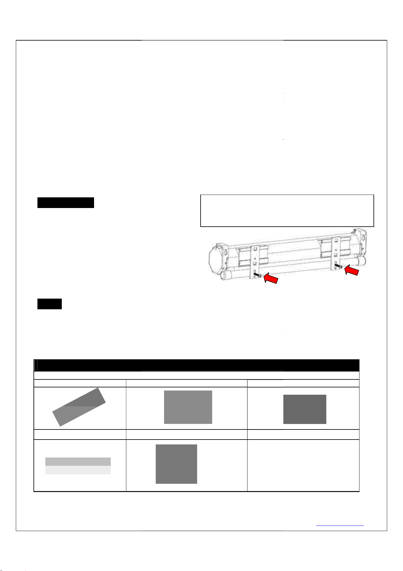
Please note: Before fully operating the screen. Remove
the shipping brackets from the housing and t
bar by loosening the 2
screws.
www.akiascreens.com
This equipment has been tested and found to comply with the limits for a Class B digital device, pursuant to
Part
These limits are designed to provide reasonable protection against harmful interference in a residential
installation. This equipment generates and can radiate radio frequency energy and, if not installed and used in
with the instructions, may cause harmful interference to radio communications.
However, there is no guarantee that the interference will not occur on a particular installation. If this equipment
, which can be determined by turning the equipment
off and on, the user is encouraged to try to correct the interference by one or more of the following measures.
Reorient or relocate the receiving antenna of the device which may be causing the interferenc
e.
Connect the equipment into a different power outlet other than the device.
Regardless of the mounting method, the screen should be securely supported so that the vibration or pulling on
ed mounting screws are
complimentary and may not be appropriate for all mounting surfaces. Use appropriate anchors to safely secure
Please make sure all parts listed below are included before proceeding with the installation.
C. Snap link x2
Please note: Before fully operating the screen. Remove
the shipping brackets from the housing and t
he weight
screws.
Rev. V11222023DT (DZUG0268)
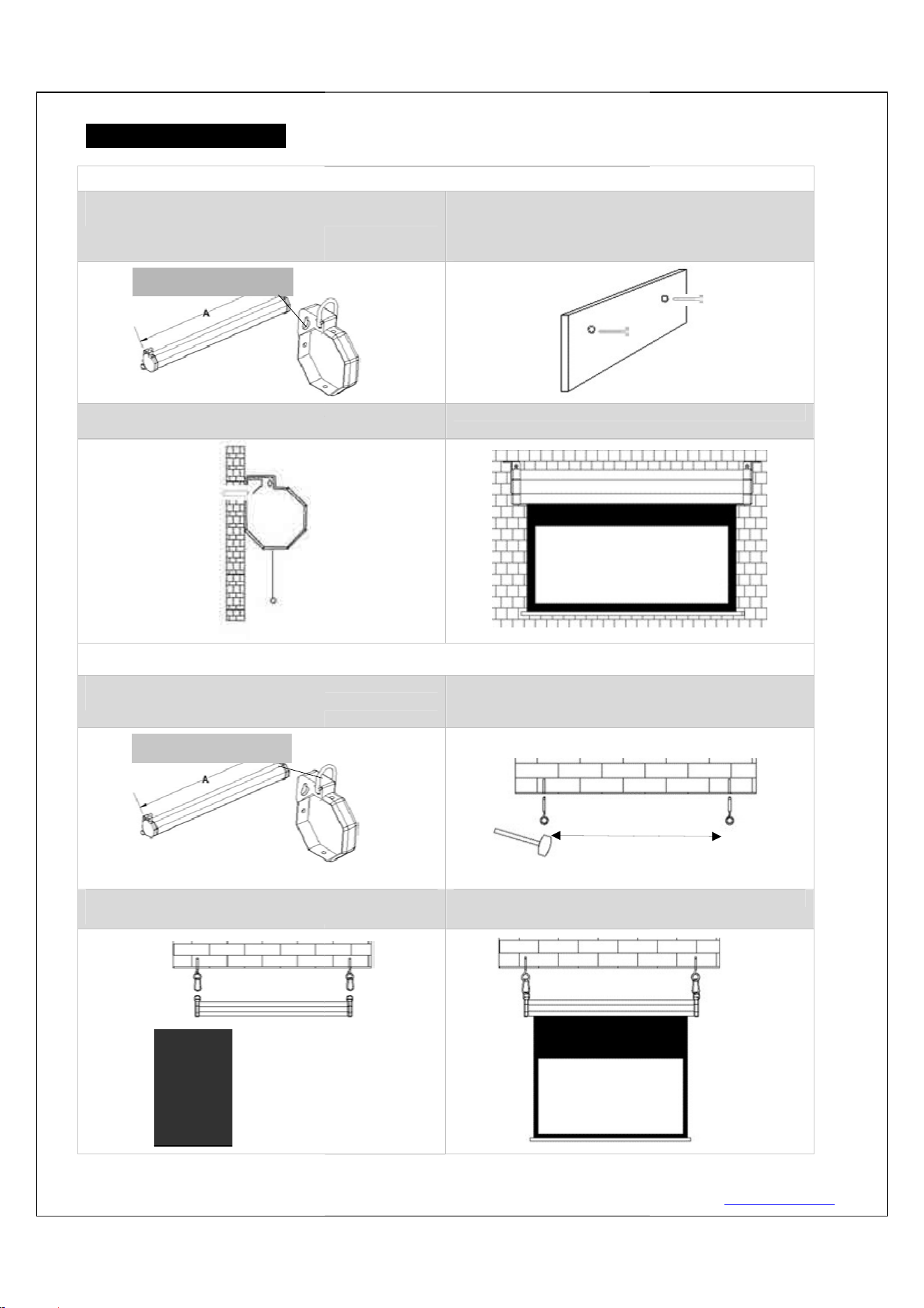
Installation Instructions
For installation assistance, please consult a professional Installer. AKIA Screens is not liable for faulty installations.
A. Wall Mount
Step 1: Measure and mark the (A) distance between the
two holes on each bracket.
Step 3: Hang the screen by aligning the end cap holes to
the M5x60 screws.
B. Ceiling Mount
Step 1: Measure and mark the (A) distance between the
two loops on each bracket.
Step 3:
Attach the snap link through the eyebolt and
connect it to the loop on the screen’ end cap.
Side View
3
For installation assistance, please consult a professional Installer. AKIA Screens is not liable for faulty installations.
Step 1: Measure and mark the (A) distance between the
Step 2:
Drill a hole for each screw hole on the marked
areas. Insert a dry-wall anchor
into the wall. Then screw
the M5x60 Screw in each
dry
about 1/8” of an inch.
Step 3: Hang the screen by aligning the end cap holes to
Step 4: please make sure the screen is
Step 1: Measure and mark the (A) distance between the
Step 2: Drill a hole on all marked areas and insert
theM6.5 eyebolt
screw into the hole, then screw up with
hammer.
Attach the snap link through the eyebolt and
connect it to the loop on the screen’ end cap.
Step 4: please make sure the screen is
Wall
A
Ceiling
www.akiascreens.com
For installation assistance, please consult a professional Installer. AKIA Screens is not liable for faulty installations.
Drill a hole for each screw hole on the marked
into the wall. Then screw
dry
-wall anchor in leaving
Step 4: please make sure the screen is
on a line.
Step 2: Drill a hole on all marked areas and insert
screw into the hole, then screw up with
Step 4: please make sure the screen is
on a line.
Rev. V11222023DT (DZUG0268)
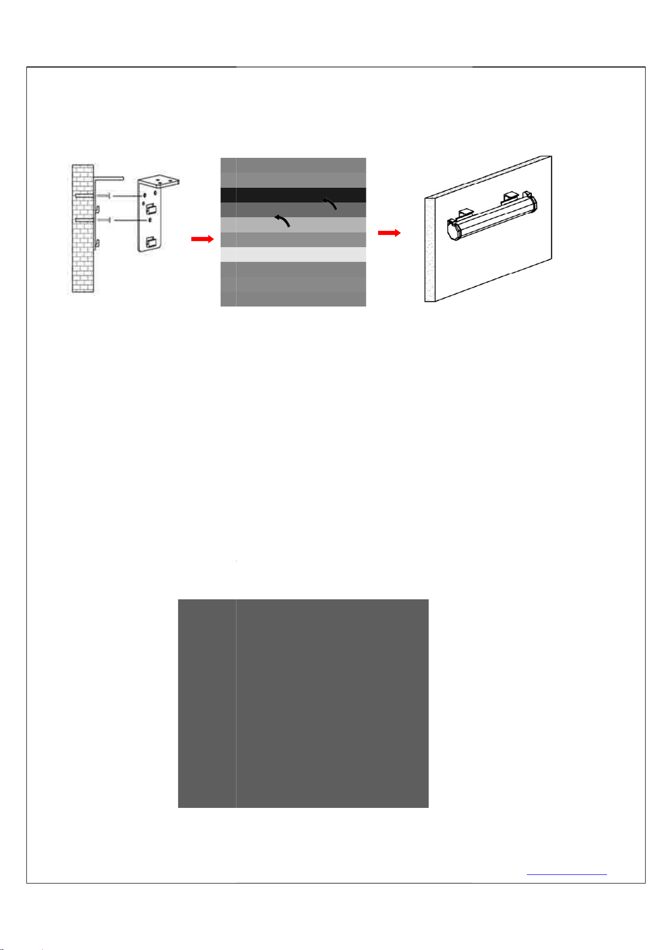
This mount method allows
1.
Determine where the screen will be installed. Then, measure and mark the distance between the top
and bottom screw holes from each
2.
Drill a hole on all marked points and install the brackets with the
screw (A
), Make sure both brackets are properly leveled.
3.
Hang the screen by placing the
4. After m
aking sure the screen is secured, you can slide it to left / right around 80mm to properly
center it in bracket’s position.
※
Sliding bracket at the back of the screen support customer to adjust position a little bit while
screen has position issue, it can s
back of the screen. (
Refer below picture)
※
Two or more people are required while one holds the screen in place.
※
Noticed of sliding bracket application:
Please make sure the adjustment of sliding
bracket, it allows customer to slide the casing a little bit to adjust the position to the correct one
while the bracket got tolerance of installation. (A = 80mm)
Front view of bracket (A)
4
This mount method allows
the screen to slide horizontally.
Determine where the screen will be installed. Then, measure and mark the distance between the top
and bottom screw holes from each
Wall/Ceiling mount bracket (E).
Drill a hole on all marked points and install the brackets with the
dry-
wall anchor
), Make sure both brackets are properly leveled.
Hang the screen by placing the
lower
“catch” located on the back over the brackets
aking sure the screen is secured, you can slide it to left / right around 80mm to properly
center it in bracket’s position.
Sliding bracket at the back of the screen support customer to adjust position a little bit while
screen has position issue, it can s
lide around 80mm from the center of sliding bracket at the
Refer below picture)
Two or more people are required while one holds the screen in place.
Noticed of sliding bracket application:
Please make sure the adjustment of sliding
bracket is within 80mm range from the center of
bracket, it allows customer to slide the casing a little bit to adjust the position to the correct one
while the bracket got tolerance of installation. (A = 80mm)
www.akiascreens.com
the screen to slide horizontally.
Determine where the screen will be installed. Then, measure and mark the distance between the top
wall anchor
(B), M5x60
“catch” located on the back over the brackets
upper “catch”.
aking sure the screen is secured, you can slide it to left / right around 80mm to properly
Sliding bracket at the back of the screen support customer to adjust position a little bit while
lide around 80mm from the center of sliding bracket at the
bracket is within 80mm range from the center of
bracket, it allows customer to slide the casing a little bit to adjust the position to the correct one
Rev. V11222023DT (DZUG0268)
Screen operation
Electric Current
: Depending on your region, the screen will operate in either
1. After ensuring the power outlet & screen are compatible (voltage), plug the power cord into the power
outlet.
2. Once the screen has power, you’ll be able to control it using any of the
3
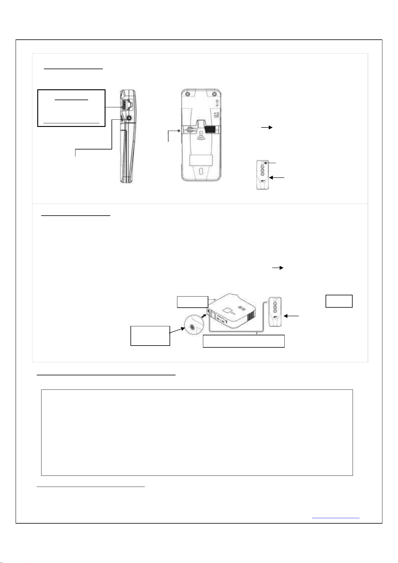
Ways to control your Evanesce Tab
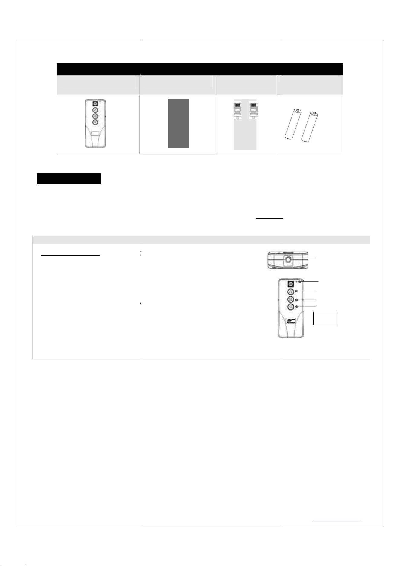
1. IR Remote control (
Item A, Fig 1
of sight contact using an effective
beam range of 25 feet within a 30
angle. Aim the IR remote directly at either the IR receiver on the Wall Box
Controller or on the screen to operate the screen.
Note: Assure there is no obstruction between the IR remote and IR
receiver.
Motorized Screen S
eries | Controls and
A. IR (Infra Red) Remote
Control ZRC1-IR
5
: Depending on your region, the screen will operate in either
110v or 220v voltage.
1. After ensuring the power outlet & screen are compatible (voltage), plug the power cord into the power
2. Once the screen has power, you’ll be able to control it using any of the
3
methods
Ways to control your Evanesce Tab
-Tension B screen
Item A, Fig 1
): The Infrared functions by direct line
beam range of 25 feet within a 30
-degree
angle. Aim the IR remote directly at either the IR receiver on the Wall Box
Controller or on the screen to operate the screen.
Note: Assure there is no obstruction between the IR remote and IR
eries | Controls and
Accessories
B. Wall box controller
ZRC1-WB
C. RJ50 Cable
ZRC1-RJ50
www.akiascreens.com
110v or 220v voltage.
1. After ensuring the power outlet & screen are compatible (voltage), plug the power cord into the power
methods
described below.
D. AAA batteries
LED light
UP
STOP
DOWN
Fig.1
IR remote
IR Lens
(IR remote only)
Rev. V11222023DT (DZUG0268) 6 www.akiascreens.com
2. Wall box controller (Item B, Fig 3): The wall box controller switch is a wall mounted control box with an
up/stop/down button. It plugs directly into the screen’s RJ50 port.
3.Wired 5-12 volt trigger: Requires a 3.5mm to 3.5mm mono cable (not included)
Step 1: Connect one end the RJ50 cable to the screen and the other end
to the Wall box controller.
Step 2: Then connect one end the 3.5mm mono cable to the wall box
controller and the other to the projector.
Once the two cables have been connected, the wired trigger feature
is ready to synchronize the screen’s up/down operation with the
projector’s power cycle.
Projector on, screen drops
Projector off, screen raises
ADVANCED Programming Key Instructions: (FOR ADVANCED USERS ONLY)
Wall box controller must be connected to the screen.
1. Preset the Screen’s Drop Position:
Use the RF/IR remote or Wall Box Controller to Drop the screen to the desired position you want to set it at.
ATTENTION: Reducing the factory’s full screen drop may produce waves/wrinkles on the projection
surface on tab-tension screens. The full drop is recommended to allow the screen to rely on the tab-
tension system to maintain the projection surface flat and taut on all sides.
The same applies on non-tensioned screens, although some level of waves may be present due to the
nature of the screen not being tensioned. If wrinkles/waves develop after making the adjustment to
the desired drop position, reset it to the factory’s default position per the instructions below.
FLATNESS AFFECTED BY NEW PROGRAMMED VERTICAL POSITION IS NOT COVERED UNDER A
REPLACEMENT WARRANTY.
3.5 mm port
DC 5-12V out
3.5mm to 3.5mm mono cable
Wall box controller
RJ50 cable
Fig. 4
Projector
Wall box controller
IR Receiver
RJ50 cable
Wall box controller
SIDE VIEW
RJ50 PORT:
Connects to the
Screen RJ50 PORT
(RJ50 CABLE ONLY)
3.5mm mono Projector
Trigger Port (if Projector
equipped)
Wall box controller
BACK VIEW
Programming
Key
Rev. V11222023DT (DZUG0268) 7 www.akiascreens.com
Press & hold the “Programming Key”, then press the “Down key” on the Wall Box Controller. The LED will flash 5
times to confirm new programmed drop position.
2. Clear/Reset the Screen’s Drop Position to factory default:
Press & hold the “Programming Key + “Stop key” on the wall box controller.
For more information, technical support or your local AKIA Screens contact,
please visit www.akiascreens.com
PROGAMMING NOTE:
The programmed vertical position relies on a time-count which adjusts itself according to the
programmed timed difference. Multiple up/down programming will result in the vertical position being
off a few inches. It is recommended that programming is done the first-time the desired vertical
position is determined or RESET it to factory default and programming the desired vertical position
afterwards.
Rev. V11222023DT (DZUG0268) 8 www.akiascreens.com
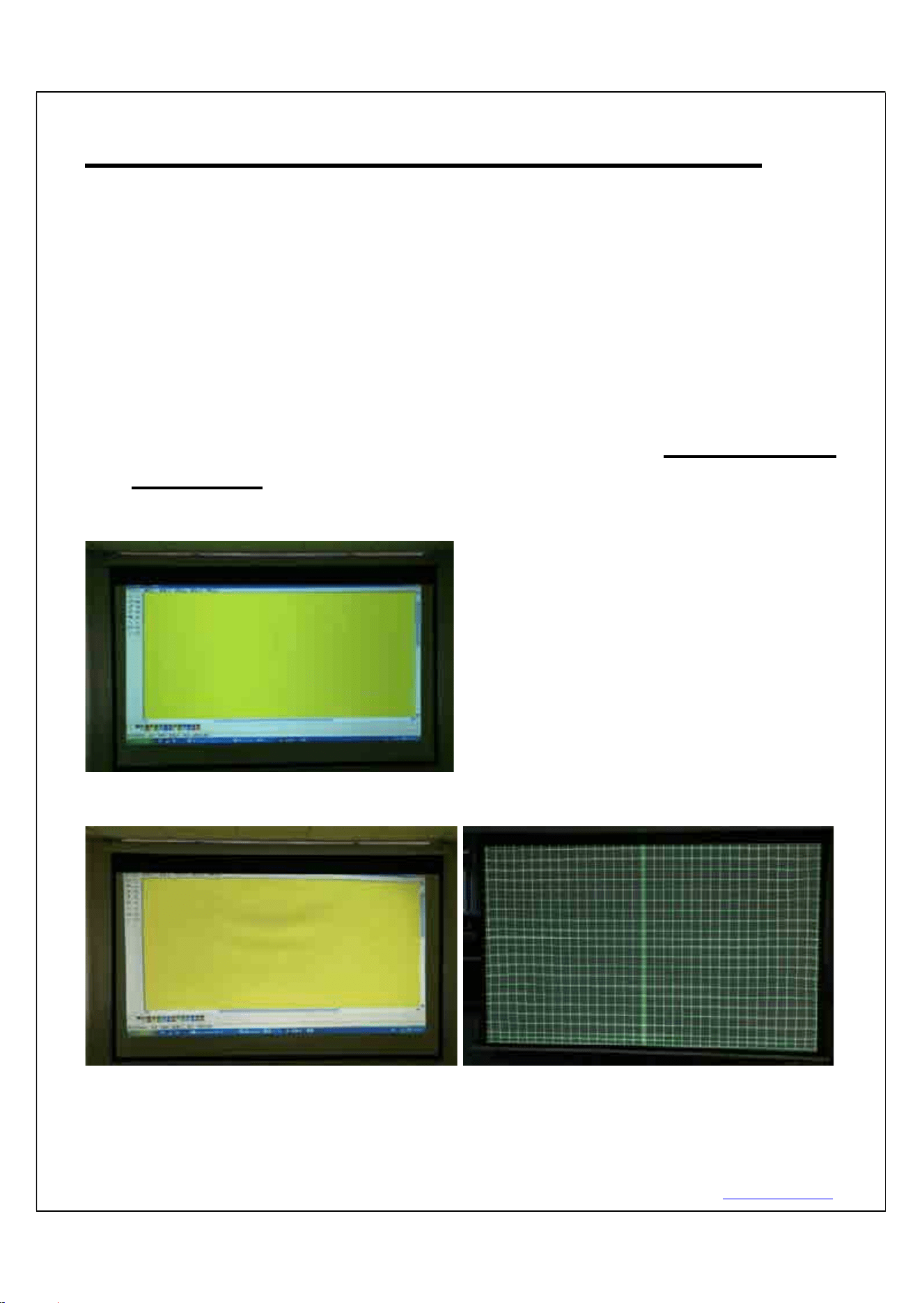
SHORT THROW PROJECTION DISCLAIMER
Using a short throw projector on a non-tensioned type screen will
result in image distortion as the slightest wave on the viewing
surface will become more evident.
For short throw projectors, AKIA Screens recommends the use of a
motorized tab-tensioned, fixed frame or whiteboard projection
screen.
Examples of undoctored projection images using a standard throw
and short-throw
projector
Standard throw projected image shown below (waves are not visible)
This short throw projected image shown below, demonstrates how waves on
the surface become more pronounced:
Actual Projection Images by two different AKIA Screens model with Standard Throw
Projector (Model #:ViewSonic Pro8300) vs. Short Throw Projector (Model
# :BenQW710ST)
Rev. V11222023DT (DZUG0268) 9 www.akiascreens.com
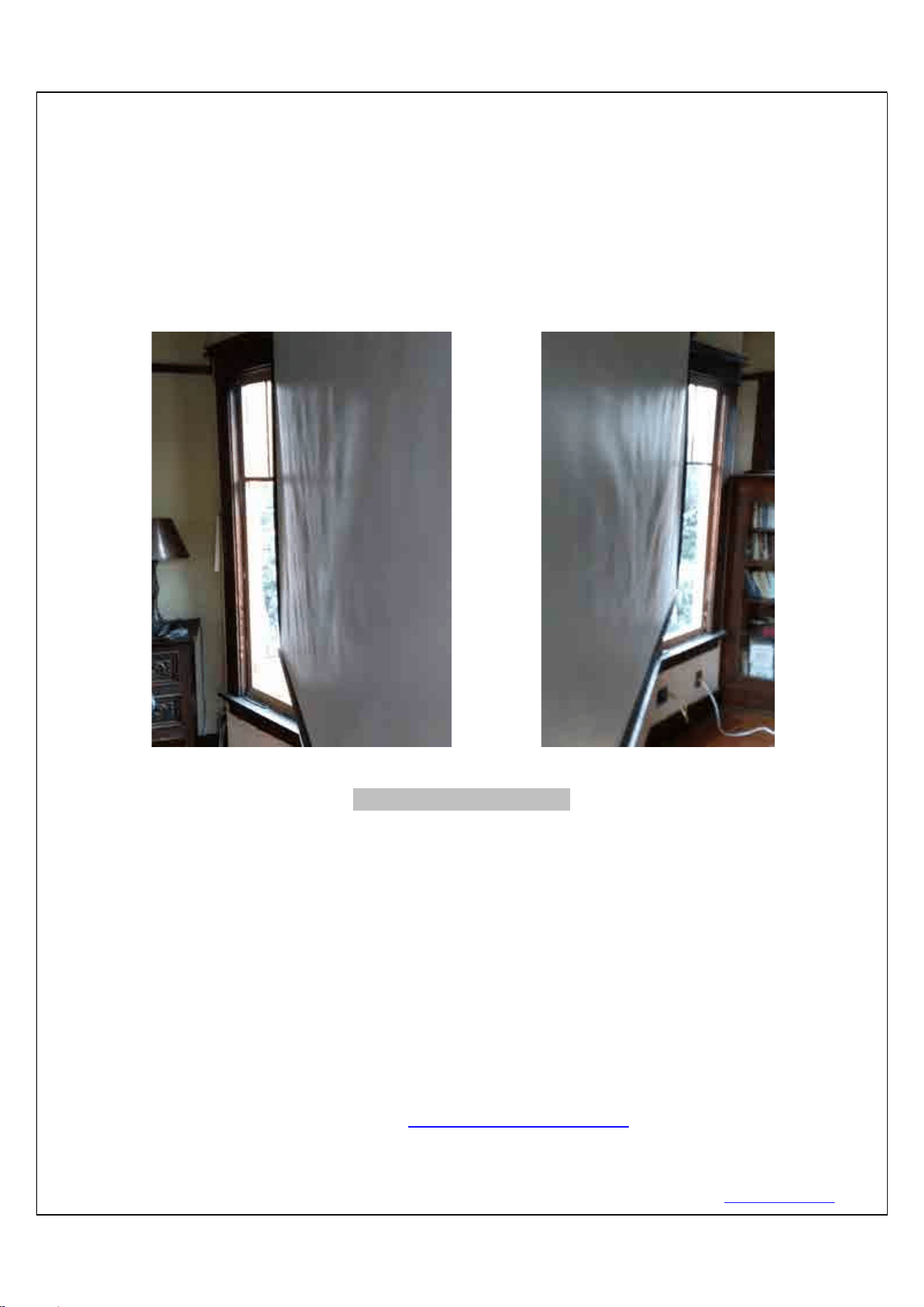
Direct Sunlight Disclaimer
Projection Screens from any maker are not designed for use as a window curtain and
should never be exposed to direct sunlight. Prolonged exposure to solar radiation will
destroy synthetic materials and such damage is not covered by our standard warranty.
See examples below.
SCREEN MATERIAL DISCLAIMER
At first, the screen material may have a series of noticeable horizontal lines on its surface. These are known as memory
lines. Memory lines are caused when the pliable projection material is rolled up and stored for the duration between its
production and sale. This is both a normal and correctable phenomenon. For non-tensioned screens, you may also notice
curling along the edges of the material. This is mainly due to environments in cold temperatures. Please try the following
to alleviate the memory lines and side curls on the material. After installation, leave the screen in the down position for a
few days in a warm room environment (above 75 degrees) and then commence regular (up/down) usage. This allows the
material to stretch out and cure itself. After a few days, the lines should vanish and the edge curling will alleviate and will
neither return nor affect the projected image during the years of its use.
For more information, technical support or your local AKIA Screens contact,
please visit www.akiascreens.com