Rev. 12172024BR www.akiascreens.com 1
Floor Motorized Tab-Tension CLR
®
3 Series
Floor Rising Ceiling/Ambient Light Rejecting (CLR
®
/ALR)
Tab-Tensioned Motorized Screen
User’s Guide – E/H Type (RC1)
V1.1
Visit www.akiascreens.com for latest updated version.
IMPORTANT SAFEGUARDS
Read these instructions carefully and retain them for future use. If this product is passed to a third
party, then these instructions must be included.
Caution:
The screen’s Black Bottom Rise is already set to its maximum rise distance. There is NO
extra Black Bottom Rise in the roller. Please be aware of this as it will void your warranty
with Akia Screens. Unapproved changes or modifications (except for cutting the power
cord for hardwire installations) to this unit are prohibited and will void your warranty.
• To avoid damaging the unit, do not use with any unauthorized accessories not recommended by
the supplier.
• Handle the unit carefully during transportation to avoid any damages.
• To ensure safe and reliable operation, direct connection to a properly grounded power source is
advised.
• The power outlet supplying power to the unit should be close to the unit and easily accessible.
• Do not install the unit on uneven or inclined surfaces.
• Do not put heavy objects on the power cord and position it properly to avoid creating a trip
obstacle.
• Never overload the power cord to prevent an electric shock or fire due to a loose contact or a
short circuit.
• There are not user serviceable parts in this unit. Do not attempt to disassemble this unit by
yourself. No one except authorized technicians can open and make repairs to this unit.
• Make sure the power source this unit is connected to has a continuous power flow.
• If there is need to use an extension cord, make sure the cord has an equal rating as the
appliance to avoid overheat.
• Do not handle the power plug when your hands are wet, or your feet are in contact with water.
Rev. 12172024BR www.akiascreens.com 2
Do not use this unit under the following circumstances.
• Disconnect the power cord under the conditions of heavy rain, wind, thunder, or lightning.
• Avoid direct Sunshine, rain shower and moisture.
• Keep away from fire sources and high temperature to prevent this device from overheating.
• Cut off the power supply first before transportation or maintenance.
• Fully disconnect from the power supply when the unit is not in use for a long period of time, as
should be done with any other electric household appliance.
• To avoid possible injury and/or an electric shock, do not attempt to use the screen if there is
obvious damage or if there are any evident broken parts.
• Keep hands clear from the closing panels.
• Keep away from children when screen is in operation.
WARNING
Individual modifications to this product are prohibited and will void the supplier’s warranty. Please contact
the Akia Screens
®
Customer Service Team with any questions.
SCREEN MAINTAINANCE
Dust, dirt, and scratches on the projection screen surface will affect the quality and performance of the
projection image. For optimal results we advise to pay attention to the following instructions.
1) The screen surface has a horizontal structure. DO NOT wipe the screen up and down or in a circular
motion.
Wipe very gently when needed from left to right only.
2) Please clean the dust on the screen surface with a soft brush or microfiber cloth (rough towel or
cloth may damage the screen’s surface).
3) Gently wipe the screen with a lightly moistened microfiber cloth with mild soap diluted in water.
Notes:
The following precautions should be followed at all times to avoid damaging the
material, which is not covered under warranty.
▪ Don’t touch the screen material to avoid leaving fingerprints. Use gloves when handling the
material.
▪ Don’t scratch the material, as it will leave permanent markings on the screen’s surface.
▪ Don’t point to the screen material with a fingertip or other sharp objects to prevent damage to
the material.
▪ Don’t use acetone, benzene, alcohol, and any other organic solvents to clean the screen
material. Using such chemicals will permanently damage the screen.
Rev. 12172024BR www.akiascreens.com 3
FCC Regulatory Compliance
This device complies with Part 15 of the FCC Rules.
Operation is subject to the following two conditions:
(1) this device may not cause harmful interference, and (2) this device must accept any interference received,
including interference that may cause undesired operation.
Changes or modifications not expressly approved by the party responsible for compliance could void the user’s
authority to operate the equipment.
This equipment has been tested and found to comply with the limits for a Class B digital device, pursuant to Part
15 of the FCC Rules. These limits are designed to provide reasonable protection against harmful interference in
a residential installation. This equipment generates, uses, and can radiate radio frequency energy and, if not
installed and used in accordance with the instructions, may cause harmful interference to radio communications.
However, there is no guarantee that interference will not occur in a particular installation.
If this equipment does cause harmful interference to radio or television reception, which can be determined by
turning the equipment off and on, the user is encouraged to try to correct the interference by one or more of the
following measures:
-- Reorient or relocate the receiving antenna.
-- Increase the separation between the equipment and receiver.
-- Connect the equipment into an outlet on a circuit different from that to which the receiver is connected.
-- Consult the dealer or an experienced radio/TV technician for help.
This equipment complies with FCC radiation exposure limits set forth for an uncontrolled environment. This
transmitter must not be co-located or operating in conjunction with any other antenna or transmitter.
Rev. 12172024BR www.akiascreens.com 4
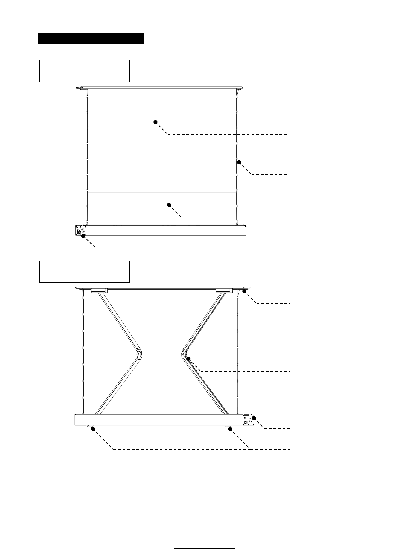
PARTS IDENTIFICATION
Note: Please always store the screen flat horizontally. Never store the screen in a vertical
position as it will permanently damage the screen’s structure, shift the material, and
cause wrinkles/folds which will void the warranty.
CLR
®
/CLR
®
3 Material
Bottom black masking
border
Power terminal /
Power switch
Tab/Strings
Cross-rising spring
scissor mechanism
Case/Housing
Closing Panel/Lid
Feet
Front of screen
Back of screen
Rev. 12172024BR www.akiascreens.com 5
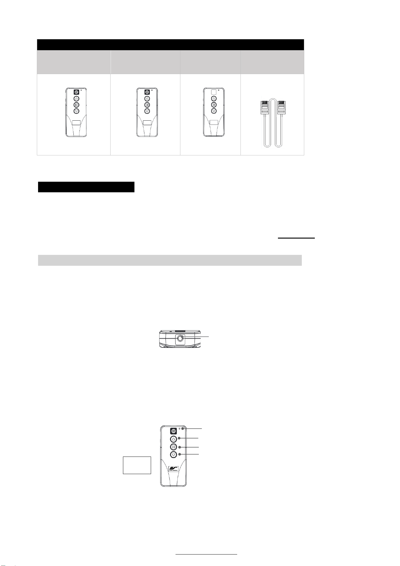
Floor Motorized Tension CLR 3 | Controls and Accessories
A. IR (InfraRed)
Remote Control
ZRC1-IR
B. RF (Radio
Frequency) Remote
control ZRC1-RF
C. Wall box
controller
ZRC1-WB
D. RJ50 Cable
ZRC1-RJ50
* Pre-installed
inside housing
SCREEN OPERATION
Electric Current: Depending on your region, the screen will operate in either 110v or 220v voltage.
1. After ensuring the power outlet & screen are compatible (voltage), plug the power cord into the power
outlet.
2. Once the screen has power, you’ll be able to control it using any of the 5 methods described below.
5 ways to control your Floor Motorized Tab-Tension Screen
1. IR Remote Control (Item A, Fig.1): The Infrared functions by direct line of sight contact using an
effective beam range of 25 feet within a 30-degree angle. Aim the IR remote directly at either the IR
receiver on the Wall Box Controller or on the screen to operate the screen.
Note: Assure there is no obstruction between the IR remote and IR receiver.
2. RF Remote Control (Item B, Fig.1): The radio waves eliminate the need for a direct line of sight
and has a longer distance control range.
The RF remote is already pre-synced/paired and ready to use. If synchronization/ pairing is
needed, please follow the steps below.
IR Lens
(IR remote only)
LED light
UP
STOP
DOWN
IR/RF remote
Fig.1
Rev. 12172024BR www.akiascreens.com 6
How to synchronize/pair a new RF remote:
• Press & hold the “Programming Key”, then press the “Up Key” on the Wall box controller (wall-
box LED flashes). Reference the wall box controller section for programming key location.
• Then press the “Up Key” on the RF remote.
The Wall box LED will flash 5 times, to indicate the RF remote has been properly
synchronized/paired.
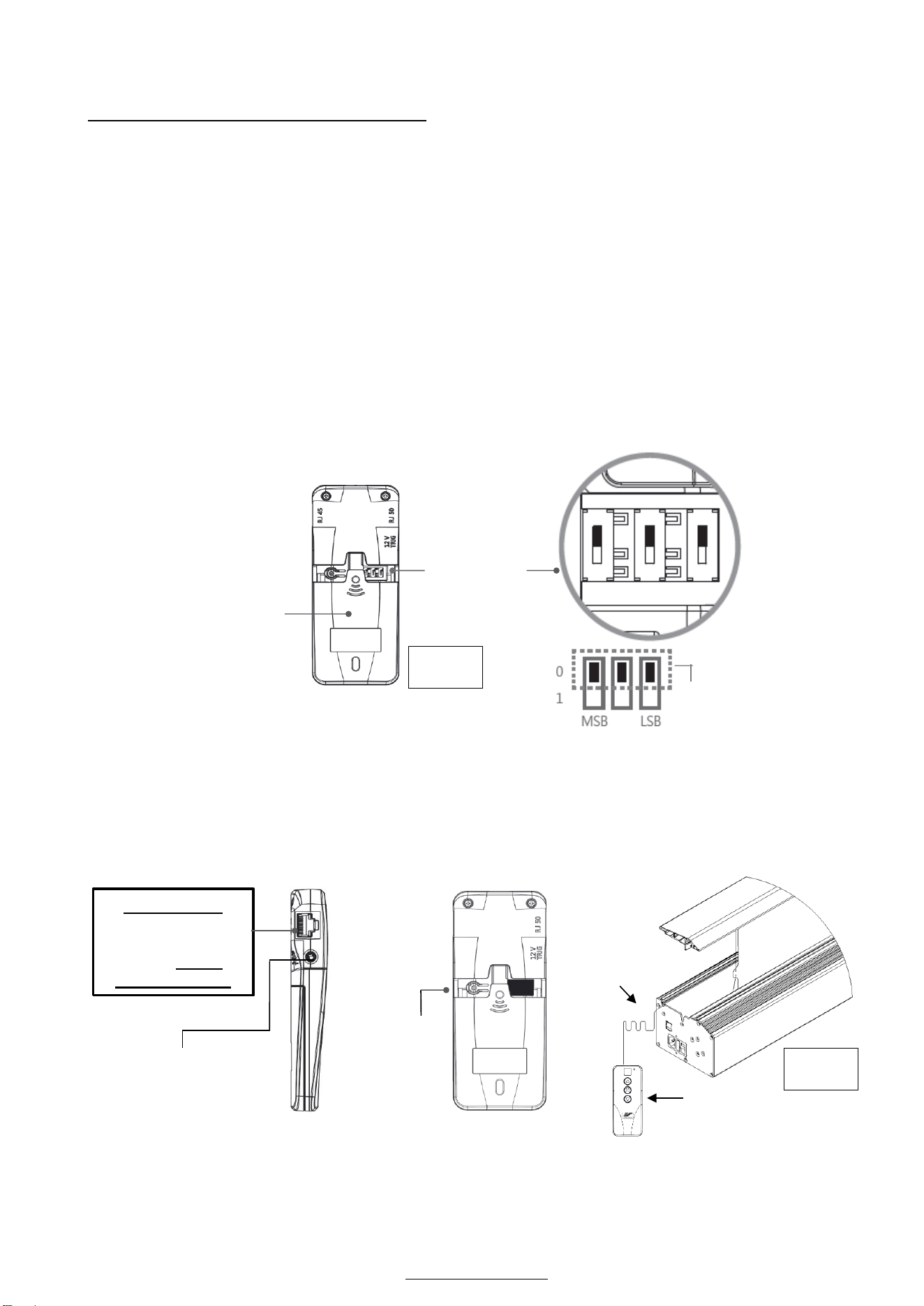
How to change the RF code (For use when multiple screens/RF remotes are owned, Fig.2)
Changing the RF code avoids controlling multiple screens at the same time and prevents electrical
interference leading to accidental control of the screen.
1. Remove the batteries
2. Change the RF code switch
3. Insert the batteries
4. Synchronize it with the wall box controller
3. Wall box controller (Item C, Fig.3): The wall box controller switch is a wall mounted control box
with an up/stop/down button. The RJ50 cable is pre-installed inside the housing. Plug the other
RJ50 end to the wall box controller. (Item D).
Battery
compartment
Default
“000”
RF Remote
BACK VIEW
Slide Switches
for RF Code
change
RJ50 cable
Wall box controller
SIDE VIEW
RJ50 PORT:
Connects to the
Screen RJ50
PORT (RJ50
CABLE ONLY)
3.5mm mono
Projector Trigger Port
(if Projector equipped)
Programming
Key
Wall box
Wall box controller
BACK VIEW
Fig.2
Fig.3
Rev. 12172024BR www.akiascreens.com 7
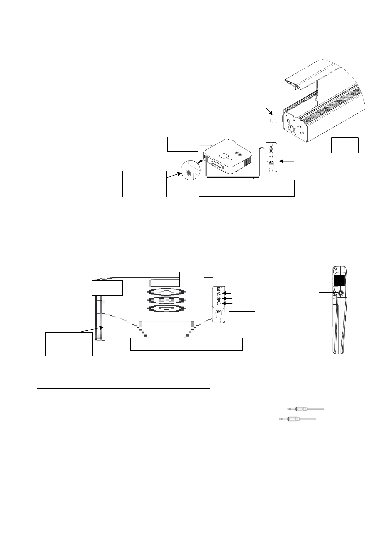
4. Wired 5-12 volt trigger (Fig.4): Requires a 3.5mm to 3.5mm mono cable (Not included)
Step 1: Connect the RJ50 cable that is pre-installed inside the
housing to the to the Wall box controller.
Step 2: Then connect one end the 3.5mm mono cable to the wall
box controller and the other to the projector.
Once the two cables have been connected, the wired trigger
feature is ready to synchronize the screen’s up/down operation
with the projector’s power cycle.
• Projector on, screen rises.
• Projector off, screen drops.
5. Wireless 5-12 volt trigger (Fig.5): Requires a 3.5mm to 3.5mm mono cable (Not included).
The Radio Frequency (RF) remote control serves as a dual purpose, independently as a handheld
remote control, or as a Wireless 5-12 volt trigger. The radio frequency technology sends a wireless
signal that synchronizes the screen’s drop & rise with the projector’s power cycle.
Here’s how to set up your Wireless 5-12 volt trigger
The 5-12V wireless trigger should already be synced and ready to work.
Step1: Connect one end of the 3.5 mm mono trigger cable to the RF remote.
Step 2: Connect the other 3.5 mm mono end of the cable to your projector
Step 3: Turn on the projector and the screen should automatically deploy.
Step 4: Turn off your projector and the screen should automatically retract.
(Please be aware, the projector on/off cycle may take longer to fully activate. It usually takes around 20-
30 seconds for full off and on cycle each time)
Note: If the wireless trigger feature does not work, please resync the RF remote to the Wall box
controller per the instructions in the Radio Frequency remote section.
Mono 3.5mm
Projector Trigger
Port
Fig 5
3.5 mm port
DC 5-12V out
3.5mm to 3.5mm mono cable
UP
STOP
DOWN
Projector
RF remote control
SIDE VIEW
3.5 mm port
DC 5-12V out
3.5mm to 3.5mm mono cable
Wall box
Fig. 4
Projector
RJ50 cable
Rev. 12172024BR www.akiascreens.com 8
ADVANCED Programming Key Instructions: (FOR ADVANCED USERS ONLY)
Wall box controller must be connected to the screen.
1. Preset the Screen’s Rise Position:
Use the RF/IR remote or Wall Box Controller to Raise the screen to the desired position you want to set it at.
Press & hold the “Programming Key”, then press the “UP key” on the Wall Box Controller. The LED will flash
5 times to confirm new programmed drop position.
2. Clear/Reset the Screen’s Drop Position to factory default:
Press & hold the “Programming Key + “Stop key” on the wall box controller.
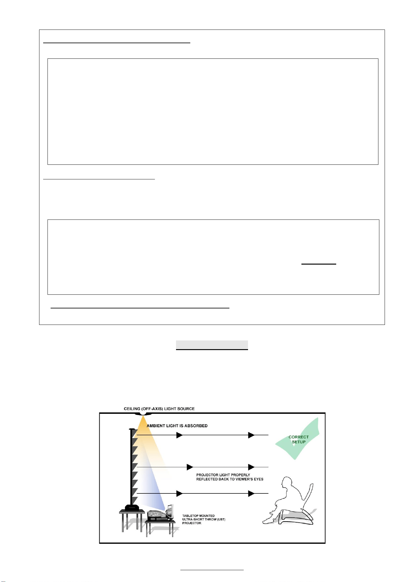
Notice to Installer:
PROPER PROJECTOR PLACEMENT
The CLR
®
/CLR
®
3 is exclusively for tabletop/bottom mounted ultra-short throw projectors.
See illustrations below for limits and criteria.
1) Tabletop mounted ultra-short throw projection illustration
PROGAMMING NOTE:
The programmed vertical position relies on a time-count which adjusts itself according to the
programmed timed difference. Multiple up/down programming will result in the vertical position
being off a few inches. It is recommended that programming is done the first-time the desired
vertical position is determined or RESET it to factory default and programming the desired vertical
position afterwards.
ATTENTION: Reducing the factory’s full screen rise may produce waves/wrinkles on the projection
surface on tab-tension screens. The full rise is recommended to allow the screen to rely on the tab-
tension system to maintain the projection surface flat and taut on all sides.
The same applies on non-tensioned screens, although some level of waves may be present due to the
nature of the screen not being tensioned. If wrinkles/waves develop after making the adjustment to
the desired rise position, reset it to the factory’s default position per the instructions below.
FLATNESS AFFECTED BY NEW PROGRAMMED VERTICAL POSITION IS NOT COVERED UNDER A
REPLACEMENT WARRANTY.
Rev. 12172024BR www.akiascreens.com 9
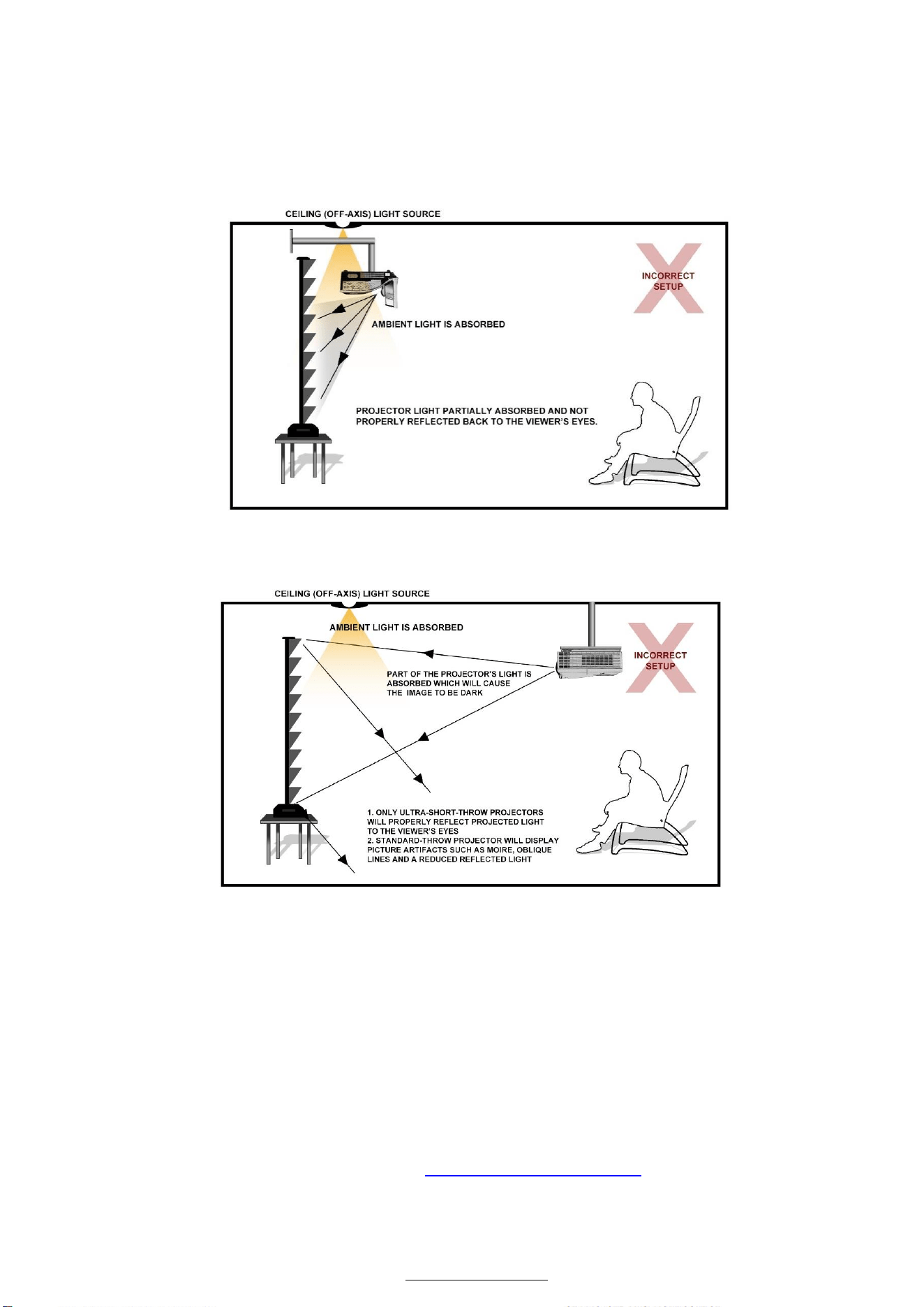
IMPROPER PROJECTOR PLACEMENT
Overhead placement or a standard throw projector will make the image very dark on account of the
screen’s absorbent layer deflecting light that is not aligned with its reflective angle.
1) Ceiling mounted Ultra-short throw projector illustration
2) Ceiling mounted Short and Standard throw Projector Illustration
Note: Images are not up to scale and are for illustrations purposes only
For more information, technical support or your local Akia Screens
®
contact,
please visit www.akiascreens.com