Rev. V04232024DT (DZUG0158) 1 www.akiascreens.com
Motorized Series
Electric Wall/Ceiling Projection Screen
User’s Guide – EN type
(RC1) V1.0
Important Safety & Warning Precautions
Make sure to read this user’s guide and follow the procedures below.
AKIA Screens allows a 1.5% tolerance within the viewing surface for expansion and contraction of the screen
materials over time.
Caution: The screen’s Black Top Drop is already set to its maximum drop distance. There is NO extra Black Top
Drop in the roller. Please be aware of this as it will void your warranty with AKIA Screens. Unapproved changes
or modifications (except for cutting the power cord for hardwire installations) to this unit are prohibited and will
void your warranty. For more information, please contact our Technical Support Department.
SCREEN MAINTAINANCE
Dust, dirt and scratches on the projection screen surface will affect the quality and performance of the
projection image. For optimal results we advise to pay attention to the following instructions.
1. Materials needed: Two Lint-Free white cloths, Mild Soap (hand soap is suitable) and Water.
2. Take the Lint-Free cloth and submerge it in warm water for cleaning light dust and dirt. For stubborn stains or
a sticky surface, a solution of hand soap diluted with warm water should be used.
3. Completely ring out cloth so it is lightly dampened, not drenched.
4. Using the damp cloth, lightly wipe in an up and down motion starting at the left of the screen moving to the
right of the screen. DO NOT WIPE IN CIRCULAR MOTION.
5. Once you have completed wiping the entire screen with a dampened Lint-Free cloth, use the dry Lint-Free cloth
to wipe off any excess water from the screen
Notes: The following precautions should be followed to avoid damaging the material, which is not
covered under warranty.
• Don’t scratch the material, as it will leave permanent markings on the screen’s surface.
• Don’t point to the screen material with a fingertip or other sharp objects to prevent damage to the material.
• Don’t use acetone, benzene, alcohol and any other organic solvents to clean the screen material. Using such
chemicals will permanently damage the screen.
Please retain this user’s guide for future reference.
• To avoid damaging the unit, do not use with any unauthorized accessories not recommended by the
manufacturer.
• Handle the unit carefully during transportation to avoid any damages.
• To ensure safe and reliable operation, direct connection to a properly grounded power source is advised.
• The power outlet supplying power to the unit should be close to the unit and easily accessible.
• Do not install the unit on uneven or inclined surfaces.
• Do not put heavy objects on the power cord and position it properly to avoid creating a trip obstacle.
Rev. V04232024DT (DZUG0158) 2 www.akiascreens.com
• Never overload the power cord to prevent an electric shock or fire due to a loose contact or a short circuit.
• There are not user serviceable parts in this unit. Do not attempt to disassemble this unit by yourself. No one
except authorized technicians can open and make repairs to this unit.
• Make sure the power source this unit is connected to has a continuous power flow.
• If there is need to use an extension cord, make sure the cord has an equal rating as the appliance to avoid
overheat.
• Do not handle the power plug when your hands are wet or your feet are in contact with water.
NOTE:
This equipment has been tested and found to comply with the limits for a Class B digital device, pursuant to Part
15 of the FCC Rules.
These limits are designed to provide reasonable protection against harmful interference in a residential
installation. This equipment generates and can radiate radio frequency energy and, if not installed and used in
accordance with the instructions, may cause harmful interference to radio communications.
However, there is no guarantee that the interference will not occur on a particular installation. If this equipment
causes harmful interference to radio or television reception, which can be determined by turning the equipment
off and on, the user is encouraged to try to correct the interference by one or more of the following measures.
✓ Reorient or relocate the receiving antenna of the device which may be causing the interference.
✓ Increase the separation between the screen and the device’s receiver.
✓ Connect the equipment into a different power outlet other than the device.
Pre-Installation
1. Carefully unpack the screen.
2. Always handle the screen in a leveled position on a clean surface.
3. In order to protect the screen from exposure to stains, keep the screen out of contact with foreign
particles such as dust, sawdust, and/or liquids.
SCREEN MATERIAL DISCLAIMER
At first, the screen material may have a series of noticeable horizontal lines on its surface. These are known as memory lines.
Memory lines are caused when the pliable projection material is rolled up and stored for the duration between its
production and sale. This is both a normal and correctable phenomenon. For non-tensioned screens, you may also notice
curling along the edges of the material. This is mainly due to environments in cold temperatures. Please try the following to
alleviate the memory lines and side curls on the material. After installation, leave the screen in the down position for a few
days in a warm room environment (above 75 degrees) and then commence regular (up/down) usage. This allows the
material to stretch out and cure itself. After a few days, the lines should vanish and the edge curling will alleviate and will
neither return nor affect the projected image during the years of its use.
Rev. V04232024DT (DZUG0158) 3 www.akiascreens.com
Please read this notice carefully before installation
Wall screws included with this product are complimentary and may not be adequate for all mounting
surfaces.
Consult with a professional installer or hardware store for proper mounting screws and anchors.
Regardless of the mounting method, the screen should be securely supported so that the vibration or pulling
on the viewing surface will not cause the screen case to become loose or fall. The installer must ensure that
the proper mounting hardware and the fasteners used are of adequate strength and suitable for the
mounting surface.
Installation Instructions
Note: Regardless of the mounting method, the screen should be securely supported so that the vibration or pulling
on the viewing surface will not cause the casing to become loose or fall.
Included are complimentary mounting screws that may or may not be appropriate for the installation you are
attempting. Always use the correct anchors to safely secure the screen.
1. Select the installation location for your screen. Ensure that it is within reasonable proximity from your
power source.
2. For best support of your screen, it is ideal to secure your screen into the studs of your house’s internal
framework. If studs are not available, use hollow anchors for mounting your wall screws into drywall. If
you’re installing in a concrete structure, use concrete bolts to secure your screen.
3. Ensure that both brackets are in perfect level alignment with one another. Use wall/ceiling wood screws to
secure to the wood studs. Use hollow anchors if mounting in drywall.
4. The screen casing is designed to accept the wall screws directly, be sure to position a washer between the
head of the wall-screw and the anchor slots on the screen’s casing.
5. Using a tape measure, mark the keyholes that are located at the back of the screen’s casing end cap.
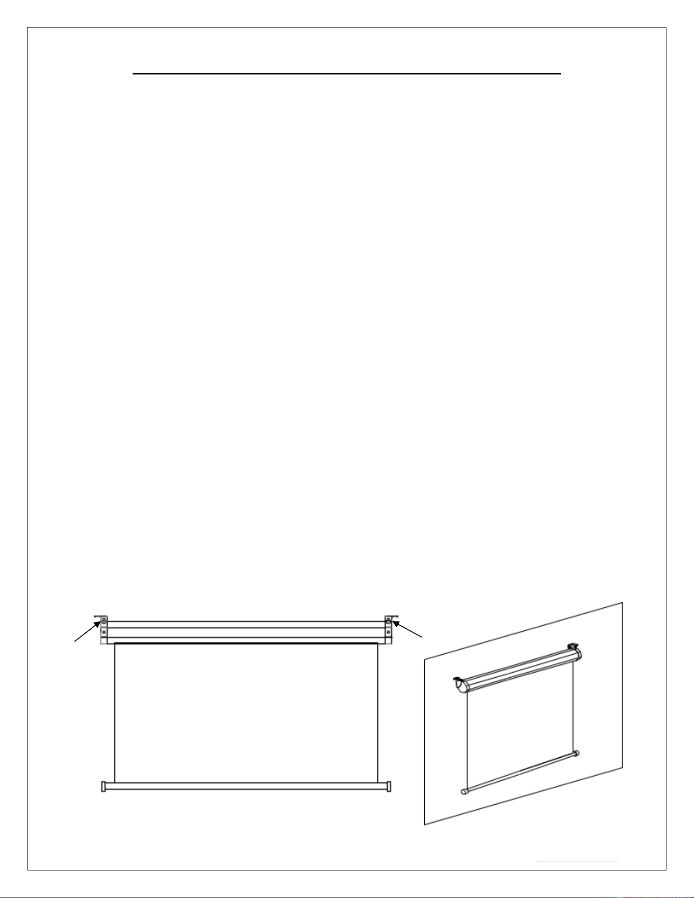
6. After marking the area and predrilled hole, insert the screw and have at least 1/8” from the wall/ceiling to
mount the screen. (See example in Figure 1.)
7. Figure 3 will show you an optional installation using chains (not included)
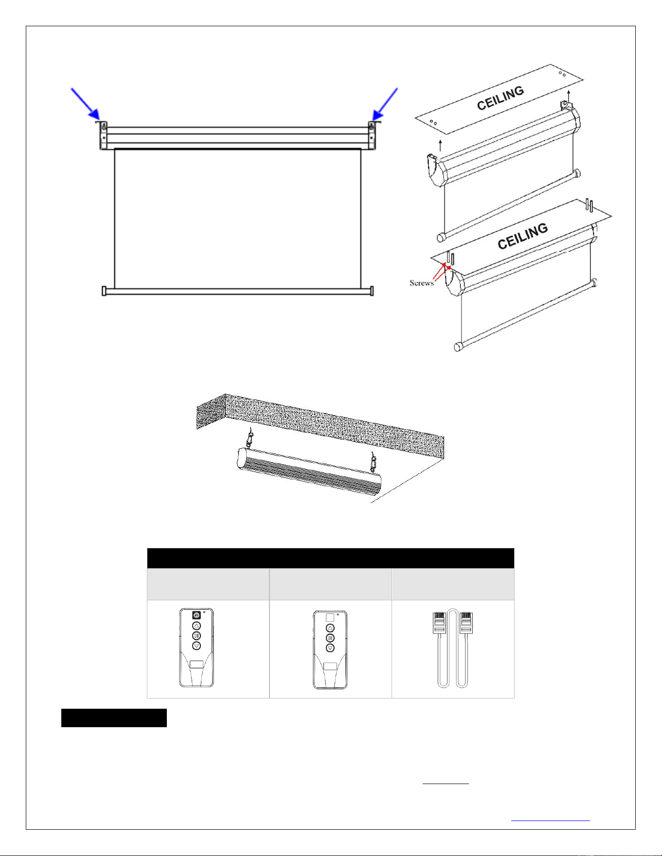
A. Flush wall installation using the back screw holes on the end cap brackets.
Fig. 1
Rev. V04232024DT (DZUG0158) 4 www.akiascreens.com
B. Flush ceiling installation using the top screw holes on the end cap brackets.
C. Optional installation method using a chain to hang the screen from the ceiling. (Chains not included)
Screen operation
Electric Current: Depending on your region, the screen will operate in either 110v or 220v voltage.
1. After ensuring the power outlet & screen are compatible (voltage), plug the power cord into the power
outlet.
2. Once the screen has power, you’ll be able to control it using any of the 3 methods described below.
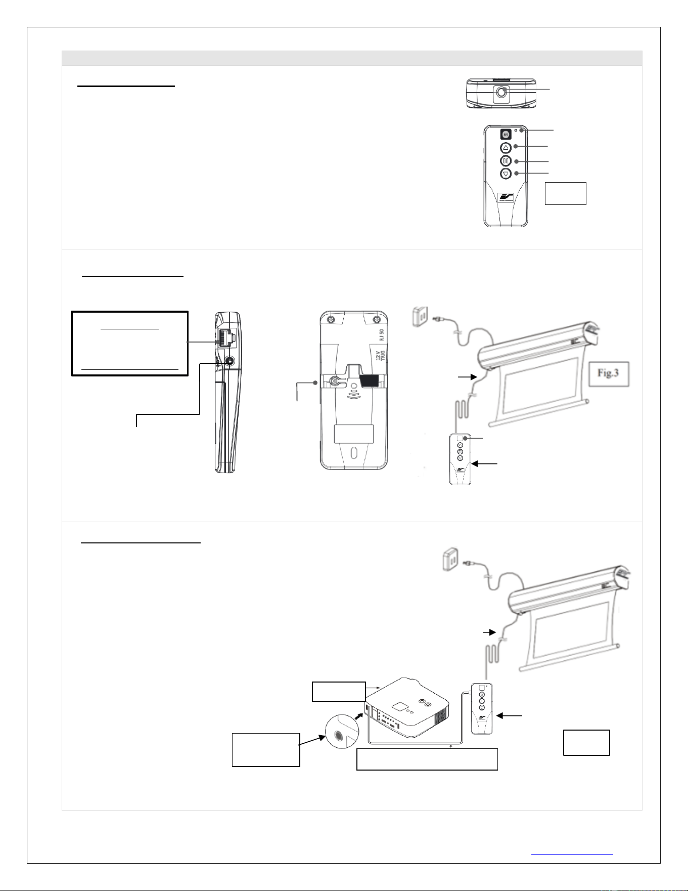
Motorized Screen Series | Controls and Accessories
A. IR (InfraRed) Remote
Controller ZRC1-IR
B. Wall box controller
ZRC1-WB
C. RJ50 Cable
ZRC1-RJ50
Fig. 2
Fig. 3
Rev. V04232024DT (DZUG0158) 5 www.akiascreens.com
3 Ways to control your Motorized Screen
1. IR Remote control (Item A, Fig 1): The Infrared functions by direct line of
sight contact using an effective beam range of 25 feet within a 30-degree angle.
Aim the IR remote directly at either the IR receiver on the Wall Box Controller
or on the screen to operate the screen.
Note: Assure there is no obstruction between the IR remote and IR receiver.
2. Wall box controller (Item B, Fig 3): The wall box controller switch is a wall mounted control box with an
up/stop/down button. It plugs directly into the screen’s RJ50 port.
3. Wired 5-12 volt trigger: Requires a 3.5mm to 3.5mm mono cable (not included)
Step 1: Connect one end the RJ50 cable to the screen and the other end
to the Wall box controller.
Step 2: Then connect one end the 3.5mm mono cable to the wall box
controller and the other to the projector.
Once the two cables have been connected, the wired trigger feature
is ready to synchronize the screen’s up/down operation with the
projector’s power cycle.
• Projector on, screen drops
• Projector off, screen raises
LED light
UP
STOP
DOWN
Fig.1
IR remote
IR Lens
(IR remote only)
3.5 mm port
DC 5-12V out
3.5mm to 3.5mm mono cable
Wall box controller
RJ50 cable
Fig. 4
Projector
Wall box controller
IR Receiver
RJ50 cable
Wall box controller
SIDE VIEW
RJ50 PORT:
Connects to the
Screen RJ50 PORT
(RJ50 CABLE ONLY)
3.5mm mono Projector
Trigger Port (if Projector
equipped)
Wall box controller
BACK VIEW
Programming
Key
Rev. V04232024DT (DZUG0158) 6 www.akiascreens.com
ADVANCED Programming Key Instructions: (FOR ADVANCED USERS ONLY)
Wall box controller must be connected to the screen.
1. Preset the Screen’s Drop Position:
Use the RF/IR remote or Wall Box Controller to Drop the screen to the desired position you want to set it at.
Press & hold the “Programming Key”, then press the “Down key” on the Wall Box Controller. The LED will flash 5
times to confirm new programmed drop position.
2. Clear/Reset the Screen’s Drop Position to factory default:
Press & hold the “Programming Key + “Stop key” on the wall box controller.
PROGAMMING NOTE:
The programmed vertical position relies on a time-count which adjusts itself according to the
programmed timed difference. Multiple up/down programming will result in the vertical position being
off a few inches. It is recommended that programming is done the first-time the desired vertical
position is determined or RESET it to factory default and programming the desired vertical position
afterwards.
ATTENTION: Reducing the factory’s full screen drop may produce waves/wrinkles on the projection
surface on tab-tension screens. The full drop is recommended to allow the screen to rely on the tab-
tension system to maintain the projection surface flat and taut on all sides.
The same applies on non-tensioned screens, although some level of waves may be present due to the
nature of the screen not being tensioned. If wrinkles/waves develop after making the adjustment to
the desired drop position, reset it to the factory’s default position per the instructions below.
FLATNESS AFFECTED BY NEW PROGRAMMED VERTICAL POSITION IS NOT COVERED UNDER A
REPLACEMENT WARRANTY.
Rev. V04232024DT (DZUG0158) 7 www.akiascreens.com
SHORT THROW PROJECTION DISCLAIMER
Using a short throw projector on a non-tensioned type screen will result in image
distortion as the slightest wave on the viewing surface will become more evident.
For short throw projectors, AKIA Screens recommends the use of a motorized tab-
tensioned, fixed frame or whiteboard projection screen.
Examples of undoctored projection images using a standard throw and short-throw
projector
Standard throw projected image shown below (waves are not visible)
This short throw projected image shown below, demonstrates how waves on
the surface become more pronounced:
Actual Projection Images by two different AKIA Screens model with Standard Throw
Projector (Model #:ViewSonic Pro8300) vs. Short Throw Projector (Model
# :BenQW710ST)
Rev. V04232024DT (DZUG0158) 8 www.akiascreens.com
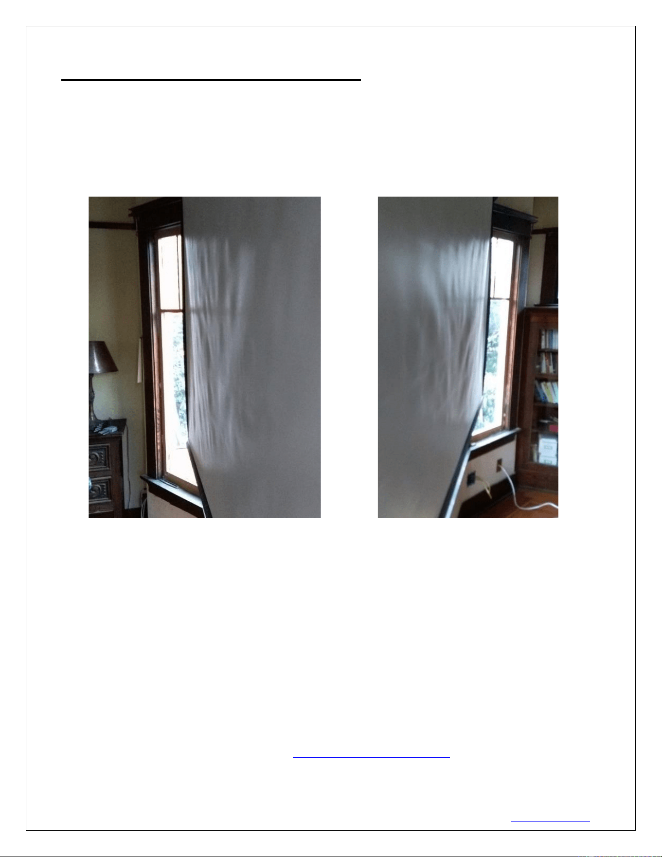
DIRECT SUNLIGHT DISCLAIMER
Projection Screens from any maker are not designed for use as a window curtain and
should never be exposed to direct sunlight. Prolonged exposure to solar radiation will
destroy synthetic materials and such damage is not covered by our standard warranty.
See examples below.
For more information, technical support or your local AKIA Screens contact,
please visit www.akiascreens.com