Rev.12172024BR
1
www.akiascreens.com
Electric Motorized Tab-Tension
CineGrey 4D AT Series
SWIFT-RC1™
Electric Wall/Ceiling Projection Screen
ALR/CLR Acoustically Transparent models
User’s Guide – H Type (RC1 V1.0)
Visit www.akiascreens.com for latest updated version.
Important Safety & Warning Precautions
Make sure to read this user’s guide and follow the procedures below.
Caution: The screen’s Black Top Drop is already set to its maximum drop limit. There is NO extra black drop material
in the roller. Please be aware that altering the vertical limit switch to drop the screen material off the roller voids
your warranty with Akia Screens. Unapproved changes or modifications (except for cutting the power cord for
hardwire installations) to this unit are prohibited and will void your warranty.
For more information, please contact our Technical Support Department at www.akiascreens.com
Akia Screens allows a 1.5% tolerance within the viewing surface for expansion and contraction of the screen
materials over time.
• Please retain this user’s guide for future reference.
• To avoid damaging the unit, do not use it with any unauthorized accessories not recommended by the
manufacturer.
• Handle the unit carefully during transportation to avoid any damages.
• To ensure safe and reliable operation, make sure the power connection is secure.
• The power source should be close to the unit and easily accessible.
• Do not install the unit on uneven, or inclined surfaces.
• To avoid electrical shock or product damage, do not install this device in a damp place.
• Do not place any heavy objects over the power cord.
• Position the power cord properly to avoid creating a trip hazard.
• Avoid electrical shock or fire, by not overloading the power cord.
• The internal & external parts of this unit are not end-user serviceable. Do not attempt to disassemble this unit
by yourself. Consult an authorized technician instead.
• Make sure the power source that this unit is connected to has a continuous power flow.
• If there is need to use an extension cord, make sure said cord has a compatible power rating.
• Do not handle this or any other electrical device if you are wet or standing in water.
• Whenever the screen reaches its end of life, follow local environmental guidelines regarding its proper
disposal.
Do not use this unit under the following circumstances.
• Disconnect the power cord if exposed to moisture, rain, wind, electrical storms, or snow.
• Avoid exposure to direct sunlight or any of the conditions stated in the previous bullet point.
• Keep away from fire or other high temperature heat sources.
• Cut off the power supply first before attempting maintenance or removal.
• Do not attempt to use this screen if there are obvious signs of damage.
• To avoid possible injury and/or an electric shock, do not attempt to use the screen if there is obvious damage
or if there are any evident broken parts.
Rev.12172024BR
2
www.akiascreens.com
WARNING
Due to various installation environments, the instructions provided in this user’s guide are for reference only.
Please consult a professional installation company for further installation and safety advice. The installer must
ensure that proper mounting hardware is used to provide adequate strength suitable for the installation.
Akia Screens is not liable for any faulty installations.
Individual modifications to this product are prohibited and will void the manufacturer’s warranty. Please contact
Akia Screens Customer Service Team with any questions.
NOTE: This equipment has been tested and found to comply with the limits for a Class B digital device, pursuant to
Part 15 of the FCC Rules. The product settings are designed to provide reasonable protection against any radio
interference within a residential installation. If properly installed, the screen may suffer from RF interference from
other home electronics.
Although radio interference affecting other household electronics is unlikely, the following steps can be taken
should RF interference occur.
✓ Reorient or relocate the receiving antenna on the device that may be casing the interference.
✓ Increase the distance between the screen and the interfering device’s receiver.
✓ Connect the projection screen to another power source apart from the interfering device.
Pre-Installation
1. Carefully unpack the screen.
2. Always handle the screen upright on a clean,
level surface.
3. Keep the screen out of contact with
foreign particles such as dust, sawdust,
and/or liquids.
4. Do not use this product in an outdoor
environment. Avoid areas with wind
blowing directly on the screen as this can
distort the projection image.
NOTE: Regardless of the mounting method, each screen should be securely installed so that vibrations or pulling on
the viewing surface will not cause the casing to become loose or fall. Included are complimentary mounting screws
that may or may not be appropriate for your installation. Always use the correct anchors to safely secure the screen
and always consult a professional integrator.
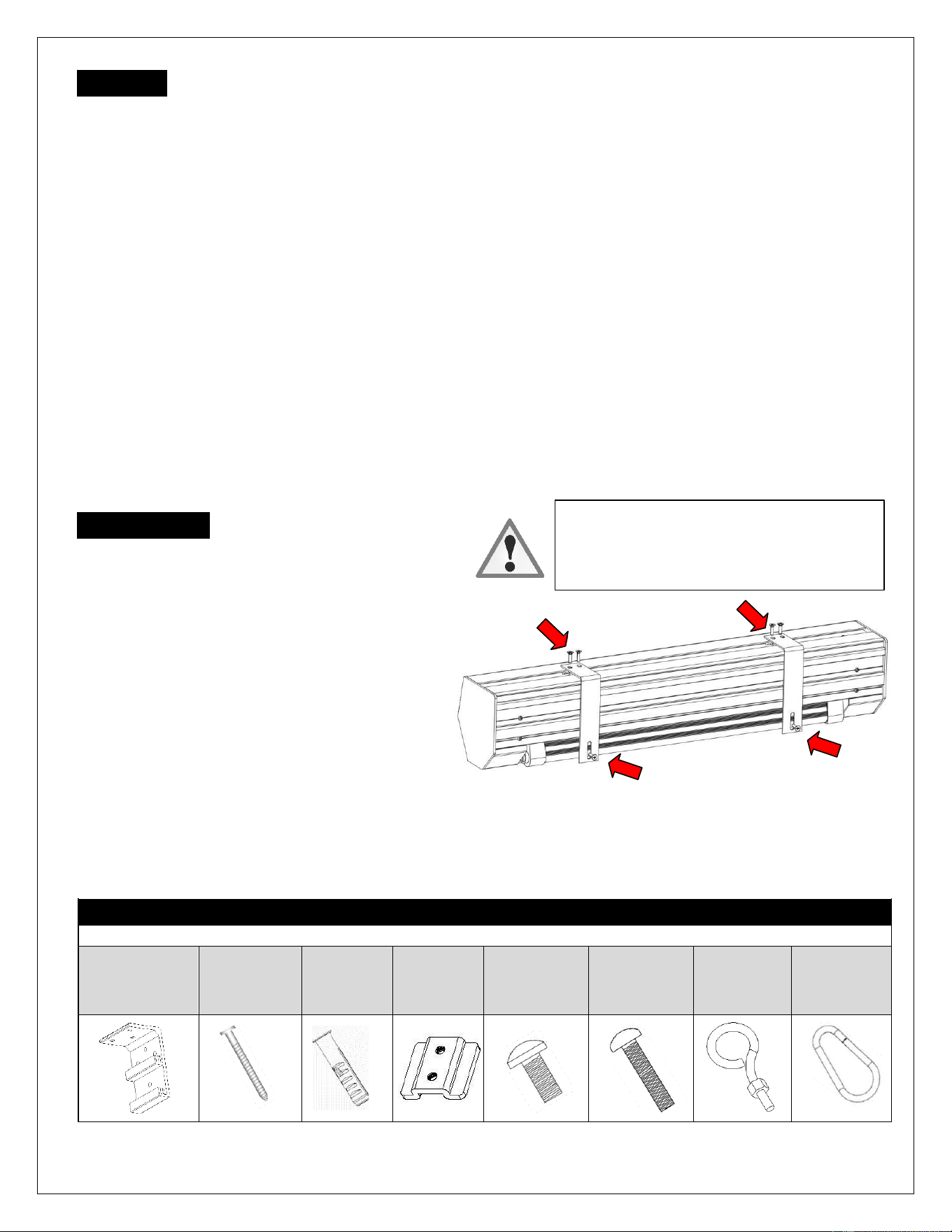
Hardware Parts List
Please make sure all parts listed below are included before proceeding with the installation.
A. Wall/Ceiling
mount bracket x2
B. M5x60mm
Screw x6
C. M12
Dry-wall
anchor x6
D. Bracket
connector x2
(Installed on
the housing)
E. M5x11mm
Bolt Screw x4
(Attached to
Part D)
F. M5x25mm
round head
cross screws x2
G. M5x30mm
eyebolt screw
& M5 nut x2
H. Carabiner x2
Please note:
Before fully operating the screen. Remove the
shipping brackets from the housing and the
weight bar by loosening the 6 screws.
Rev.12172024BR
3
www.akiascreens.com
Notice to Installer:
For CineGrey 4D AT models only
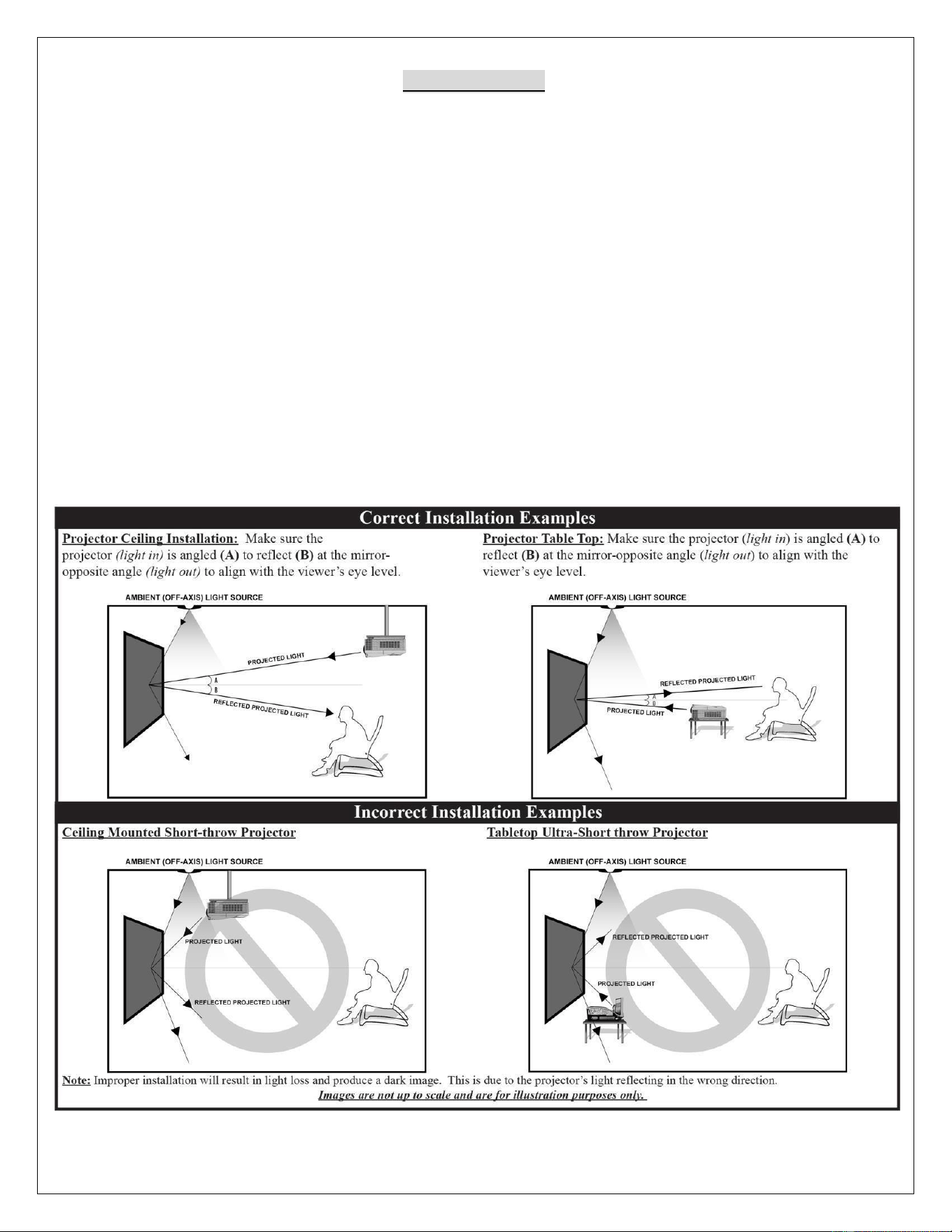
Please use the following installation instructions to obtain superior optical performance from the CineGrey 4D AT
Angular Reflective CLR /ALR (Ceiling Ambient Light Rejecting Acoustically Transparent) Screen.
Make sure to follow these instructions in order for the CineGrey 4D AT to perform correctly.
• Angular-Reflective material is not compatible with ultra/short-throw projectors
• Minimum lens throw ratio 1.5x image width
• Ambient light must not come from the same direction as the projector
Since angular-reflective means that the projected image will reflect at the mirror-opposite angle, it is important to
position the projector so that the viewer will get the best possible image.
Step 1: Establish the general “eye level” of the viewers.
Step 2: Set the appropriate projection level.
Rev.12172024BR
4
www.akiascreens.com
Installation Instructions
For installation assistance, please consult a professional Installer. Akia Screens is not liable for faulty installations.
Two or more people are required while one holds the screen in place.
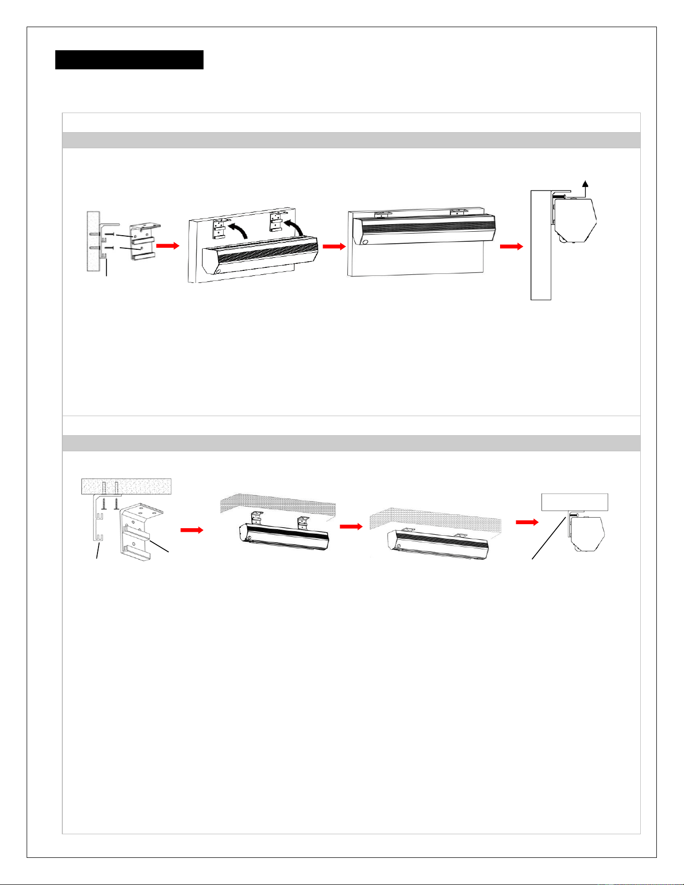
A. Wall Mount
Flush hidden mount (movable position)
This mount method allows the screen to slide horizontally.
M5x25MM round head cross screws (F)
Front view of bracket (A)
Wall
Side view of bracket (A)
1. Determine where the screen will be installed. Then, measure and mark the distance between the top and
bottom screw holes from each Wall/Ceiling mount bracket (A).
2. Drill a hole on all marked points and install the brackets with the dry-wall anchor(C), M5x60 screw (B), Make
sure both brackets are properly leveled.
3. Hang the screen by placing the lower “catch” located on the back over the brackets upper “catch”.
4. After making sure the screen is secured, you can slide it left / right to properly center it in position.
5. Lastly, screw the M5 screw (F) into the upper hole of the bracket to add additional support for the screen.
B. Ceiling Mount
I. Ceiling Mount (movable position)
This mount method allows the screen to slide horizontally.
Ceiling
Side view of Front view of M5x25MM round
bracket (A) bracket (A) head cross screws (F)
1. Determine where the screen will be installed. Then, measure and mark the distance between the top and
bottom screw holes from each Wall/Ceiling mount bracket (A).
2. Drill a hole on all marked areas and install the brackets with the dry-wall anchor(C), M5x60 screw (B), Make
sure both brackets are properly leveled.
3. Hang the screen by placing the lower “catch” located on the back over the bracket’s upper “catch”.
4. After making sure the screen is secured, you can slide it left / right to properly center it in position.
5. Lastly, screw the M5 screw (F) into the upper hole of the bracket to add additional support for the screen.
Rev.12172024BR
5
www.akiascreens.com
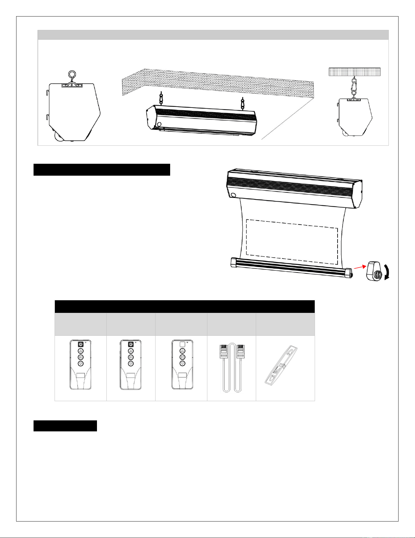
II. Suspended
1. Screw the eyebolt (G) onto the bracket connector (D).
2. Attach the carabiner (H) through the eyebolt (G) and connect it to the ceiling eyebolt screw (not included) as
rated for the screen’s weight.
Ceiling
Screen material tension adjustment
There is a material tension adjustment mechanism at side
cap of weight bar, turn clockwise and your screen will gain
more tension. Turn counterclockwise and the screen will
lose tension. Please note this adjustment is not necessary
as the tension of the screen has been pre- set to its factory
drop setting. If you would like to adjust the screen tension,
please contact Akia Screens
®
for assistance to avoid
damaging the screen and voiding your warranty.
Electric Tab-Tension CineGrey 4D AT | Controls and Accessories
A. IR Remote
ZRC1-IR
B. RF Remote
ZRC1-RF
C. Wall box
controller
ZRC1-WB
D. RJ50 Cable
ZRC1-RJ50
E. Bubble Level
Screen operation
Electric Current: 100 ~ 110v voltage
1. After ensuring the power outlet & screen are compatible (voltage), plug the power cord into the power outlet.
2. Once the screen has power, you’ll be able to control it using any of the 5 methods described below.
3. IR and RF remote controls require 2x AAA batteries (not included).
Push
Push
Rev.12172024BR
6
www.akiascreens.com
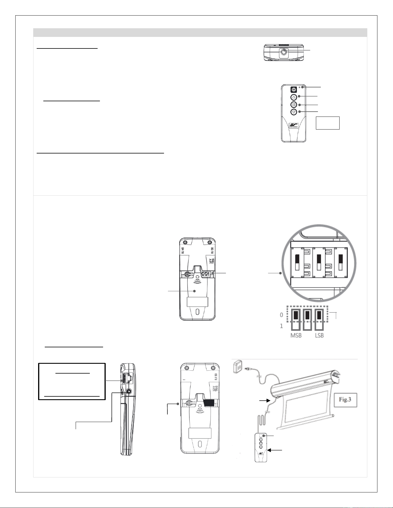
5 Ways to control your Electric Motorized Tab-Tension screen
1. IR Remote control (Item A, Fig 1): The Infrared functions by direct line of
sight contact using an effective beam range of 25 feet within a 30-degree angle.
Aim the IR remote directly at either the IR receiver on the Wall Box Controller
or on the screen to operate the screen.
Note: Assure there is no obstruction between the IR remote and IR receiver.
2. RF Remote Control (Item B): The radio waves eliminate the need for a direct
line of sight and has a longer distance control range.
The RF remote is already pre-synced/paired and ready to use. If
synchronization/ pairing is needed, please follow the steps below.
How to synchronize/pair a new RF remote:
• Press & hold the “Programming Key”, then press the “Up Key” on the Wall box controller (wall-box
LED flashes). Reference the wall box controller section for programming key location.
• Then press the “Up Key” on the RF remote.
• The Wall box LED will flash 5 times, to indicate the RF remote has been properly synchronized/paired.
How to change the RF code (For use when multiple screens/RF remotes are owned)
Changing the RF code avoids controlling multiple screens at the same time and prevents electrical interference
leading to accidental control of the screen.
1. Remove the batteries
2. Change the RF code switch
3. Insert the batteries
4. Synchronize it with the wall box controller
3. Wall box controller (Item C, Fig 3): The wall box controller switch is a wall mounted control box with an
up/stop/down button. It plugs directly into the screen’s RJ50 port.
LED light
UP
STOP
DOWN
Fig.1
IR/RF remote
IR Lens
(IR remote only)
Wall box controller
IR Receiver
RJ50 cable
Wall box controller
SIDE VIEW
RJ50 PORT:
Connects to the
Screen RJ50 PORT
(RJ50 CABLE ONLY)
3.5mm mono Projector
Trigger Port (if Projector
equipped)
Wall box controller
BACK VIEW
Programming
Key
Battery compartment
Default
“000”
RF Remote
BACK VIEW
Slide Switches
for RF Code
change
Rev.12172024BR
7
www.akiascreens.com
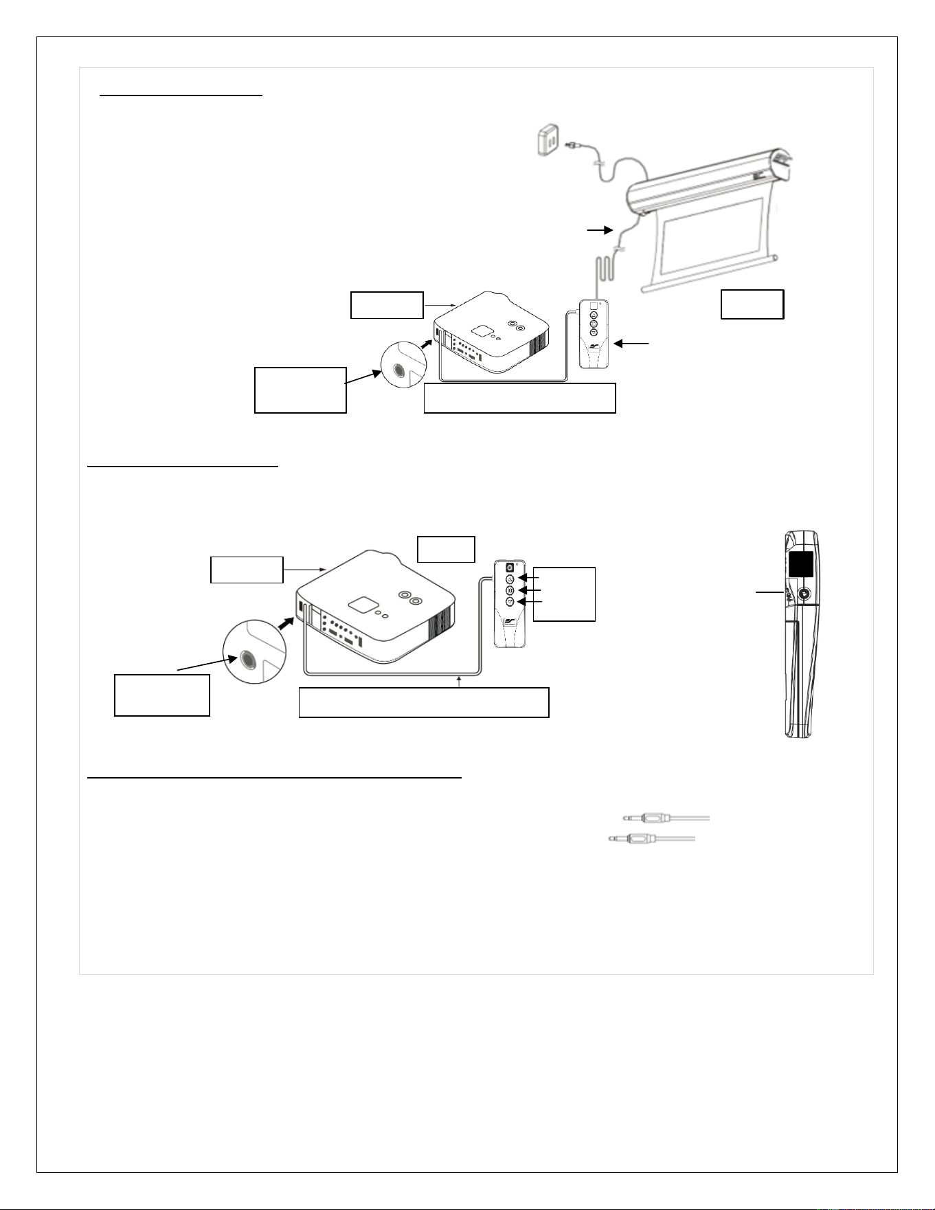
4.Wired 5-12 volt trigger: Requires a 3.5mm to 3.5mm mono cable (not included)
Step 1: Connect one end the RJ50 cable to the screen and the other end
to the Wall box controller.
Step 2: Then connect one end the 3.5mm mono cable to the wall
box controller and the other to the projector.
Once the two cables have been connected, the wired trigger
feature is ready to synchronize the screen’s up/down operation
with the projector’s power cycle.
• Projector on, screen drops
• Projector off, screen rises
5. Wireless 5-12 volt trigger (Fig 5): Requires a 3.5mm to 3.5mm mono cable (not included).
The Radio Frequency (RF) remote control serves as a dual purpose, independently as a handheld remote control, or
as a Wireless 5-12 volt trigger. The radio frequency technology sends a wireless signal that synchronizes the screen’s
drop & rise with the projector’s power cycle.
Here’s how to set up your Wireless 5-12 volt trigger
The 5-12V wireless trigger should already be synced and ready to work.
Step1: Connect one end of the 3.5 mm mono trigger cable to the RF remote.
Step 2: Connect the other 3.5 mm mono end of the cable to your projector
Step 3: Turn on the projector and the screen should automatically deploy.
Step 4: Turn off your projector and the screen should automatically retract.
(Please be aware, the projector on/off cycle may take longer to fully activate. It usually takes around 20-
30seconds for full off and on cycle each time)
Note: If the wireless trigger feature does not work, please resync the RF remote to the Wall box controller per the
instructions in the Radio Frequency remote section.
Fig 5
3.5 mm port
DC 5-12V out
3.5mm to 3.5mm mono cable
UP
STOP
DOWN
Projector
Mono 3.5mm
Projector Trigger
Port
RF remote control
SIDE VIEW
3.5 mm port
DC 5-12V out
3.5mm to 3.5mm mono cable
Wall box controller
Fig. 4
RJ50 cable
Projector
Rev.12172024BR
8
www.akiascreens.com
ADVANCED Programming Key Instructions: (FOR ADVANCED USERS ONLY)
* Wall box controller must be connected to the screen.
1.
Preset the Screen’s Drop Position:
Use the RF/IR remote or Wall Box Controller to Drop the screen to the desired position you want to set it at.
Press & hold the “Programming Key”, then press the “Down key” on the Wall Box Controller. The LED will flash 5
times to confirm new programmed drop position.
2.
Clear/Reset the Screen’s Drop Position to factory default:
Press & hold the “Programming Key + “Stop key” on the wall box controller.
For more information, technical support, or your local Akia Screens® contact,
please visit www.akiascreens.com
ATTENTION: Reducing the factory’s full screen drop may produce waves/wrinkles on the projection surface on
tab-tension screens. The full drop is recommended to allow the screen to rely on the tab- tension system to
maintain the projection surface flat and taut on all sides.
The same applies on non-tensioned screens, although some level of waves may be present due to the nature
of the screen not being tensioned. If wrinkles/waves develop after making the adjustment to the desired drop
position, reset it to the factory’s default position per the instructions below.
FLATNESS AFFECTED BY NEW PROGRAMMED VERTICAL POSITION IS NOT COVERED UNDER A REPLACEMENT
WARRANTY.
PROGAMMING NOTE:
The programmed vertical position relies on a time-count which adjusts itself according to the programmed
timed difference. Multiple up/down programming will result in the vertical position being off a few inches. It is
recommended that programming is done the first-time the desired vertical position is determined or RESET it
to factory default and programming the desired vertical position afterwards.