Loading ...
Loading ...
Loading ...

User Manual of Thermal Smart Linkage Tracking System
19
Figure 3-29 Junction Box Installation
3) Fix the junction box onto the PT joint with four M4×16 stainless steel screws.
CVBS
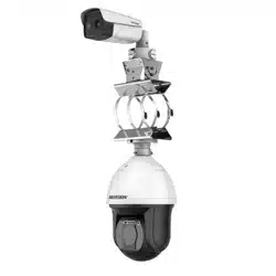
Figure 3-30 Bullet Camera Installation
8. Remove the protective film of the IR lens after you finish installing.
3.4 Angle Adjustment
Steps:
1. Loosen the screw to adjust the tilting position [0° to 90°]. Tighten the screw.
2. Loosen the screw to adjust the rotation position [0° to 360°]. Tighten the screw.
Screw
Loading ...
Loading ...
Loading ...