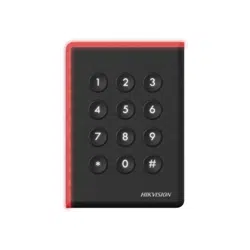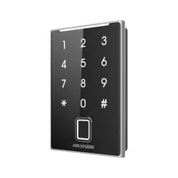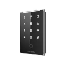

Card Reader
Quick Start Guide
UD30374B-B
2
Appearance
1 Installation
Figures are for reference only.
The device which supports card, touch key, QR code and
fingerprint is taken as an example for the figure of appearance.
The function of touch key/QR code or fingerprint can only be
supported by some types of devices. For figures of appearance
or more information of other types of devices, please refer to
the user manual.
Touch Key
LED
Indicator
Debugging Port (For
debugging only)
Power/RS-485/
Wiegand Interface
Tamper
Card/
Fingerprint
Presenting
Area
QR Code
Presenting Area
DIP Switch
Installation Environment:
Indoor and outdoor installation are supported. If
installing the device indoors, the device should be at
least 2 meters away from the light, and at least 3
meters away from the window or the door. If installing
the device outdoors, you should apply Silicone sealant
among the cable wiring area to keep the raindrop
from entering.
The additional force shall be equal to three times the
weight of the equipment. The equipment and its
associated mounting means shall remain secure
during the installation. After the installation, the
equipment, including any associated mounting plate,
shall not be damaged.
Direct
Sunlight
Direct Sunlight
through Window
Backlight
Indirect Sunlight
through Window
Close to Light
1
Make sure the gang box is installed on the wall.
2
Secure the mounting plate on the gang box with the two supplied
screws (SC-KA4X25).
Remove the back cover and route the cable
through the cable hole, wire the cables and insert the cables in the
gang box.
3
Align the device with the mounting plate, and secure the device on the
mounting plate with 2 supplied screw (SC-KM3X8T10-SUS-NL).
Wall Mounting with Gang Box
Gang box is not supplied.
Wall Mounting without Gang Box
1
Drill holes on the wall or other surface according to the instructions on the
mounting template.
2
Secure the mounting plate on the wall with two supplied screws (SC-KA4X25).
Remove the back cover and route the cable through the cable hole, wire the cables
and recover the back cover.
3
Align the device with the mounting plate, and secure the device on the
mounting plate with 1 supplied screw (SC-CM4X14_5T10-SUSS).
3
DIP Switch Description
DIP Switch Description
DIP switch 1~4 refers to RS-485
address. When the switch towards 1, it
refers to 1. When the switch is towards
0, it refers to 0.
DIP switch 6 refers to Wiegand protocol or RS-485 protocol. When the switch is
towards 1, it refers to Wiegand protocol. When the switch towards 0, it refers to
RS-485 protocol.
Represent 1 (ON) in binary mode
Represent 0 (OFF) in binary mode
The DIP switch module is shown as left. The No. of DIP switch
from left to right is 1 to 8.
DIP switch 5 refers to card security. When the switch is towards 1, it will enable
M1 card encryption function and disable door open via NFC card. When the
switch towards 0, it will disable M1 card encryption function, enable door open
via NFC card, and read card No.
DIP switch 7 refers to Wiegand Protocol (available when No. 6 is 1). When the
switch towards 1, it refers to Wiegand protocol of 26-bit. When the switch is
towards 0, it refers to Wiegand protocol of 34-bit.
DIP switch 8 refers to Matched Resistance (available for RS-485 protocol). When
the switch towards 1, it refers to Enable. When the switch is towards 0, it refers to
Disable.
RS-485
Address
DIP Switch
1
DIP Switch
2
DIP Switch
3
DIP Switch
4
Address 1 ON OFF OFF OFF
Address 2 OFF ON OFF OFF
Address 3 ON ON OFF OFF
Address 4 OFF OFF ON OFF
Scan the QR code to get the user manual for detailed
information.
5 Sound Prompt and Indicator
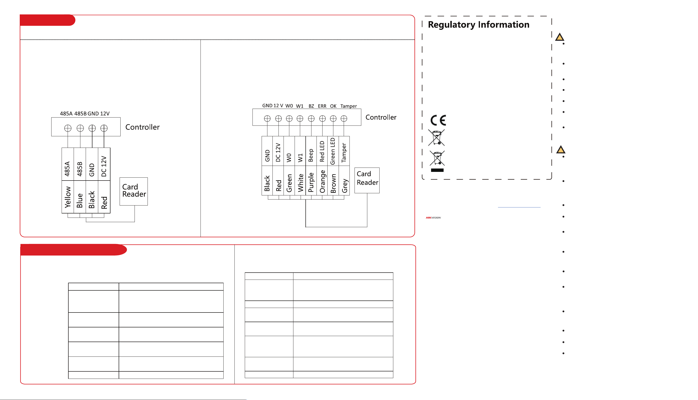
4 Wiring
Wiring for RS-485 Communication Mode Wiring for Wiegand Communication Mode
Steps
1. Set the DIP switch of No. 6 as 0.
2. Set the DIP switch of No. 1~4 for RS-485 address.
3. Wire the cable between controller and card reader as
shown below.
FCC Information
Please take attention that changes or modification not expressly approved by the party
responsible for compliance could void the user’s authority to operate the equipment. FCC
compliance: This equipment has been tested and found to comply with the limits for a Class
B digital device, pursuant to part 15 of the FCC Rules. These limits are designed to provide
reasonable protection against harmful interference in a residential installation. This
equipment generates, uses and can radiate radio frequency energy and, if not installed and
used in accordance with the instructions, may cause harmful interference to radio
communications. However, there is no guarantee that interference will not occur in a
particular installation. If this equipment does cause harmful interference to radio or
television reception, which can be determined by turning the equipment off and on, the user
is encouraged to try to correct the interference by one or more of the following measures:
—Reorient or relocate the receiving antenna.
—Increase the separation between the equipment and receiver.
—Connect the equipment into an outlet on a circuit different from that to which the receiver
is connected.
—Consult the dealer or an experienced radio/TV technician for help.
FCC Conditions
This device complies with part 15 of the FCC Rules. Operation is subject to the following two
conditions:
1. This device may not cause harmful interference.
2. This device must accept any interference received, including interference that may cause
undesired operation.
2006/66/EC (battery directive): This product contains a battery that cannot
be disposed of as unsorted municipal waste in the European Union. See the
product documentation for specific battery information. The battery is
marked with this symbol, which may include lettering to indicate cadmium
(Cd), lead (Pb), or mercury (Hg). For proper recycling, return the battery to
your supplier or to a designated collection point. For more information see:
www.recyclethis.info
2012/19/EU (WEEE directive): Products marked with this symbol cannot be
disposed of as unsorted municipal waste in the European Union. For proper
recycling, return this product to your local supplier upon the purchase of
equivalent new equipment, or dispose of it at designated collection points.
For more information see: www.recyclethis.info
This product and - if applicable - the supplied accessories too are marked
with "CE" and comply therefore with the applicable harmonized European
standards listed under the RE Directive 2014/53/EU, the EMC Directive
2014/30/EU, the RoHS Directive 2011/65/EU.
©2022 Hangzhou Hikvision Digital Technology Co., Ltd. All rights reserved.
About this Manual
The Manual includes instruc�ons for using and managing the Product. Pictures,
charts, images and all other informa�on hereina�er are for descrip�on and
explana�on only. The informa�on contained in the Manual is subject to change,
without no�ce, due to rmware updates or other reasons. Please nd the latest
version of this Manual at the Hikvision website (h�ps://www.hikvision.com/).
Please use this Manual with the guidance and assistance of professionals trained in
suppor�ng the Product.
Trademarks
and other Hikvision’s trademarks and logos are the proper�es of Hikvision
in various jurisdic�ons.
Other trademarks and logos men�oned are the proper�es of their respec�ve owners.
Disclaimer
TO THE MAXIMUM EXTENT PERMITTED BY APPLICABLE LAW, THIS MANUAL AND THE
PRODUCT DESCRIBED, WITH ITS HARDWARE, SOFTWARE AND FIRMWARE, ARE
PROVIDED “AS IS” AND “WITH ALL FAULTS AND ERRORS”. HIKVISION MAKES NO
WARRANTIES, EXPRESS OR IMPLIED, INCLUDING WITHOUT LIMITATION,
MERCHANTABILITY, SATISFACTORY QUALITY, OR FITNESS FOR A PARTICULAR
PURPOSE. THE USE OF THE PRODUCT BY YOU IS AT YOUR OWN RISK. IN NO EVENT
WILL HIKVISION BE LIABLE TO YOU FOR ANY SPECIAL, CONSEQUENTIAL, INCIDENTAL,
OR INDIRECT DAMAGES, INCLUDING, AMONG OTHERS, DAMAGES FOR LOSS OF
BUSINESS PROFITS, BUSINESS INTERRUPTION, OR LOSS OF DATA, CORRUPTION OF
SYSTEMS, OR LOSS OF DOCUMENTATION, WHETHER BASED ON BREACH OF
CONTRACT, TORT (INCLUDING NEGLIGENCE), PRODUCT LIABILITY, OR OTHERWISE, IN
CONNECTION WITH THE USE OF THE PRODUCT, EVEN IF HIKVISION HAS BEEN
ADVISED OF THE POSSIBILITY OF SUCH DAMAGES OR LOSS.
YOU ACKNOWLEDGE THAT THE NATURE OF THE INTERNET PROVIDES FOR INHERENT
SECURITY RISKS, AND HIKVISION SHALL NOT TAKE ANY RESPONSIBILITIES FOR
ABNORMAL OPERATION, PRIVACY LEAKAGE OR OTHER DAMAGES RESULTING FROM
CYBER-ATTACK, HACKER ATTACK, VIRUS INFECTION, OR OTHER INTERNET SECURITY
RISKS; HOWEVER, HIKVISION WILL PROVIDE TIMELY TECHNICAL SUPPORT IF
REQUIRED.
YOU AGREE TO USE THIS PRODUCT IN COMPLIANCE WITH ALL APPLICABLE LAWS,
AND YOU ARE SOLELY RESPONSIBLE FOR ENSURING THAT YOUR USE CONFORMS TO
THE APPLICABLE LAW. ESPECIALLY, YOU ARE RESPONSIBLE, FOR USING THIS PRODUCT
IN A MANNER THAT DOES NOT INFRINGE ON THE RIGHTS OF THIRD PARTIES,
INCLUDING WITHOUT LIMITATION, RIGHTS OF PUBLICITY, INTELLECTUAL PROPERTY
RIGHTS, OR DATA PROTECTION AND OTHER PRIVACY RIGHTS. YOU SHALL NOT USE
THIS PRODUCT FOR ANY PROHIBITED END-USES, INCLUDING THE DEVELOPMENT OR
PRODUCTION OF WEAPONS OF MASS DESTRUCTION, THE DEVELOPMENT OR
PRODUCTION OF CHEMICAL OR BIOLOGICAL WEAPONS, ANY ACTIVITIES IN THE
CONTEXT RELATED TO ANY NUCLEAR EXPLOSIVE OR UNSAFE NUCLEAR FUEL-CYCLE,
OR IN SUPPORT OF HUMAN RIGHTS ABUSES.
IN THE EVENT OF ANY CONFLICTS BETWEEN THIS MANUAL AND THE APPLICABLE
LAW, THE LATTER PREVAILS.
Data Protec�on
During the use of device, personal data will be collected, stored and processed. To
protect data, the development of Hikvision devices incorporates privacy by design
principles. For example, for device with facial recogni�on features, biometrics data is
stored in your device with encryp�on method; for ngerprint device, only ngerprint
template will be saved, which is impossible to reconstruct a ngerprint image.
As data controller, you are advised to collect, store, process and transfer data in
accordance with the applicable data protec�on laws and regula�ons, including
without limita�on, conduc�ng security controls to safeguard personal data, such as,
implemen�ng reasonable administra�ve and physical security controls, conduct
periodic reviews and assessments of the eec�veness of your security controls.
Wire the cables between controller and card reader, thus to establish the communication between them.
Steps
1. Set the DIP switch of No. 6 as 1.
2. Set the DIP switch of No. 5 and 7 for reading card mode
and Wiegand protocol.
3. Wire the cable between controller and card reader as
shown below.
Safety Instruction
!
!
Warning
All the electronic operation should be strictly compliance
with the electrical safety regulations, fire prevention
regulations and other related regulations in your local
region.
Please use the power adapter, which is provided by
normal company. The power consumption cannot be less
than the required value.
Do not connect several devices to one power adapter as
adapter overload may cause over-heat or fire hazard.
Please make sure that the power has been disconnected
before you wire, install or dismantle the device.
When the product is installed on wall or ceiling, the device
shall be firmly fixed.
If smoke, odors or noise rise from the device, turn off the
power at once and unplug the power cable, and then
please contact the service center.
If the product does not work properly, please contact your
dealer or the nearest service center. Never attempt to
disassemble the device yourself. (We shall not assume any
responsibility for problems caused by unauthorized repair
or maintenance.)
Caution
Do not drop the device or subject it to physical shock, and
do not expose it to high electromagnetism radiation. Avoid
the equipment installation on vibrations surface or places
subject to shock (ignorance can cause equipment
damage).
Do not place the device in extremely hot (refer to the
specification of the device for the detailed operating
temperature), cold, dusty or damp locations, and do not
expose it to high electromagnetic radiation. The
appropriate temperature is -40℃ to 65℃.
The device cover for indoor use shall be kept from rain and
moisture.
Exposing the equipment to direct sun light, low ventilation
or heat source such as heater or radiator is forbidden
(ignorance can cause fire danger).
Do not aim the device at the sun or extra bright places. A
blooming or smear may occur otherwise (which is not a
malfunction however), and affecting the endurance of
sensor at the same time.
Please use the provided glove when open up the device
cover, avoid direct contact with the device cover, because
the acidic sweat of the fingers may erode the surface
coating of the device cover.
Please use a soft and dry cloth when clean inside and
outside surfaces of the device cover, do not use alkaline
detergents.
Please keep all wrappers after unpack them for future use.
In case of any failure occurred, you need to return the
device to the factory with the original wrapper.
Transportation without the original wrapper may result in
damage on the device and lead to additional costs.
Improper use or replacement of the battery may result in
hazard of explosion. Replace with the same or equivalent
type only. Dispose of used batteries according to the
instructions provided by the battery manufacturer.
Please take care of your card and report card loss in time
when card is lost.
If you require a higher security level, use multiple
authentication modes.
Multiple card types are supported. Please select an
appropriate card type according to the card performance
and the usage scenarios.
After the card reader is powered on, LED status indicator will turn green and flashing
once. Then it will turn red and flashing 3 times. At last the buzzer will send out a beep
sound indicating the starting up process is completed.
Sound Prompt
Description
LED Indicator Description
Sound Prompt Description
One Beep
Successful operation of swiping card or
pressing keys; QR code is detected; Time
out prompt for pressing keys.
Two Beeps
The operation of swiping card is valid; The
door is opened.
Three Beeps
The operation of swiping card is invalid; Fail
to open the door.
Rapidly Continuous
Beeps
Prompt for tamper-proof alarm; Prompt for
buzzer alarm.
Slowly Continuous
Beeps
The card reader is unencrypted.
Eight Rapid Beeps The card is recognized as M1 card.
LED Indicator Status Description
Green (flashing
once), and red
(flashing 3 times)
The card reader is power on.
Flashing green Group recognition prompt.
Solid green for 2 s
The operation of pressing keys or swiping
card is valid.
Flashing red for 3
times
The operation of pressing keys or swiping
card is invalid.
Solid red
Standby mode under OSDP protocol. The
indicator is controlled by the access
controller.
Flashing red
For RS-485 protocol: Registering failed or
card reader is offline.
White Standby mode under RS-485 protocol.