
AA
Swing Barrier
Quick Start Guide

Swing Barrier • User Manual
1
Legal Information
© 2020 Hangzhou Hikvision Digital Technology Co., Ltd. All rights reserved.
This Manual is the property of Hangzhou Hikvision Digital Technology Co., Ltd. or its affiliates (hereinafter referred to
as "Hikvision"), and it cannot be reproduced, changed, translated, or distributed, partially or wholly, by any means,
without the prior written permission of Hikvision. Unless otherwise expressly stated herein, Hikvision does not make
any warranties, guarantees or representations, express or implied, regarding to the Manual, any information
contained herein.
About this Manual
The Manual includes instructions for using and managing the Product. Pictures, charts, images and all other
information hereinafter are for description and explanation only. The information contained in the Manual is subject
to change, without notice, due to firmware updates or other reasons. Please find the latest version of this Manual at
the Hikvision website (https://www.hikvision.com/).
Please use this Manual with the guidance and assistance of professionals trained in supporting the Product.
Trademarks Acknowledgement
and other Hikvision’s trademarks and logos are the properties of Hikvision in various jurisdictions.
Other trademarks and logos mentioned are the properties of their respective owners.
LEGAL DISCLAIMER
TO THE MAXIMUM EXTENT PERMITTED BY APPLICABLE LAW, THIS MANUAL AND THE PRODUCT DESCRIBED, WITH ITS
HARDWARE, SOFTWARE AND FIRMWARE, ARE PROVIDED “AS IS” AND “WITH ALL FAULTS AND ERRORS”. HIKVISION
MAKES NO WARRANTIES, EXPRESS OR IMPLIED, INCLUDING WITHOUT LIMITATION, MERCHANTABILITY,
SATISFACTORY QUALITY, OR FITNESS FOR A PARTICULAR PURPOSE. THE USE OF THE PRODUCT BY YOU IS AT YOUR
OWN RISK. IN NO EVENT WILL HIKVISION BE LIABLE TO YOU FOR ANY SPECIAL, CONSEQUENTIAL, INCIDENTAL, OR
INDIRECT DAMAGES, INCLUDING, AMONG OTHERS, DAMAGES FOR LOSS OF BUSINESS PROFITS, BUSINESS
INTERRUPTION, OR LOSS OF DATA, CORRUPTION OF SYSTEMS, OR LOSS OF DOCUMENTATION, WHETHER BASED ON
BREACH OF CONTRACT, TORT (INCLUDING NEGLIGENCE), PRODUCT LIABILITY, OR OTHERWISE, IN CONNECTION WITH
THE USE OF THE PRODUCT, EVEN IF HIKVISION HAS BEEN ADVISED OF THE POSSIBILITY OF SUCH DAMAGES OR LOSS.
YOU ACKNOWLEDGE THAT THE NATURE OF INTERNET PROVIDES FOR INHERENT SECURITY RISKS, AND HIKVISION
SHALL NOT TAKE ANY RESPONSIBILITIES FOR ABNORMAL OPERATION, PRIVACY LEAKAGE OR OTHER DAMAGES
RESULTING FROM CYBER-ATTACK, HACKER ATTACK, VIRUS INSPECTION, OR OTHER INTERNET SECURITY RISKS;
HOWEVER, HIKVISION WILL PROVIDE TIMELY TECHNICAL SUPPORT IF REQUIRED.
YOU AGREE TO USE THIS PRODUCT IN COMPLIANCE WITH ALL APPLICABLE LAWS, AND YOU ARE SOLELY RESPONSIBLE
FOR ENSURING THAT YOUR USE CONFORMS TO THE APPLICABLE LAW. ESPECIALLY, YOU ARE RESPONSIBLE, FOR
USING THIS PRODUCT IN A MANNER THAT DOES NOT INFRINGE ON THE RIGHTS OF THIRD PARTIES, INCLUDING
WITHOUT LIMITATION, RIGHTS OF PUBLICITY, INTELLECTUAL PROPERTY RIGHTS, OR DATA PROTECTION AND OTHER
PRIVACY RIGHTS. YOU SHALL NOT USE THIS PRODUCT FOR ANY PROHIBITED END-USES, INCLUDING THE
DEVELOPMENT OR PRODUCTION OF WEAPONS OF MASS DESTRUCTION, THE DEVELOPMENT OR PRODUCTION OF
CHEMICAL OR BIOLOGICAL WEAPONS, ANY ACTIVITIES IN THE CONTEXT RELATED TO ANY NUCLEAR EXPLOSIVE OR .

Swing Barrier • User Manual
2
Data Protection
During the use of device, personal data will be collected, stored and processed. To protect data, the
development of Hikvision devices incorporates privacy by design principles. For example, for device with facial
recognition features, biometrics data is stored in your device with encryption method; for fingerprint device,
only fingerprint template will be saved, which is impossible to reconstruct a fingerprint image.
As data controller, you are advised to collect, store, process and transfer data in accordance with the
applicable data protection laws and regulations, including without limitation, conducting security controls to
safeguard personal data, such as, implementing reasonable administrative and physical security controls,
conduct periodic reviews and assessments of the effectiveness of your security controls.

Swing Barrier • User Manual
3
FCC Information
Please take attention that changes or modification not expressly approved by the party responsible for compliance
could void the user’s authority to operate the equipment.
FCC compliance: This equipment has been tested and found to comply with the limits for a Class A digital device,
pursuant to part 15 of the FCC Rules. These limits are designed to provide reasonable protection against harmful
interference when the equipment is operated in a commercial environment. This equipment generates, uses, and can
radiate radio frequency energy and, if not installed and used in accordance with the instruction manual, may cause
harmful interference to radio communications. Operation of this equipment in a residential area is likely to cause
harmful interference in which case the user will be required to correct the interference at his own expense.
FCC Conditions
This device complies with part 15 of the FCC Rules. Operation is subject to the following two conditions:
1. This device may not cause harmful interference.
2. This device must accept any interference received, including interference that may cause undesired operation.
EU Conformity Statement
This product and - if applicable - the supplied accessories too are marked with "CE" and comply therefore
with the applicable harmonized European standards listed under the EMC Directive 2014/30/EU, the LVD
Directive 2014/35/EU, the RoHS Directive 2011/65/EU.
2012/19/EU (WEEE directive): Products marked with this symbol cannot be disposed of as unsorted
municipal waste in the European Union. For proper recycling, return this product to your local supplier
upon the purchase of equivalent new equipment, or dispose of it at designated collection points. For more
information see: www.recyclethis.info
2006/66/EC (battery directive): This product contains a battery that cannot be disposed of as unsorted
municipal waste in the European Union. See the product documentation for specific battery information.
The battery is marked with this symbol, which may include lettering to indicate cadmium (Cd), lead (Pb), or
mercury (Hg). For proper recycling, return the battery to your supplier or to a designated collection point. For more
information see: www.recyclethis.info
Industry Canada ICES-003 Compliance
This device meets the CAN ICES-3 (A)/NMB-3(A) standards requirements.
Swing Barrier • User Manual
4
Applicable Models
This manual is applicable to the models listed in the following table.
Series
Model
DS-K3BC411X
DS-K3BC411X-L
DS-K3BC411X-R
Symbol Conventions
The symbols that may be found in this document are defined as follows.
Safety Instructions
Proper configuration of all passwords and other security settings is the responsibility of the
installer and/or end-user.
In the use of the product, you must be in strict compliance with the electrical safety
regulations of the nation and region. Please refer to technical specifications for detailed
information.
Input voltage should meet both the SELV (Safety Extra Low Voltage) and the Limited Power
Source with 100 to 240 VAC or 12 VDC according to the IEC60950-1 standard. Please refer to
technical specifications for detailed information.
Do not connect several devices to one power adapter as adapter overload may cause
over-heating or a fire hazard.
Please make sure that the plug is firmly connected to the power socket.
If smoke, odor or noise rise from the device, turn off the power at once and unplug the power
cable, and then please contact the service center.
Symbol
Description
Provides additional information to emphasize or supplement
important points of the main text.
Indicates a potentially hazardous situation, which if not avoided,
could result in equipment damage, data loss, performance
degradation, or unexpected results.
Indicates a hazard with a high level of risk, which if not avoided, will
result in death or serious injury.

Swing Barrier • User Manual
5
CONTENTS
1 Product introduction ........................................................................ 6
1.1 Brief introduction ........................................................................... 6
1.2 Product structure and principle ...................................................... 6
1.3 Function Features ........................................................................... 9
1.4 Technical parameters ...................................................................... 9
2 Equipment Installation...................................................................... 9
2.1 Installation notes ............................................................................ 9
2.2 Equipment Installation.................................................................... 9
2.3 Connection .................................................................................... 12
2.4 Debugging instruction .................................................................. 12
2.5 Use notes ...................................................................................... 13
3 Control Board and parameter instruction ........................................ 13
3.1 Control Board instruction ............................................................. 13
3.2 Wiring diagram ............................................................................. 16
3.3 parameter instruction ................................................................... 18
4 Trouble shooting and maintenance ................................................. 20
4.1 Trouble shooting ........................................................................... 21
4.2 maintenance ................................................................................. 22
Swing Barrier • User Manual
6
1 Product introduction
1.1 Brief introduction
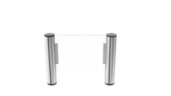
The flap /slide barrier and swing gate is a kind of 2-way speed access control equipment
designed for places with high class security requirements. It is easy to combine IC access control,
ID access control, code reader, fingerprint, face recognition and other identification devices,It
realizes the intelligent and efficient management of passage.
1.2 Product structure and principle
The structure of the product is mainly composed of mechanical system and electric control
system.
The mechanical system is composed of cabinet and core mechanism. The cabinet is equipped
with indicator, infrared sensor and other device.
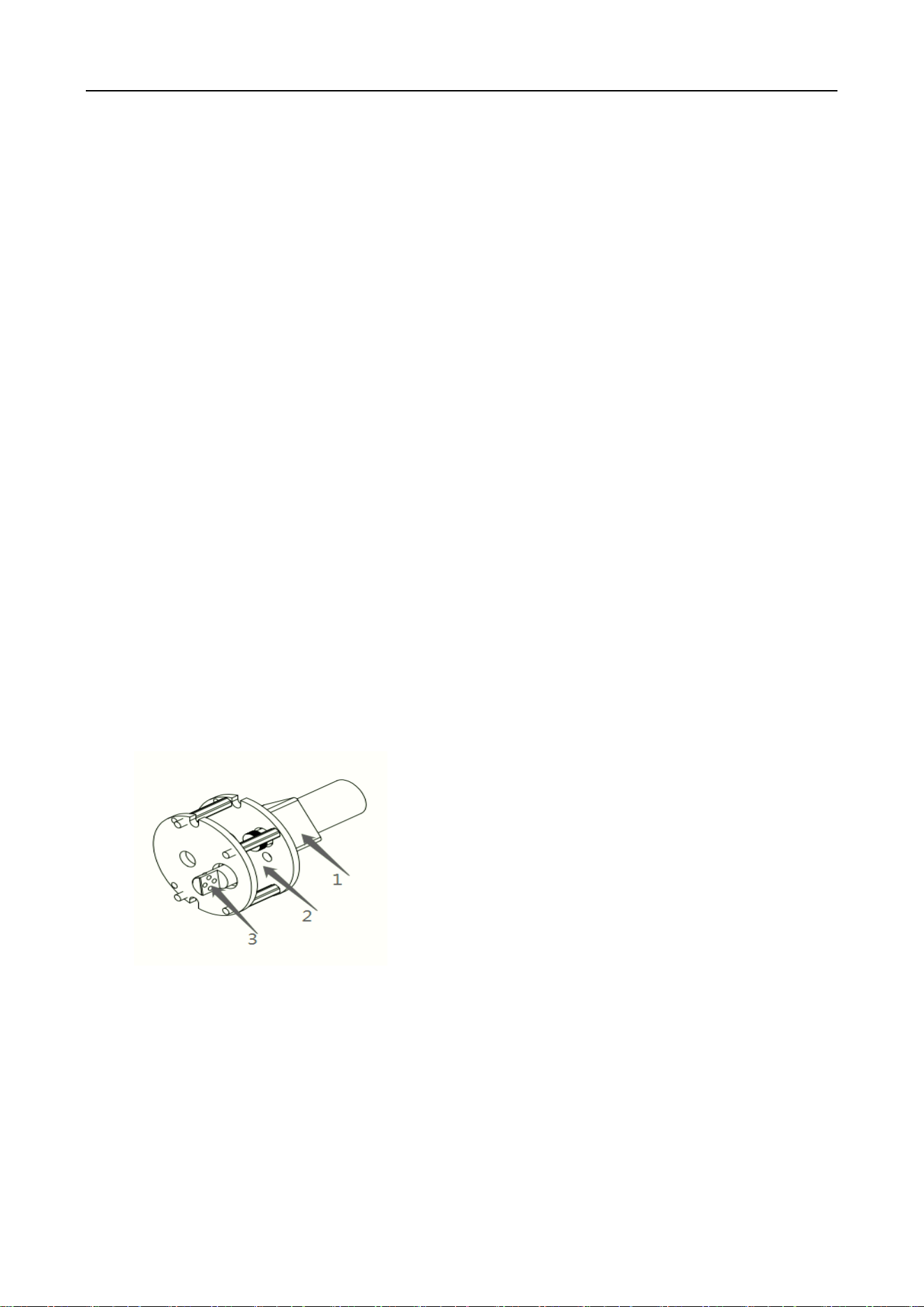
The core mechanism is composed of motor, position sensor, transmission, shaft.
Swing core
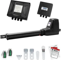
The electric control system consists of access control system, control board, infrared sensor,
direction indicator, position sensor, motor, power supply, battery and so on.
1. Motor
2. Core
3. Roting shaft

Swing Barrier • User Manual
7
NO
Name
Function
1
Access control
device
IC/ID card access control, fingerprint, face recognition, code
reader, access control device send delay signal to the
turnstile board door signal. Remote control or button to
open the door(select the configuration)
2
Main board
(control)
The control center of the system, when receiving the access
control device delay signal, it control motor running so that
the gate opened, the direction indicator light turns green,
while receiving core position sensor, infrared sensor, and
judging and processing logic of these signals, keep the gate
components of intelligent coordination work
3
Infrared sensor
Detect the passage of people in the lane, Anti pinch
4
Indicator
Display the current channel status
5
Position sensor
Detects and controls the opening and closing position of the
gate
6
Motor
Drive the barrier moving
7
Power Supply
power supply to control board
8
12V battery
The gate will keep open the door automatically when
power failure
System Operation Principle
1) Turn on the power, wait for the end of the self-examination ; the system enters into work
mode;
2) After swipe legal card or QR code and fingerprint, Access control device send opening
signal to main board.
3) The main board receives open signal, control indicator to green, motor acts to open the
barrier.
4) After the passenger passing through the passage in accordance with the direction indicator

Swing Barrier • User Manual
8
mark, the infrared sensor detects the complete process of the passenger passing through the
passage, and issues signal continuously to the main controller board, until the passenger passes
through the passage completely.
5) After the passenger passes through the passage completely, the main controller board
delivers a signal to the counter, which will increase 1 automatically, ending the passing process.
6) If the passenger forgets to swipe card when go into the passage, sound/light alarm signal
will be given from main board. The alarm signal will not be cancelled until the passenger retreats
from the passage and the passing is only allowed after reading again the effective card
1.3 Function Features
Varied pass mode can be chosen flexibly;
Standard signal input port, can be connected with most of the access control board,
fingerprint device and scanner other equipment;
The turnstile has automatic reset function, if people swipe the authorized card, but don’t
pass through within the settled time, it need to swipe card again for entry;
Card-reading Recording function: single-directional or bi-directional access can be set by the
users
Automatic opening after emergency fire signal input
Pinch protection;
Anti-tailgating control technology
Automatic detection, diagnosis and alarm, sound and light alarm, including trespassing
alarm, anti-pinch alarm and anti-tailgating alarm.
High light LED indicator , displaying passing status.
Self diagnostic and alarm function for convenient maintenance and use
Gate will automatically open when power failure(connect 12V battery)
1.4 Technical parameter

Swing Barrier • User Manual
9
Housing Material
304 stainless steel
Power
AC220±10% V、50HZ
Working voltage
DC 24V
Motor
Brush DC motor 30W
Working temperature
-20 ℃ - 60 ℃
Work environment
≦90%, no condensation
Open signal
Passive signals (relay signals, dry contact signals,)
Communication
RS485
Pass rate
≦35 person/min
Passage width
Swing gate 600--900mm
2 Equipment Installations
2.1 Installation notes
Please read this manual carefully before install it;
The gates must be correctly arranged in order, and the left and right gates of each lane should
be aligned;
If the equipment is used outdoors, equipment should be installed at the establishment of
100-200mm high cement platform, so as to prevent moisture, and install ceilings and other
sunscreen, rain protection facilities;
Protective earth wire must be connected;
Please confirm each RJ45 cable straight through;
Please check all wires has been properly connected before power on;
Please test all function before using.
2.2 Equipment Installation
1) Tool preparations
Swing Barrier • User Manual
10
1
A set of hexagon spanner
5
Screw driver and other common wiring
tool
2
Cross screwdriver 6mm
6
Millimeter
3
Open spanner 17-19mm
7
M12x100 Expansion screws 8pcs
4
Impact drill(including D16 and
D14 drills)
8
Cable Tester
2) Ensure the installation location and the system composition ,prepare to install after
carrying out the system planning;
3) Make well of installation of equipment foundation base.
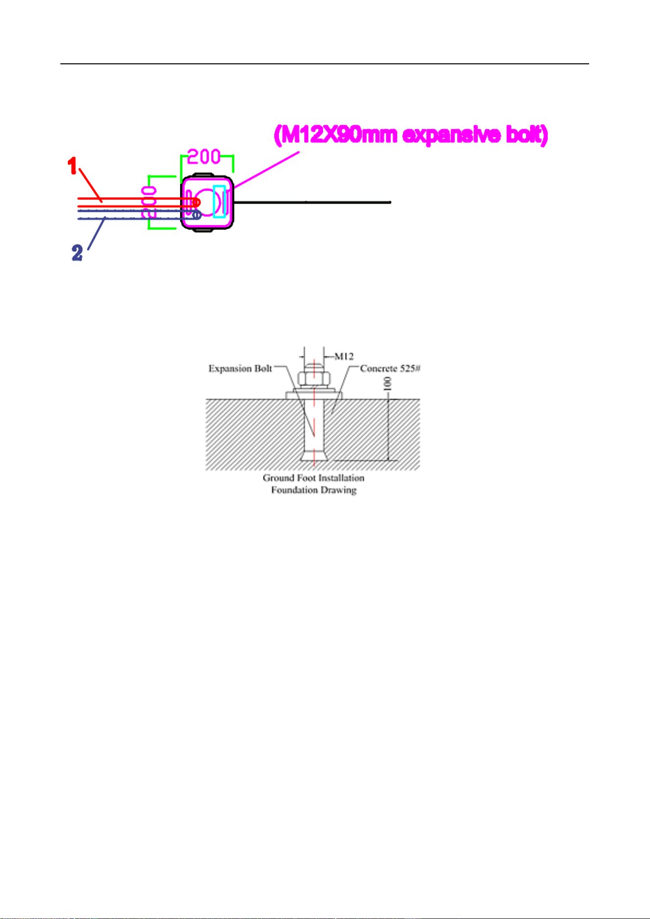
4) Mark the fixing position of expansion bolts according to fixing plate on the bottom of
each turnstile.
Swing Barrier • User Manual
11
5) Move turnstile and drill hole by impact drill, fix Expansion screws
6) Tighten the expansion screw after the functional test is completed
\
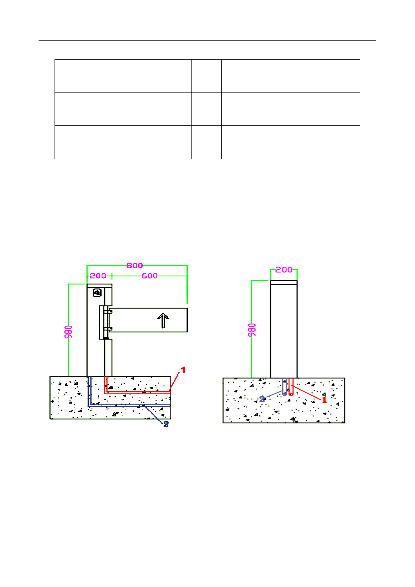
7)Confirm the lane lines, dig line pipe diameter into the appropriate PVC line pipe, each lane
will AC220V power line RVV3*1.5mm and 3pcs CAT 5 cable for connect main machine , 1 PCS
network cable for access control system (if install other control system according to the actual
situation of laying related field the wire)
8) Move each machine to the corresponding mounting position and point to the expansion
bolt position;
9) Check again;
10)Check each gate alignment, all lane are completed debugging and function test, then tighten
the nut.
2.3 Connection
1) Connecting AC220V power input
Connect the mater machie power adapter to 220V and connect the protective ground wire.
Swing Barrier • User Manual
12
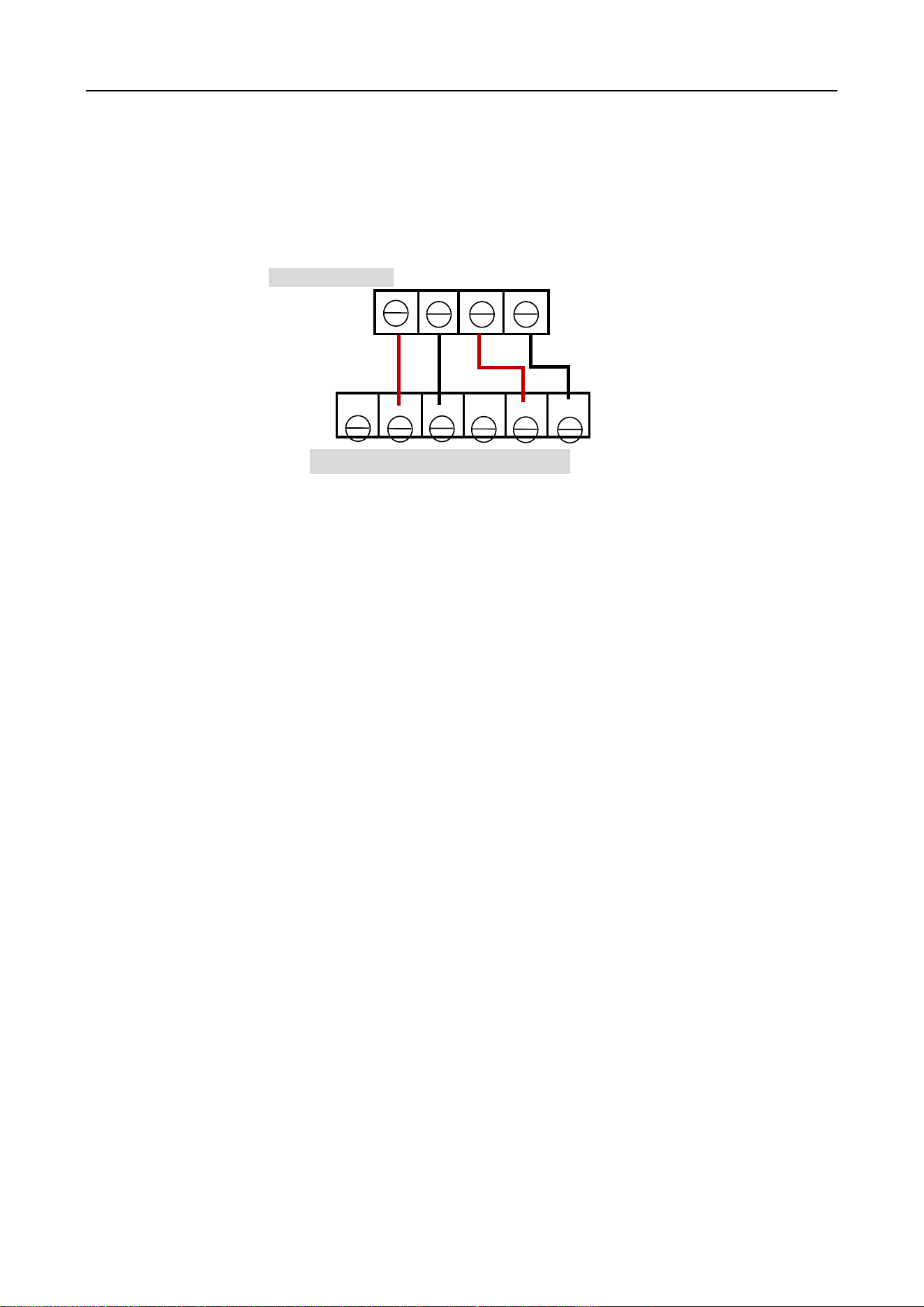
2)Access control device connect
Access control device send open signal to control board , gate will open immediately ,The relay
time of access control device must be set to 0-1 seconds.
Enter SW Exit SW
SW1 Gnd SW2 Gnd
2.4 Debugging instruction
1)Check wire:Check whether the connection wire of the gate and the power line are properly
connected before power on. If there is any abnormality on the power supply process, check the
connection wires firstly;
2)Function test:After power on the machine will open- close, and open -close, this process is
machine self-check, after the sound from buzzer means finish self-check. Don’t stand in the lane in
the process of self-check;
3)The control board will give alarm if stand in the lane without swipe card ;if no response when
infrared sensor be block, please check if the infrared sensors are aligned,Under normal
circumstances, the red led of receive sensor is no bright when no blocked .If the red led of
receive sensor is always bright ,that means the sensors no shoot well ,please adjust to aligned.
4)The relay time of access control device must be set to 0-1 seconds.
5)When the valid card is swiped, the indicator light turn green,If the indicator indicates
incorrect or turn off and alarm immediately when go into first sensor, This means that the signal
connection is opposite, exchange the open signal connect terminal of SW1 Gnd to SW2 Gnd
6)Check and test carefully, running smoothly, no abnormal condition, no impact sound, etc;
Confirm motor is no idle; the indicator light is correct and the infrared pinch function is normal
before putting into use.
Main board
Access control device
NC NO COM NC NO COM
mark:
SW1---NO
Gnd-----COM
SW2----NO
Gnd-----COM

Swing Barrier • User Manual
13
2.5 Notice of use
If it tests well before installation, then fixed it; before you install and maintain it, please cut off
the power;
The product must be earthed, and an earth leakage breaker is necessary on the power supply;
The depth of buried PVC tube should be greater than 60mm, and the exposed height above the
ground should be greater than 50mm. The exit mouth should be bending back to avoid water
dipping inside the tube;
Don’t change the inside wire of the turnstile casually;
Please don’t open the turnstile when it is under the working status;
In installation, please make each door of the lane are in alignment;
If you use the turnstile outdoor, it need to add a 100-200mm cement platform for the turnstile
to do damp proof, also need to add a canopy to protect the turnstile from sun and rain;
Please keep the control button or remote control far away from the children;
Please don’t use the turnstile under the thunder and lightning condition to get rid of damage to
the equipment.
Swing Barrier • User Manual
14
3 Board and parameter instruction
3.1 Board instruction
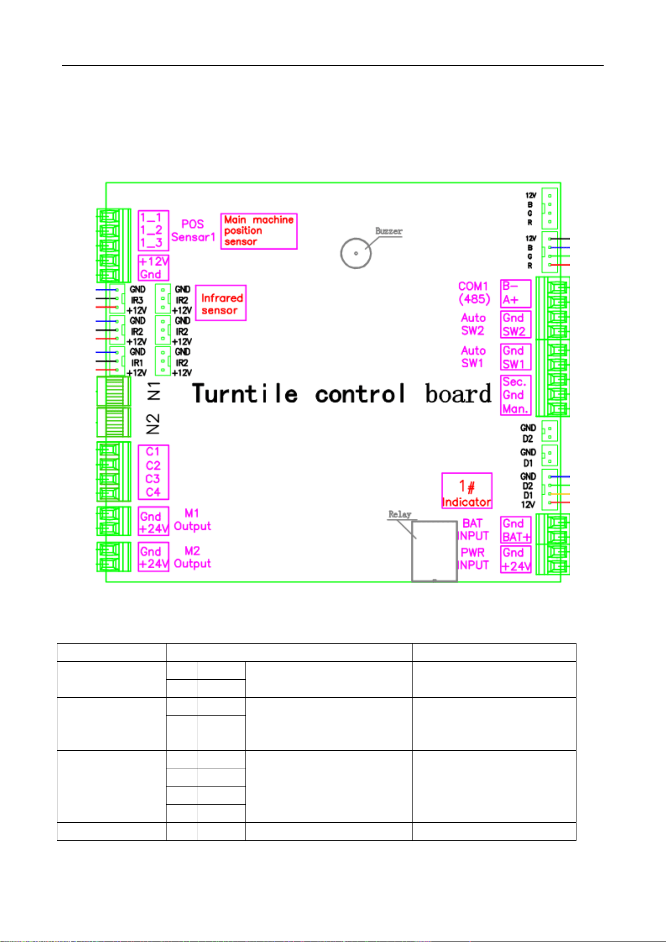
Main board
The connect board
Port
Instruction
mark
(1) PWR INPUT
1
+24V
24VDC power supply
Connect to 24V DC power
supply
2
GND
(2) BAT INPUT
3
BAT+
12V battery input port
Connect the 12V battery,
Auto normally open when
power off.
4
GND
(3) Entry
Indicator1
5
+12V
Output for indicator of
master machine
D1 for enter direction
D2 for exit direction
Connect to indicator of
master machine
6
GND
7
D1
8
D2
(4) Man
9
Man
Normally open input
Short for normally open ,

Swing Barrier • User Manual
15
Gnd
Sec
10
Gnd
Fire alarm input
Close immediately when
cancel
11
Sec
(5) Auto SW1
12
SW1
Enter open signal input
Connect to access device
NO-SW1 COM-Gnd
13
Gnd
(6) Auto SW2
14
SW2
Exit open signal input
Connect to access device
NO-SW1 COM-Gnd
15
Gnd
(7) COM1(485)
16
A+
RS485 communication
Protocol docking
17
B-
(8) RGB LED
18
R
Negative of LED red
Negative of LED green
Negative of LED blue
+12V for LED bar
Connect to LED bar
19
G
20
B
21
+12V
(9) POS Sensor1
22
1-1
left sensor
Close sensor
Right sensor
Connect to position sensor
of core in the master
machine,flap /slide gate
only use two sensor(open
and close)
23
1-2
24
1-3
25
+12V
12V output for sensor
26
GND
(10) IR Sensor
27
IR1
Enter infrared sensor
Pinch infrared sensor
Exit infrared sensor
Control board alarm when
sensor be block
28
IR2
29
IR3
30
+12V
12V output for infrared
31
GND
(11) N1 Entry
Indicator 2
POS Sensor2
32
D2
Output for indicator of
master machine
D1 for enter direction
D2 for exit direction
Connect to indicator of
master machine
33
D1
34
GND
35
+12V
36
2-1
left sensor
Close sensor
Right sensor
Connect to position sensor
of core in the master
machine,flap /slide gate
only use two sensor(open
and close)
37
2-2
38
2-3
39
+12V
12V output for sensor
40
GND
(12) N2
41
C1
Reader reserve a place
42
C2
43
C3
44
C4
45
R
Negative of LED red
Negative of LED green
Negative of LED blue
+12V for LED bar
Connect to LED bar
46
G
47
B
48
+12V
(13) M1 output
49
GND
Motor output for mater
machie
Connect to motor of
master machine
50
+24V
Swing Barrier • User Manual
16
(14) M2 output
51
GND
Motor output for vice
machie
Connect to motor of vice
machine
52
+24V
3.3 Parameter instruction
Description: the factory has been set up parameters, please do not modify, if you need to
modify the parameters, please proceed under technical guidance.
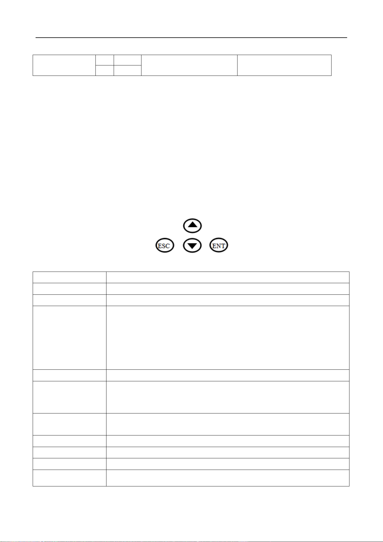
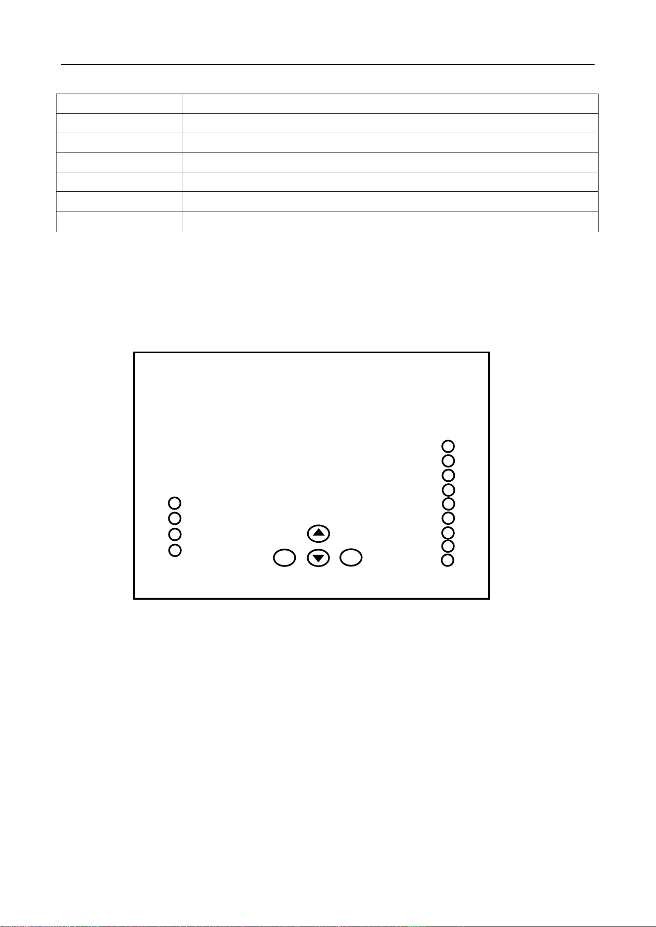
1. Description
1) The display screen is refers to the main control board of 3 LED display from left to right. Four
buttons: up and down for switch, ENT for sub-menu, ESC for previous menu. Long press "ENT " 3
seconds unlock into the menu.Select advanced parameters, and long press "ENT + Down " 3 seconds
unlock into the menu.
2.Menu setting
Item
Explain
1. Parameters
1.1 Counter
Display pass through count
1.2 Gate Mode
Set Gate Mode(NO, NC and card, free or reject) of enter and exit
1.NC both Rej 2 .NC both free 3.NC both card (default)
4 NC Card Free 5 .NC Card Rej 6. NC Free card
7.NC Free Rej 8.NC Rej Free 9.NC Rej Card
10.NO Both Free 11.NO Both Card
12.NO Card Free 13.NO Free Card
1.3 PassTimeout
Set maximum waiting time 10-255, unit 0.1s, (default 5seconds)
1.4 Memory
Set Scan Card With Memory Mode
0 two-way disable(default),1. enter allow,2. exit allow,3. two-way allow
1.5 ReadIn Lane
Set Can Scan Card After Entry Lane,Please do not modify
1. disable (default), 2. allow
1.6 Open Delay
Set Authorized Open Door Delay 0-255, unit 0.1s, (default 0)
1.7 CLS. Delay
Set Close Door Delay After Passage Finish0-255, unit0.1s, (default 0)
1.8 Motor1 SPD.
Set master Motor basic speed 1-100
1.9 Motor2 SPD.
Set vice motor basic speed 1-100

Swing Barrier • User Manual
17
1.10 Pass End
Set IR Check passage end position 1. exit (default), 1 safety
1.11 Intrude Set
Set Intrude Alarm Mode 1.no alarm, 2 .alarm (default), 3. alarm and close
1.12 Reverse Set.
Set Passage From Reverse Alarm Mode
1 no alarm, 2. alarm, 3 alarm and close (default),
1.13 Tail-Gating
Set Tail-Gating Alarm Mode 1 no alarm, 2. alarm, 3 alarm and close
(default),
1.14 Adv. Param.
.1 EN_O_SPD.1
Set Motor 1 Speed when Open Door for Entry
.2 EN_C_SPD.1
Set Motor 2 Speed when Open Door for Entry
.3 EX_O_SPD.1
Set Motor 1 Speed when Close Door for Entry
.4 EX_C_SPD.1
Set Motor 2 Speed when Close Door for Entry
.5 EN_O_SPD.2
Set Motor 1 Speed when Open Door for Exit
.6 EN_C_SPD.2
Set Motor 2 Speed when Open Door for Exit
.7 EX_O_SPD.2
Set Motor 1 Speed when Close Door for Exit
.8 EX_C_SPD.2
Set Motor 2 Speed when Close Door for Exit
.9 Save Fact.
Save the current parameter to factory default
.10 Relay Mode
Set add relay use for passed counter
1. disable,(default),2.Enter allow, 3.Exit allow ,4. both ballow
.11 Auto Report
Set automatic report gate status when on change 1 disable (default), 2
allow
.12 NO Direction
Set the normally open the gate opening direction , the default enter
.13 Power Lost
Set the normally open the gate opening direction when Power failure , the
default enter
.14 Barriers
signal or double machine work 1 double (default) , 2 signal
.15 IR Speed
Set IR Sensor Sensitivity(1-100) 0-100(default 100)
.15 IR Type
Set infrared sensor type 1 PNP (default), 2 NPN
.16 IR Logic
Set Use Local IR Sensor Logic
.17 Motor Pro.
Set the motor over current protection threshold, the default 2.5A
.18 Self Check
Set use self check when power on, disabled by default
.19 LED Mode
Set LED indicator default parameter 1 Static LED,2 Square LED
.20 Set DevType
Set Controller Device Type 1 Tripod 2 Flap gate, 3 Swing gate
2. System Set
2.1 Language
Set Menu Display Language
2.2 Device Type
Display Controller Device Type
2.3 Version
Display hardware and firmware version information
2.4 Set Address
Set Device Logic Address
Swing Barrier • User Manual
18
2.5 RS485 Baud
Set the baud rate of the RS485
2.6 Reset
Reset all setting to factory default.
2.7 Restart
Restart controller
3. Factory Test
3.1 Cycle Test
Open and close door cycle test
3.2 Input Check
Check input interface status
3.3 Output Test
Output interface test
4 Trouble shooting and maintenance
4.1 Trouble shooting
The box of control is buckle type ,It can open the upper cover of the buckle from the side.
Fault 1: Gate automatically open when people in to first sensor?
Answer:Change pass mode two way free to two way card in the menu.
Fault 2: swipe into the first sensor, Gate give alarm and close immediately?
Answer:This means that the signal connection is opposite, exchange the open signal connect
terminal of SW1 Gnd to SW2 Gnd.
Fault 3: indicator light is not bright?
Answer:Take the other indicator or control board from other lane and check it
Fault 4: is there an indicator that shows the wrong direction?
1 2 3 4 5 6 7 8 9
ESC ENT
Control board

Swing Barrier • User Manual
19
Answer:Exchange the connect wire of indicator D1 to D2.
Fault 5: Motor idling?
Answer:1)Check whether the POS Sensor connect wires are loose;2)Turn off the power and use
the millimeter to check whether the connection between the master machine and the vice
machine is continuous.3)Check the vice board 12VGND for voltage output
Fault 6: there is one side of barrier is not closed?
Answer:1)Check whether the POS Sensor connect wires are loose;2)Turn off the power and use
the millimeter to check whether the connection between the master machine and the vice
machine is continuous.3)Check the vice board 12VGND for voltage output
Fault 7: swing the side of the pendulum rod can only open 90 degrees, or open the side of the
pendulum rod hit the box?
Answer:1) check the abnormal barrier and the normal one whether there is any difference
between the fixed angles and whether the pendulum rod is struck or not 2)Check the iron sheet of
core whether is loose, if loose readjust it.
Fault 8: The swing gate move slowly or shake or give big noisy?
Answer:Check core
4.2 Maintenance
Swing /falp barrier gates require regular maintenance by professionals and daily cleaning to
ensure long-term stability and extended equipment life.
1. Maintenance Content:
* Keep the turnstile housing and card reader panels of turnstile gates clean;
* Fasten and lubricate the internal movement structure;
* Check the dust of the driver board and make it cleans.
* Check the connectors and wiring points to ensure the reliability of the connection.
2 Maintenance Methods:
1. Cleaning: Check the housing and card reader panels of the gate, and remove the dust and other
dirt to make them clean;

Swing Barrier • User Manual
20
2. Rust removal and Lubrication: Check the movement of the flap /slide gate and swing gate, remove
rust with sand paper and spread with anti-rust oil if corroded;
3. Screws fastening: Check the connection of the various moving parts, fasten the screws where they
are loose to avoid causing fault for long-running;
4. Circuit board cleaning: Cut off the power, and wipe dust of the board by using a clean brush;
5. Lines Checking: Check the connecting lines and solder reinforcement if they are loose off.
Note: This product is the strong professional technical equipment. In addition to daily maintenance,
please do not feel free to disassemble it. If a fault occurs while running, Please notify our service
departments or the authorized service agencies promptly to have it maintained. Do not disassemble
it at random to avoid damaging the internal structure or even damaging your interests because of
your improper operation.